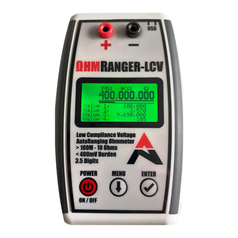
ALTONOVUS OR-01 User manual

1
OR-01 Instruction Manual V1.0 dated 14 Mar 22 –OR Software V2.20 and above
Instruction Manual
OR-01 Low Compliance Voltage Ohmmeter

2
OR-01 Instruction Manual V1.0 dated 14 Mar 22 –OR Software V2.20 and above
Disclaimer
ΩhmRanger-LCV™ is a factory-calibrated, accurate low compliance voltage ohmmeter, intended
for measuring resistance without subjecting the Device Under Test (DUT) to excess stimulus
voltage. It is aimed at both the professional and the enthusiast User. ΩhmRanger-LCV™ is not
intended to replicate the full functionality of expensive laboratory equipment. Instead, it aims to
provide a portable and affordable means of measuring the resistance of delicate components,
where this has in the past required engineers to develop their own rigs.
If used in any manner other than that expressly set out in the AltoNovus product documentation,
warranties granted by AltoNovus shall be deemed void and AltoNovus shall not be liable for any
claims, or damages arising out of product misuse or malfunction.
Although every effort is made to ensure the accuracy of ΩhmRanger-LCV™, no guarantee of
accuracy is given or implied, or responsibility accepted for consequential loss. Users may
reproduce and store this document for personal use. For wider permission requests, email the
publisher, addressed “Attention: Permissions Coordinator,” at i[email protected]. The name
ΩhmRanger-LCV™ is Trademark 2022 AltoNovus Limited. The name ΩhmRanger-LCV™ will
be a Registered Trademark of AltoNovus Limited.
Document Revisions
DATE
VERSION NUMBER
DOCUMENT CHANGES
14 Mar 22
1.0 (Software Release 2.20)
Launch Release
Approvals - Release / amendment of this document requires the following approvals:
NAME
ROLE TITLE
Geoff Dean
Managing Director
Steve Thickett
Technical Director

3
OR-01 Instruction Manual V1.0 dated 14 Mar 22 –OR Software V2.20 and above
TABLE OF CONTENTS
1Preface................................................................................................................................5
1.1 The User..............................................................................................................................5
1.2 Conventions Used in This Manual.......................................................................................5
1.3 Explanation of Safety Warnings...........................................................................................5
1.4 Obtaining Documentation and Information..........................................................................5
2ΩhmRanger-LCV™ ............................................................................................................6
2.1 Utility and Employment........................................................................................................6
2.2 Theory of Operation.............................................................................................................6
2.3 Technical Data.....................................................................................................................8
2.4 Compliance..........................................................................................................................9
2.5 Guide to Product..................................................................................................................9
2.6 Understanding the User Interface........................................................................................9
2.7 Device Set-Up....................................................................................................................10
2.8 ΩhmRanger-LCV™ Menu Structure..................................................................................12
3Safety................................................................................................................................15
3.1 Using ΩhmRanger-LCV™ Safely ......................................................................................15
3.2 Guide to Graphical Symbols..............................................................................................16
4Taking Manual Readings ................................................................................................18
4.1 Switch ΩhmRanger-LCV™ ON .........................................................................................18
4.2 Automatic Range-Switching...............................................................................................18
4.3 The Signal to Noise Ratio (SNR).......................................................................................18
4.4 Switching ΩhmRanger-LCV™ OFF...................................................................................19
5Getting Connected - taking PC-Controlled Readings & SCPI Commands................20
5.1 SCPI Mandated Commands:.............................................................................................20
5.2 SCPI Required Commands: ..............................................................................................21
5.3 Device Commands (Routine Use).....................................................................................21
5.4 Device Commands for Advanced Use only (not normally required)..................................23
6Storage, Transportation and Disposal ..........................................................................25
6.1 Storage ..............................................................................................................................25
6.2 Packaging and Transportation...........................................................................................25
6.3 Disposal.............................................................................................................................25

4
OR-01 Instruction Manual V1.0 dated 14 Mar 22 –OR Software V2.20 and above
7Maintenance.....................................................................................................................26
7.1 Replacing the Batteries......................................................................................................26
7.2 Cleaning.............................................................................................................................26
7.3 Recalibration......................................................................................................................26

5
OR-01 Instruction Manual V1.0 dated 14 Mar 22 –OR Software V2.20 and above
1 Preface
1.1 The User
ΩhmRanger-LCV™ is not a toy. It is a precision instrument and should be treated accordingly.
It is aimed at the professional and enthusiast User community. This Instruction Manual
assumes a level of technical expertise on the User’s part. ΩhmRanger-LCV™ should not be
used by those without a knowledge of safe working on electronics. This Manual covers the use
and operation of ΩhmRanger-LCV™. It does NOT cover calibration or maintenance (beyond
battery replacement or routine cleaning), as these are not activities that the User can perform.
1.2 Conventions Used in This Manual
The following style conventions are used in this document:
Courier New
SCPI System control inputs and outputs.
User input variables
< > Angle brackets surround User-supplied values.
1.3 Explanation of Safety Warnings
CAUTION! Indicates a hazard with a low level of risk which, if not avoided, could result in damage
to ΩhmRanger-LCV™ and / or minor injury to Users.
1.4 Obtaining Documentation and Information
1.4.1 Internet
The latest version of the documentation and any software updates are available at the following
web address: http://www.altonovus.com.
1.4.2 Ordering Documentation
Documentation, User instructions and technical information can be requested by emailing:
1.4.3 Documentation Feedback
We welcome your comments and ideas, which may be incorporated in a ΩhmRanger-LCV™
FAQs page. Any comments, requests for clarification, or suggestions for future Versions of this

6
OR-01 Instruction Manual V1.0 dated 14 Mar 22 –OR Software V2.20 and above
2 ΩhmRanger-LCV™
2.1 Utility and Employment
ΩhmRanger-LCV™ is an accurate, affordable, low compliance voltage ohmmeter, for the
measurement of resistance of components that cannot be exposed to large stimulus voltages.
One example is the delicate Josephson Junction that forms the ‘transistor equivalent’ of some
quantum computers. Previously, engineers have been required to develop their own
measurement rigs to test such components.
The ΩhmRanger-LCV™ is a solution to this challenge, as it provides accurate measurement
from >100M to 10 Ohms, with a stimulus voltage always less than 400mV. It features:
•Low stimulus voltages, selectable between approximately 380mV or approximately 206mV, with
on-screen voltage confirmation.
•Stimulus voltage at the output terminal is limited by the maximum current supply of approximately
30mA.
•Readings from >100M to 10 Ohms.
•A 128 x 64 LCD display gives a wealth of information about your Resistance readings.
•A large display shows MΩ, KΩ, and Ω, all on one line.
•Readings every 400mS, built up from 160 samples and averaged to tune out mains noise (both
50 Hz and 60 Hz).
•Fully isolated USB Interface for device control and readings export.
•SNR display to indicate noise level on signal.
•Range Bar movement after every reading to show that ΩhmRanger-LCV™ is operating correctly.
•Range Coverage Bar that shows the ranges covered during the measurement.
•User-configurable Auto Power-off timer.
•A small form, with dimensions of 148 x 90 x 30mm, making ΩhmRanger-LCV™ highly portable.
•150 hours of operation on 2 x AA batteries.
•An automatic Power Off timer, and configurable LED backlight, enabling the User to maximise
battery life.
Readings are completed approximately every 400mS and the display is updated, with samples
collected and averaged out to remove most of the mains noise associated with circuits (50Hz and
60Hz).
2.2 Theory of Operation
ΩhmRanger-LCV™ is powered by 2 x AA batteries (not supplied), generating approximately 3V (but
will continue to work down to approximately 2V on the batteries).
Pressing the Power On button starts the ΩhmRanger-LCV™. Pressing the Power On button again
powers off the ΩhmRanger-LCV™. Standby current, when powered off, is approximately 10nA.

7
OR-01 Instruction Manual V1.0 dated 14 Mar 22 –OR Software V2.20 and above
The ΩhmRanger-LCV™ is developed from AltoNovus’ NanoRanger, which is an auto-ranging
ammeter used to measure low currents, with great accuracy, through decadal ranges.
ΩhmRanger-LCV™ has an additional, readable voltage source.
The stimulus voltage selected is output on the Positive terminal of the ΩhmRanger-LCV™ and
the resistance to be measured is connected across the terminals. The two voltage outputs that
can be selected by the User are approximately 380mV and 206mV. The actual voltage output is
displayed on the device screen.
ΩhmRanger-LCV™ measures the current coming in through the Negative terminal by measuring
the voltage across an internal range resistance. The ΩhmRanger-LCV™ can measure currents
down to 1nA by switching in different range resistances. The device has 9 internal range
resistances used to measure current, with a 40mV full scale burden voltage. The maximum
current we can measure (together with the associated range resistance) per range is:
Range Number
Internal Range Resistance
Max current @40mV
0
2MΩ
20.00nA
1
200KΩ
200.0nA
2
20KΩ
2.000uA
3
2KΩ
20.00uA
4
200Ω
200.0uA
5
20Ω
2.000mA
6
2Ω
20.00mA
7
0.2Ω
200.0mA
8
0.05Ω
800mA
The resistance is computed by dividing the output voltage by the measured current (R=V/I)
before subtracting the range resistance. Factory set calibration compensation is applied to
both current and voltage, to give an accurate reading of resistance. i.e. R_TOTAL = R +
R_INTERNAL = V/I. In the example shown on the screen below:

8
OR-01 Instruction Manual V1.0 dated 14 Mar 22 –OR Software V2.20 and above
R + R_INTERNAL = 0.2067V / 89.8nA (here using Range 1, where the associated Range
Resistance is 200KΩ). Therefore:
R + 200KΩ= 2.3MΩ, and
R = 2.3MΩ–200KΩ= 2.1MΩ
For clarity, the User can see the 3 values above V (206.7mV), I (89.8nA), and the Range (1) on
the display in real time, and live, during measurement, as shown above.
Please Note: Although range 8 exists in the OhmRanger, because the current is limited to
approx. 30mA we will never switch up to that range from the 200.0mA range.
2.3 Technical Data
UNIT
PHYSICAL PARAMETERS
Weight (not including batteries)
Approximately 200g
Length x Width x Depth
148 x 90 x 30 mm
Accuracy specifications +/- % of range:
RESISTANCE
ACCURACY
>100MΩ
5%
1-100MΩ
2%
100-1MΩ
1%
<100Ω
2%
•Current consumption LCD Light on < 15mA.
•Current consumption LCD Light off < 10mA.
•Current consumption Powered-off < 10nA.
•Typical operating time on one set of 2 x AA batteries is > 150 hours.

9
OR-01 Instruction Manual V1.0 dated 14 Mar 22 –OR Software V2.20 and above
UNIT
OPERATIONAL PARAMETERS
Temperature
0 –50C
Humidity
10 –90% non-Condensing
2.4 Compliance
ΩhmRanger-LCV™ is certified UKCA, CE and FCC compliant. A supporting Technical File is
available to Competent Authorities on request.
2.5 Guide to Product
A - Positive Terminal
B - Negative Terminal
C - Display Screen
D - On / Off Button
E - Menu Navigation
F - Select Button
G - Isolated USB Interface
H - Battery Compartment
2.6 Understanding the User Interface
A - The Resistance reading, displayed in MΩ, KΩ and Ω. In the example above, 2.1MΩ.
B - A small, oscillating Range Bar shows which range is currently in use. An upper, longer Range
Coverage Bar shows any movement across the ranges during the reading (in this example,
none). The box surrounding shows the operating range.

10
OR-01 Instruction Manual V1.0 dated 14 Mar 22 –OR Software V2.20 and above
C - The Voltage being applied by ΩhmRanger-LCV at the Positive terminal, in this case
206.7mV, to measure the resistance.
D - The active Range and the observed Current.
E - The Signal to Noise Ratio (SNR). The SNR indicates how much noise, variation, and AC
components are in the signal, followed by Maximum and Minimum Current samples during the
reading. Higher resistances (lower currents) are more susceptible to noise. In this example
currents ranged from 102.2nA down to 77.1nA. At these current levels mains pickup in the test
leads are the biggest source of noise.
2.7 Device Set-Up
2.7.1 Fitting 2 x AA Batteries
1. Remove battery compartment cover, by applying gentle pressure
to the finger pad.
2. Ensure clean contacts on batteries.
3. Insert new batteries, observing polarity instructions in battery
compartment:
4. Replace battery compartment cover.
Note: 2 x AA alkaline batteries should give more than 150 hours of continuous operation. Treat
and dispose of all batteries in accordance with manufacturer’s instructions.
2.7.2 Removing the Protective Film
If desired, remove the protective film from the front of ΩhmRanger-LCV™. Peel carefully
from below the Positive and Negative terminals. ΩhmRanger-LCV™ will still function
normally if the User chooses to leave the film in place.
2.7.3 Attach Feet (if desired)
ΩhmRanger-LCV™ is supplied with 4 rubber feet, for Users requiring added stability. Attach
these with due regard to the areas that will experience pressure during normal use; i.e. the
Keypad buttons and Terminals. Attaching the Feet as shown below will improve the stability of
ΩhmRanger-LCV™ during use.

11
OR-01 Instruction Manual V1.0 dated 14 Mar 22 –OR Software V2.20 and above
2.7.4 Connecting User Probes
Using User Probes (not supplied), Connect the Resistance to be measured between the Positive
(RED) and Negative (BLACK) terminals of the ΩhmRanger-LCV™. Leads should be industry
standard, uninsulated, 4mm banana plug type. As short a lead as practicable (0.3M) will help
minimise noise during measurement.
2.7.5 Controls
Firstly, ensure batteries are fitted in accordance with 2.7.1 (above). Three buttons control the
operation of the ΩhmRanger-LCV™; Power, Menu, and Select. Pressing the Power button will
start the ΩhmRanger-LCV™. Two start-up screens will display, whilst loading the code. The first
screen shows the AltoNovus logo:
Then a second screen, shown below, will appear briefly, with the serial number of the
ΩhmRanger-LCV™ (here 2205102), the software release (here ALT-2.20), calibration date and
calibration load status. Taking measurements can then commence (See Section 4).

12
OR-01 Instruction Manual V1.0 dated 14 Mar 22 –OR Software V2.20 and above
2.8 ΩhmRanger-LCV™ Menu Structure
ΩhmRanger-LCV™ has several features accessible through the Menu. Press the Menu button
to exit measuring and enter the Menu. The screen below will appear:
Selecting Measure will take the User back to measuring mode. Pressing the Menu button will
scroll through the menu options. The Menu options are currently:
•Measure
•Voltage
•Powerdown
•LCD Light
•4 Beep Read
•Details
These Menu options may change in the future. ΩhmRanger-LCV™ software updates are
2.8.1 Measure
The Measure feature performs a measurement, as described in Section 4.
2.8.2 Voltage

13
OR-01 Instruction Manual V1.0 dated 14 Mar 22 –OR Software V2.20 and above
This feature allows the User to specify the stimulus voltage that will be applied by ΩhmRanger-
LCV™ to the Device Under Test (DUT). There are 2 options, approximately 380mV (the default
setting), or 206 mV.
Configuration is saved to Non-Volatile memory and restored on Power Up.
2.8.3 Powerdown
This feature enables the automatic Power Off timer. The timer starts at the most recent
interaction with ΩhmRanger-LCV™ (the last key press). The timer options are: Off, 30mins, 1hr
(Default), 2hrs, 4hrs, and 8hrs.
Configuration is saved to Non-Volatile memory and restored on Power Up.
2.8.4 LCD Light
This feature enables / disables the LCD backlight. Disabling the backlight will extend battery life.
Configuration is saved to Non-Volatile memory and restored on Power Up.
2.8.5 4 Beep Read
The 4 Beep Read function is intended to enable Users to ignore fluctuating resistance
measurements and to save readings only when a stable resistance value is detected.

14
OR-01 Instruction Manual V1.0 dated 14 Mar 22 –OR Software V2.20 and above
This mode of operation also gives an audio cue to notify Users who may need to keep the Device
Under Test (DUT) under close observation during the measurement process.
To begin the process, ΩhmRanger-LCV™ takes a measurement and stores the value (as the first
in the sequence). With the second and subsequent measurements, ΩhmRanger-LCV™ checks
the new value against the value stored for the first. If the new value is within the selected stability
tolerance (either 1%, 2%, 5%, or 10%) then ΩhmRanger-LCV™ increases the count.
If the new value is not within the set tolerance, then this measurement replaces the previous value and is
stored as the new ‘first’ in the sequence (and the count is reset). If the count reaches 5 (i.e. 5 sequential
values are within tolerance) then the reading is stored and a beep sounds. If nothing is connected
(400MΩ), any values captured are not counted as readings and the count restarts. This process repeats
until all 4 slots for stored readings are filled. The slots for stored readings can be cleared by pressing the
ENTER button.
Configuration is saved to Non-Volatile memory and restored on Power Up.
2.8.6 Details
Under this Menu option, the User can find information about the ΩhmRanger-LCV™’s Software
version, Serial number, Calibration date and Calibration status, as shown below:
2.8.7 Exiting the Menu and Clearing Readings
Select Measure to exit the Menu and return to the Measure screen. While on the Measure
screen, pressing the Select key will clear the Reading from ΩhmRanger-LCV™.

15
OR-01 Instruction Manual V1.0 dated 14 Mar 22 –OR Software V2.20 and above
3 Safety
CAUTION! Please use ΩhmRanger-LCV™ only as described in this Instruction Manual and the
complementary Quick Start Guide, which is included with every device.
3.1 Using ΩhmRanger-LCV™ Safely
3.1.1 Environmental Conditions:
•ΩhmRanger-LCV™ is not intrinsically hazardous. Users should take the same care when using
ΩhmRanger-LCV™, as they would with any other device for measuring resistance.
•ΩhmRanger-LCV™ should not be connected to leads (USB, probe) greater than 3M in length.
•ΩhmRanger-LCV™ should not be exposed to:
oExcess moisture, condensing humidity, liquid, or excessive dust
oShock
oExcess Load
oHeavy weights
oPressure to the screen area
oExtremes of temperature (accuracy will be impacted)
3.1.2 Technical Life Span:
•ΩhmRanger-LCV™ is guaranteed for a period of 2 years from the date of purchase.
•Periodic (every 1 year) recalibration is recommended to ensure continuing maximum accuracy
(see Section 7.3 ‘Recalibration’), though no great diminution of accuracy with time is anticipated.
3.1.3 General Safety Information:
•Users should continue to observe usual safe working practices when using ΩhmRanger-LCV™.
•ΩhmRanger-LCV™ is intended to be used in a controlled environment.
•ΩhmRanger-LCV™ does not incorporate overcurrent protection.
•ΩhmRanger-LCV™ uses a flame-retardant enclosure (Hammond 1553 series), Fire Class UL
94 HB.
•ΩhmRanger-LCV™ meets UKCA, CE and FCC standards for radiated emissions and
susceptibility to emissions.

16
OR-01 Instruction Manual V1.0 dated 14 Mar 22 –OR Software V2.20 and above
3.1.4 Product Limitations and Restrictions:
•ΩhmRanger-LCV™ is a cost-effective means of obtaining accurate readings of resistance,
with a low compliance voltage. However, whilst every care is taken to ensure accuracy, no
guarantee of accuracy is given or implied.
3.1.5 Installation Safety Information:
•ΩhmRanger-LCV™ is delivered ready for use. With temperature and humidity variation in
transit, Users should allow the device to acclimatise to the operating environment before use.
3.1.6 Maintenance Safety Information:
•ΩhmRanger-LCV™ is not User-serviceable, or User-repairable. If ΩhmRanger-LCV™ should
fail to operate satisfactorily during its warranty period, please contact AltoNovus through the
website to arrange for repair or replacement.
3.2 Guide to Graphical Symbols
3.2.1 Explanation of Graphics on the Packaging and Product
SYMBOL
MEANING
Waste of Electrical and Electronic Equipment (WEEE) recycling. Dispose of
electronics correctly.
Mark of compliance with United Kingdom legislation and regulations.
Mark of compliance with European Union legislation and regulations.
Mark of compliance with Federal Communications Commission requirements.
Battery polarity indicator. The User’s serial number is also on this label, which
is found inside the battery compartment.

17
OR-01 Instruction Manual V1.0 dated 14 Mar 22 –OR Software V2.20 and above
3.2.2 Explanation of Graphics in this Instruction Manual
SYMBOL
MEANING
Do not immerse in, or expose to, liquid or dust.
Avoid extremes of temperature.
Precision electronic instrument. Do not drop.
Do not subject to heavy weights or excess pressure, particularly in the
screen area.
No User-serviceable parts. Do not open unit.
Only use a clean, dry cloth to clean unit.

18
OR-01 Instruction Manual V1.0 dated 14 Mar 22 –OR Software V2.20 and above
4 Taking Manual Readings
The following section explains how to take readings.
4.1 Switch ΩhmRanger-LCV™ ON
Fit the batteries and connect User-supplied probes in accordance with the instructions at Section
2 above. Pressing the Power button will start the ΩhmRanger-LCV™.
Following Power Up, ΩhmRanger-LCV™ will take a Reading approximately every 400mS, built up
from 160 samples and averaged to tune out mains noise (both 50 Hz and 60 Hz) and to give an
accurate Average over the period. By the time processing and displaying this information on the
LCD is completed, the ΩhmRanger-LCV™ takes about 2.5 Readings per second.
Looking at the screen above, the User can see that ΩhmRanger-LCV™ displays the resistance in
MΩ, KΩand Ω, in this case, 2.1MΩ.
4.2 Automatic Range-Switching
ΩhmRanger-LCV™ is a variant of the NanoRanger, which is an auto-ranging ammeter used to
measure very low currents through decadal ranges. ΩhmRanger-LCV™ measures the current
coming in via the negative terminal, by measuring the voltage across an internal range resistance.
ΩhmRanger-LCV™ can measure currents as low as 1nA, by switching in different range resistances.
4.3 The Signal to Noise Ratio (SNR)
The SNR indicates how much noise, variation, and AC components are in the signal (higher
resistances (lower currents) are more susceptible to noise). Also shown are the largest and the
smallest samples that occurred whilst the ΩhmRanger-LCV™ was building up the reading. Here
for example, the largest sample is 102.3nA and the smallest is 77.1nA. Should the minimum
sample hit 0then the reading may be invalid, due to missing data. If this happens, the SNR will
change to a negative contrast.

19
OR-01 Instruction Manual V1.0 dated 14 Mar 22 –OR Software V2.20 and above
4.4 Switching ΩhmRanger-LCV™ OFF
Press the Power button again, once readings are complete, to return ΩhmRanger-LCV™ to
Standby mode. Failing this, the automatic Power Off Timer will do so, according to the
timeframe that the User has specified via the Menu.

20
OR-01 Instruction Manual V1.0 dated 14 Mar 22 –OR Software V2.20 and above
5 Getting Connected - taking PC-Controlled Readings & SCPI
Commands
To connect ΩhmRanger-LCV™ to your computer, the User will require a terminal programme to
log data. A useful programme is RealTerm.
•When you plug your ΩhmRanger-LCV™ in, it should install the device driver for the
FT230X. This should then be seen by your system as a COM port.
•Right click on the Windows icon, select Device Manager, then select Ports (COM &
LPT). The User should then see the COM port with the port number (e.g. USB Serial Port
(COM3)).
•Plug and Unplug the ΩhmRanger-LCV™, to check it is operating through the appropriate
COM port.
•Select the correct COM port in the terminal programme.
•Please note that the port may appear as \VCPn port under the port selection in RealTerm.
While ΩhmRanger-LCV™ is USB enabled, the chip it uses converts output to Rs232. Set the
baud rate to 57K6 on the port.
ΩhmRanger-LCV™ is SCPI compatible, but with limited functionality. Hence, it is not SCPI
compliant and cannot process commands whilst performing measurements. When entering SCPI
commands, indicated by Courier New font, only the portions with capital letters MUST be
entered; the remainder can be left out. The commands below can be entered through the USB
interface, via a COM port on a simple terminal programme. Commands / responses are
terminated with a Line Feed.
5.1 SCPI Mandated Commands:
*CLS This command clears the event registers and queues.
*ESE This command sets bits in the Status Enable Register of the Standard Event Register.
*ESE? This command queries bits in the Status Enable Register of the Standard Event Register.
*ESR This command reads and clears the contents of the Standard Event Status Register.
*IDN? This command retrieves the identification string of the device:
AltoNovus, ΩhmRanger-LCV,nnnnnnn,yyyy
Where nnnnnnn = serial number
yyyy = software version
*OPC This command sets the operation complete (OPC) bit after all pending commands have
been executed.
*OPC? This command queries the OPC bit.
*RST This command resets the device settings to their default values.
Other manuals for OR-01
1
Table of contents
Other ALTONOVUS Measuring Instrument manuals