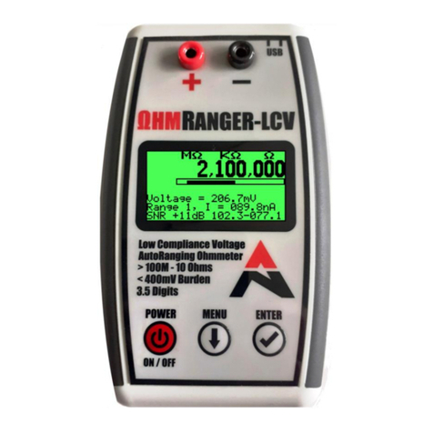
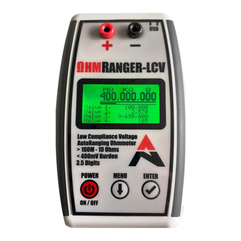
ALTONOVUS NanoRanger User manual

1
NR-01 Instruction Manual V2.3 Revised 05 Jan 20
Instruction Manual
NR-01 Auto-Ranging Direct Current (DC) Ammeter

2
NR-01 Instruction Manual V2.3 Revised 05 Jan 20
Disclaimer
NanoRanger is a factory-calibrated, highly accurate ammeter, intended for measuring low levels
of current. It is aimed at the hobbyist and professional User. NanoRanger is not intended to
replicate the full functionality of bench equipment. Instead, it aims to provide a portable and most
affordable means of measuring low current levels, during the development of power-efficient
designs. It is not intended to and should NOT be used to measure current levels above 0.8A.
If used in any manner other than that expressly set out in AltoNovus product documentation,
warranties granted by AltoNovus shall be deemed void and AltoNovus shall not be liable for any
claims or damages arising out of product use or malfunction.
Although every effort is made to ensure the accuracy of NanoRanger, no guarantee of accuracy
is given or implied.
Users may reproduce and store this document for personal use. For wider permission requests,
email the publisher, addressed “Attention: Permissions Coordinator,” at info@altonovus.com
Trademarks
The name NanoRanger is Copyright © 2019 AltoNovus Limited. NanoRanger will be a
registered Trademark of AltoNovus Limited.
Document Revisions
DATE
VERSION NUMBER
DOCUMENT CHANGES
15 Nov 19
2.2 (Software Release 1.12)
Launch Release
05 Jan 20
2.3 (Software Release 1.12)
Added notes to Section 5
Approvals
Release and / or amendment of this document requires the following approvals:
NAME
ROLE TITLE
Geoff Dean
Managing Director
Steve Thickett
Technical Director

3
NR-01 Instruction Manual V2.3 Revised 05 Jan 20
TABLE OF CONTENTS
1 Preface................................................................................................................................4
1.1 The User..............................................................................................................................4
1.2 Conventions Used in This Manual.......................................................................................4
1.3 Explanation of Safety Warnings...........................................................................................4
1.4 Obtaining Documentation and Information..........................................................................4
2 NanoRanger .......................................................................................................................5
2.1 Utility and Employment........................................................................................................5
2.2 Theory of Operation.............................................................................................................5
2.3 Technical Data.....................................................................................................................6
2.4 Compliance..........................................................................................................................7
2.5 Guide to Product..................................................................................................................7
2.6 Understanding the User Interface........................................................................................8
2.7 Device Set-Up .....................................................................................................................8
2.8 NanoRanger Menu Structure.............................................................................................10
3 Safety................................................................................................................................13
3.1 Using NanoRanger Safely .................................................................................................13
3.2 Guide to Graphical Symbols..............................................................................................14
4 Taking Manual Readings ................................................................................................16
4.1 Switching NanoRanger On .............................................................................................16
4.2 Automatic Range-Switching............................................................................................16
4.3 Setting the Range Limit...................................................................................................17
4.4 The Signal to Noise Ratio (SNR)....................................................................................17
4.5 Maximum and Minimum Readings .................................................................................17
4.6 Power Off........................................................................................................................18
5 Taking PC-Controlled Readings - SCPI.........................................................................18
5.1 SCPI Mandated Commands...........................................................................................18
5.2 SCPI Required Commands.............................................................................................19
5.3 Device Commands..........................................................................................................19
6 Storage, Transportation and Disposal ..........................................................................23
6.1 Storage ..............................................................................................................................23
6.2 Packaging and Transportation...........................................................................................23
6.3 Disposal.............................................................................................................................23
7 Maintenance.....................................................................................................................24
7.1 Replacing the Batteries......................................................................................................24
7.2 Cleaning.............................................................................................................................24
7.3 Recalibration......................................................................................................................24

4
NR-01 Instruction Manual V2.3 Revised 05 Jan 20
Preface
1.1 The User
NanoRanger is not a toy. It is a precision instrument and should be treated accordingly. It is aimed at the
hobbyist, maker and professional User community. This Manual assumes a level of technical expertise on
the User’s part. NanoRanger should not be used by those without a knowledge of safe working on
electronics. This Manual covers the use and operation of NanoRanger. It does NOT cover calibration or
maintenance, as these are not activities that the User can perform.
1.2 Conventions Used in This Manual
The following style conventions are used in this document:
Courier New
SCPI System control inputs and outputs.
User input variables
< > Angle brackets surround User-supplied values.
1.3 Explanation of Safety Warnings
CAUTION! Indicates a hazard with a low level of risk which, if not avoided, could result in damage to
NanoRanger and / or minor injury to Users.
1.4 Obtaining Documentation and Information
1.4.1 Internet
The latest version of the documentation is available at the following address: http://www.altonovus.com.
1.4.2 Ordering Documentation
Documentation, User instructions and technical information can be ordered by emailing:
1.4.3 Documentation Feedback
We welcome your comments and ideas, which may be incorporated in our NanoRanger FAQs page. Any
comments, requests for clarification, or suggestions for future Versions of this document can be submitted
to: info@altonovus.com.

5
NR-01 Instruction Manual V2.3 Revised 05 Jan 20
2 NanoRanger
2.1 Utility and Employment
NanoRanger is an accurate, affordable, auto-ranging DC ammeter for the measurement of very low
currents. As people strive for more efficiency from new and existing products, the measurement of current
consumption of devices is becoming more critical. Previous solutions to this challenge ranged from very
expensive ammeters (thousands of pounds), to cheaper solutions that only have limited manual ranges.
The NanoRanger is a solution to these challenges, as it provides a 3.5-digit, 9 range ammeter that can
switch over 8.5 decades (from 800mA to 1nA), with resolutions down to 10pA. It features:
•A 128 x 64mm LCD display, giving a wealth of information about the User’s current readings.
•This large 11-digit display shows the User mA, uA, nA, pA, all on one line.
•A SNR display shows how much noise, or AC, is present on the current signal.
•A range bar shows which range the User is in, plus the minimum / maximum range settings.
•Minimum and maximum ranges can be adjusted to limit the auto-ranging, or just to fix it at 1 range.
•An automatic Power Off timer, and configurable LED backlight, enables the User to maximise
battery life.
Readings are completed approximately every 300mS, with samples collected every 170uS and averaged
out over 200mS to remove most of the mains noise associated with circuits (50Hz and 60Hz).
An averaging mode allows the User to run the sampling for however long the User chooses. When
finished, it reports the average current, time, and total charge in mAh or smaller. This enables the User to
use it to measure the charge of specific events; e.g. a device coming out of Standby to make a radio
transmission.
2.2 Theory of Operation
NanoRanger is powered by 2 x AA batteries (not supplied), generating approximately 3V. This is fed into a
buck-boost power converter to produce 3.3V that powers the system. NanoRanger will continue to work
down to approximately 2V on the batteries.
Pressing the Power On button starts the NanoRanger. Pressing the Power On button again powers off
the NanoRanger. Standby current, when powered off, is approximately 10nA.
The current to be measured is connected through the Positive and Negative terminals of the NanoRanger.
Current must flow from the Positive terminal to the Negative terminal.
A switch bank selects the appropriate load resistor to put across the terminals. The current flowing through
the terminals generates a voltage across the resistor. If the voltage increases beyond 45mV, then the load
resistor is switched to a higher current resistor and the readings are restarted.
The voltage across the load resistor is amplified by a x50 amplifier and filter, before entering an Analogue
to Digital Converter (ADC).

6
NR-01 Instruction Manual V2.3 Revised 05 Jan 20
The ADC is 12-bit, which then oversamples and automatically averages to produce a 16-bit result.
Samples are taken approximately every 170uS. These are then built up over a period of 200mS to average
out and eliminate most mains-based noise (50 and 60Hz). Factory set calibration compensation is applied
to the result, to give an accurate reading. The reading is displayed on the LCD, which takes approximately
60mS to update. A new reading is then started.
A range produces readings up to approximately 2500. If the reading is below 150, then the range is
switched down before starting the next reading. If the reading is above 2150 at any time, then the range
switches up immediately and the reading is restarted.
Fast up-range switching is needed when a device under test comes out of standby mode. The
NanoRanger can switch up a range in less than 30uS and change from the lowest to the highest range in
approximately 200uS.
Down-range switching is initiated after a reading has been completed and when the reading is below the
down-range threshold. This is so that the User achieves a complete reading if the current is switching
quickly between ranges (fast up, slow down).
The minimum and maximum range settings can be adjusted so that no range switching down or up will
occur.
2.3 Technical Data
UNIT
PHYSICAL PARAMETERS
Weight (incl batteries)
Approximately 200g
Length x Width x Depth
148 x 90 x 30 mm
Accuracy specifications +/- % of range:
RANGE
RESOLUTION
BURDEN
VOLTAGE
RESISTANCE
ACCURACY
20.00nA
10pA
< 0.05V
2M
< 1%
200.0nA
100pA
< 0.05V
200K
< 0.5%
2.000uA
1nA
< 0.05V
20K
< 0.3%
20.00uA
10nA
< 0.05V
2K
< 0.3%
200.0uA
100nA
< 0.05V
200R
< 0.3%
2.000mA
1uA
< 0.05V
20R
< 0.3%

7
NR-01 Instruction Manual V2.3 Revised 05 Jan 20
20.00mA
10uA
< 0.05V
2R
< 0.3%
200.0mA
100uA
< 0.05V
0R2
< 0.3%
800mA
1mA
< 0.05V
0R05
< 0.5%
•Burden voltage is for full 2500 fixed range. Range switching occurs at around 0.045V.
•Current consumption LCD Light on < 15mA.
•Current consumption LCD Light off < 10mA.
•Current consumption Powered-off < 10nA.
•Typical operating time on one set of 2 x AA batteries is > 150 hours.
UNIT
OPERATIONAL PARAMETERS
Temperature
0 –50C
Humidity
10 –90% Non-Condensing
2.4 Compliance
NanoRanger is certified as CE and FCC compliant. A supporting Technical File is available to Competent
Authorities.
2.5 Guide to Product
A - Positive Terminal
B - Negative Terminal
C - Display Screen
D - On / Off Button
E - Menu Navigation
F - Select Button
G - USB Interface
H - Battery Compartment
H

8
NR-01 Instruction Manual V2.3 Revised 05 Jan 20
2.6 Understanding the User Interface
A - The current reading, displayed in mA, uA, nA, and pA. In this example, 0.309uA.
B- The small, lower Range Bar shows which ranges are in use. The upper, longer Range Coverage Bar
shows movement across the ranges during the reading. The box surrounding both shows what range
constraint has been input via the menu. In this example, none.
C- The Signal to Noise Ratio (SNR). The SNR indicates how much (Min and Max) noise,
variation, and AC components are in the signal, followed by Maximum and Minimum samples
during the reading.
D- Maximum (Mx) and E – Minimum (Mn). The Mx and Mn readings are the largest and smallest
that have occurred since measurement started. Below that, the maximum and minimum samples
are shown.
2.7 Device Set-Up
2.7.1 Fitting 2 x AA Batteries
1. Remove battery compartment cover, by applying gentle pressure
to the finger pad.
2. Ensure clean contacts on batteries.
3. Insert new batteries, observing polarity instructions in battery
compartment:
4. Replace battery compartment cover.
Note: 2 x AA alkaline batteries will give in excess of 150 hours of continuous operation. Treat and dispose
of all batteries in accordance with manufacturer’s instructions.

9
NR-01 Instruction Manual V2.3 Revised 05 Jan 20
2.7.2 Removing the Protective Film
If desired, remove the protective film from the front of the NanoRanger unit.
Peel carefully from below the Positive and Negative terminals.
NanoRanger will still function normally if the User chooses to leave the film in place.
2.7.3 Attach Feet (if desired)
NanoRanger is supplied with 4 rubber feet, for Users requiring added stability. Attach these with
due regard to the areas that will experience pressure during normal use; i.e. the Keypad buttons
and Terminals. Attaching the Feet as shown below will improve the stability of NanoRanger
during use.
2.7.4 Connecting User Probes
Using User-supplied Probes, connect the Positive terminal (RED) to the higher voltage side of the
current to be measured. Connect the Negative terminal (BLACK) to the lower voltage side of the
current to be measured. Current must flow from Positive to Negative, for the NanoRanger to
function:

10
NR-01 Instruction Manual V2.3 Revised 05 Jan 20
2.7.5 Controls
Firstly, ensure batteries are fitted in accordance with 2.7.1 (above). Three buttons control the operation of
the NanoRanger; Power, Menu, and Select. Pressing the Power button will start the NanoRanger. Two
start-up screens will display whilst loading the code:
One with the AltoNovus logo:
The second with battery voltage*, software release (here ALT-1.11), NanoRanger serial number
(here 1933200), calibration date and load status. Measurement can then commence (See
Section 4).
* Note: the most accurate indication of remaining battery life will be at device Powerdown.
2.8 NanoRanger Menu Structure
NanoRanger has several features accessible through the Menu. Press the Menu button to exit measuring
and enter the menu mode. The screen below will appear:
Pressing the Select button will take the User back to measuring mode. Pressing the Menu button will
scroll through the menu options. The Menu options are currently:
•Measure.

11
NR-01 Instruction Manual V2.3 Revised 05 Jan 20
•Range Maximum.
•Range Minimum.
•Measure Average.
•Advanced.
These Menu options may change in the future. NanoRanger software updates will be available from time
2.8.1 Measure
The Measure feature performs a measurement, as described in Section 4.
2.8.2 Range Max
This feature sets the maximum range to move up to. Press the Select button to scroll through the ranges.
2.8.3 Range Min
This feature sets the minimum range to move down to. Press the Select button to scroll through the
ranges.
2.8.4 Measure Average
This feature calculates an average current over a longer period. The display is not updated until the Select
button is pressed to stop the average reading:

12
NR-01 Instruction Manual V2.3 Revised 05 Jan 20
The following screen will then be displayed:
•The average current is shown over the period. In this case, 31.1uA.
•The sample time is shown in multiples of 200mS. In this case, 18.85 seconds.
•The total charge for the period is shown. In this case, 162.410nAh.
•The maximum (Mx) and minimum (Mn) 200mS samples in the period is shown.
When taking an average reading, the range should not be changed, as this will affect the results. Ensure
that the minimum and maximum ranges are set to the range that will cover the largest current expected.
2.8.5 Advanced Menu
Configuration in this menu is saved to Non-Volatile memory and restored on Power up. This feature gives
two options:
•Powerdown that enables the automatic Power Off timer. Timer starts at the last key press.
Options are; Off, 30mins, 1hr (Default), 2hrs, 4hrs, and 8hrs.
•LCD Light that enables / disables the LCD backlight.

13
NR-01 Instruction Manual V2.3 Revised 05 Jan 20
3 Safety
CAUTION! NanoRanger is designed to measure low levels of current. Do not expose to excess load.
Excess load can result in component failure.
3.1 Using NanoRanger Safely
3.1.1 Environmental Conditions:
•NanoRanger is not intrinsically hazardous. Users should take the same care when using
NanoRanger as they would with any other device that measures live electric currents.
•NanoRanger should not be connected to leads (USB, probe) greater than 3M in length.
•NanoRanger should not be exposed to:
oExcess moisture, condensing humidity, or liquid
oShock
oExcess Load
oHeavy weights
oPressure to the screen area
oExtremes of temperature (accuracy will be impacted)
3.1.2 Technical Life Span:
•NanoRanger is guaranteed for a period of 2 years from the date of purchase.
•Periodic (every 1 year) recalibration is recommended to ensure continuing maximum accuracy
(see Section 7.3 ‘Recalibration’).
3.1.3 General Safety Information:
•Users should continue to observe usual safe working practices when using NanoRanger.
•NanoRanger is intended to be used in a controlled environment, to measure levels of current
within its operating range (<800mA).
•If in doubt, Users should check current levels with another instrument before employing
NanoRanger to obtain higher accuracy readings. NanoRanger does not incorporate overcurrent
protection, as this would inhibit accuracy at low current levels.
•NanoRanger uses a flame-retardant enclosure (Hammond 1553 series), Fire Class UL 94 HB.

14
NR-01 Instruction Manual V2.3 Revised 05 Jan 20
•NanoRanger meets CE and FCC standards for radiated emissions and susceptibility to
emissions.
3.1.4 Product Limitations and Restrictions:
•NanoRanger is a cost-effective means of obtaining highly accurate readings of current. However,
while every care is taken to ensure accuracy, no guarantee of accuracy is given or implied.
3.1.5 Installation Safety Information:
•NanoRanger is delivered ready for use. With temperature variation in transit, Users should allow
the device to acclimatise to the operating environment before use.
3.1.6 Maintenance Safety Information:
•NanoRanger is not User-serviceable, or repairable. If NanoRanger should fail to operate
satisfactorily during its warranty period, please contact AltoNovus through the website to arrange
repair or replacement.
3.2 Guide to Graphical Symbols
3.2.1 Explanation of Safety Information on the Packaging and Product
SYMBOL
MEANING
Waste of Electrical and Electronic Equipment (WEEE) recycling. Dispose of
electronics correctly.
Mark of compliance with European Union legislation and regulations.
Mark of compliance with Federal Communications Commission requirements.
Battery polarity indicator. The User’s serial number is also on this label, which is
found inside the battery compartment.

15
NR-01 Instruction Manual V2.3 Revised 05 Jan 20
3.2.2 Explanation of Graphical Symbols in this Instruction Manual
SYMBOL
MEANING
Do not immerse in, or expose to, liquid.
Avoid extremes of temperature.
Precision electronic instrument.
Do not drop.
Do not subject to heavy weights or excess pressure.
No User-serviceable parts.
Do not open unit.
Do not exceed maximum load.
Only use a clean, dry cloth to clean unit.

16
NR-01 Instruction Manual V2.3 Revised 05 Jan 20
4Taking Manual Readings
4.1 Switch NanoRanger ON
Fit the batteries and connect User probes in accordance with the instructions at Section 2 above. Pressing
the Power button will start the NanoRanger.
Following start-up, NanoRanger will take 1073 samples to build up a reading over 200mS. This is
undertaken to eliminate mains noise at both 50Hz and 60Hz and to give an accurate average over the
period. By the time processing and displaying this information on the LCD is completed, the NanoRanger
averages about 3 readings per second.
Looking at the screen above, the User can see that it displays the current in mA, uA, nA, and pA. In this
example, 31.0nA.
4.2 Automatic Range-Switching
The range switches up (to a higher range) in approximately 30uS. When the current rises above 2150 in
whatever range the User is in, then the reading is immediately aborted, and the range increased. This
cycle is repeated until the range covers the input current. Note:If the maximum range is set, the range will
not automatically increase.
CAUTION! Care must be taken, as the burden voltage will increase and may result in damage, if
excessive voltages are encountered across the input terminals.
The range switches down when the completed reading is below 150. This is achieved so swiftly that range
switching does not occur going down ranges, but the User will see that the range has changed because of
a low value. For example, on powering up, the User will see the range bar move down over 2 seconds to
the bottom range, when nothing is plugged into the NanoRanger.

17
NR-01 Instruction Manual V2.3 Revised 05 Jan 20
The Value is displayed in a 4-digit format that also tells the User which range is in operation; e.g. 200.0nA.
4.3 Setting the Range Limit
Via the Menu, it is possible to define the range across which NanoRanger will operate. The range bar
underneath the digits shows which ranges are currently in use, moving left and right to confirm the range.
The range bar oscillates vertically after each reading to show how fast readings are occurring and to
provide visual confirmation that the device is functioning properly.
The rectangle around the range bar shows how far the range can move. In this example, it can cover all
possible ranges, but it is configurable with the Mx (maximum) and Mn (minimum) range functions and so
the User can fix and limit the range.
4.4 The Signal to Noise Ratio (SNR)
The SNR indicates how much noise, variation, and AC components are in the signal. It shows the
maximum and minimum samples that occurred whilst the NanoRanger was building up the reading. For
example, largest sample 31.8nA and smallest 30.3nA. In this case, the current is constant. The
explanation for noise is mains power at 50Hz being picked up by the test leads. When the minimum
sample hits 0then the reading may be invalid, due to missing data.
If this happens, the SNR will change to a negative contrast, as shown in the Power-Up screen below:
4.5 Maximum and Minimum Readings (Mx & Mn)
The Mx and Mn readings are the maximum and minimum readings that have occurred since the User
started measuring; e.g. maximum 31.1nA and minimum 31.0nA. These values will be reset on exiting the
measuring function.

18
NR-01 Instruction Manual V2.3 Revised 05 Jan 20
4.6 Power Off
Press the POWER button again, once readings are complete, to return NanoRanger to Standby mode.
Failing this, the Power Saver will do so, according to the timeframe that the User has specified.
5 Taking PC-Controlled Readings –SCPI
This device is SCPI compatible, but with limited functionality. Hence, it is not SCPI compliant and cannot
process commands whilst performing measurements. When entering SCPI commands, indicated by
Courier New font, only the portions with capital letters have to be entered; the remainder can be left out.
The commands below can be entered through the USB interface, via a COM port on a simple terminal
programme. Commands / responses are terminated with a Line Feed.
While NR-01 is USB enabled, the chip it uses converts output to Rs232. Set the baud rate to
57K6 on the port. AltoNovus uses Realterm as a terminal program. Again, set the port speed to
57K6.
5.1 SCPI Mandated Commands:
*CLS This command clears the event registers and queues.
*ESE This command sets bits in the Status Enable Register of the Standard Event Register.
*ESE? This command queries bits in the Status Enable Register of the Standard Event Register.
*ESR This command reads and clears the contents of the Standard Event Status Register.
*IDN? This command retrieves the identification string of the device:
AltoNovus,NanoRanger,nnnnnnn,yyyy
Where nnnnnnn = serial number
yyyy = software version
*OPC This command sets the operation complete (OPC) bit after all pending commands have been
executed.
*OPC? This command queries the OPC bit.
*RST This command resets the device settings to their default values.
*SRE This command sets or clears the bits of the Service Request Enable Register.
*SRE? This command queries the bits of the Service Request Enable Register.
*STB? This command collects the status byte of the device.
*WAI This command postpones the execution of subsequent commands, until all previous overlapped
commands are finished (Not Used).

19
NR-01 Instruction Manual V2.3 Revised 05 Jan 20
5.2 SCPI Required Commands:
SYSTem:ERRor[:NEXT]? This command returns the oldest unread error message from the event log and
removes it from the log.
SYSTem:ERRor:COUNt? This command returns the number of errors in the event log.
SYSTem:VERSion? This command queries the present SCPI version.
STATus:QUEStionable[:EVENt]? This command reads the Questionable Event Register.
STATus:QUEStionable:ENABle This command sets the contents of the Questionable Event Register.
STATus:QUEStionable:ENABle? This command reads the contents of the Questionable Event Register.
STATus:PRESet This command resets all bits in the status model.
5.3 Device Commands:
The commands below are used to control the functionality of the NanoRanger. When a NanoRanger is
powered up, it is controlled via the front panel buttons. In this mode, it will output its measurement through
the USB in the form below. All currents are in units of Amperes and all power measurements in units of
Ampere Hours:
+6.4E-10<CR><LF>
This will be output continuously. In the example above, it is 0.64nA.
To enable the device to be controlled via SCPI, a *RST command must be issued. This will stop all output
and the operation of the device until it receives commands telling it what to do.
5.3.1 Save (*SAV) and Recall (*RCL)
*SAV This command will save all the changes the User has made into flash memory, so that they can be
recalled at a later time.
*RCL This command will retrieve the saved changes made. When entering SCPI mode with *RST the
device will be in its default state.
5.3.2 Power Off (SYSTem:POWer)
SYSTem:POWer This command will turn the NanoRanger off, similar to the power button on the front panel.
5.3.3 LCD Backlight (CONFigure:LED)
CONFigure:LED <0,1>This command will turn the LCD backlight LED On or Off.0 = off, 1= On. For
example:
CONFigure:LED 0 This command turns the backlight LED Off.

20
NR-01 Instruction Manual V2.3 Revised 05 Jan 20
CONFigure:LED? This command returns the backlight LED status. For example:
CONFigure:LED?
1
5.3.4 Powerdown Settings (CONFigure:POWerdown)
CONFigure:POWerdown <0..5>This command sets the timer to automatically Powerdown. Any
command received through the USB interface will restart the timer. The options are:
0= Off
1= 30 minutes
2= 1 hour
3= 2 hours
4= 4 hours
5= 8 hours
CONFigure:POWerdown? This command will return the current Powerdown timer setting.
5.3.5 Range Settings (CONFigure:RANge)
CONFigure:RANge <0..8>This command sets the range of the NanoRanger. There are 9ranges, as
detailed below. Do Not subject the NanoRanger to currents above the selected range, as this may damage
the device: 0= 20.00nA
1= 200.0nA
2= 2.000uA
3= 20.00uA
4= 200.0uA
5= 2.000mA
6= 20.00mA
7= 200.0mA
8= 800mA
CONFigure:RANge? This command returns the current range setting of the NanoRanger, as well as the
maximum and the minimum ranges. For example:
CONFigure:RANge? 7,8,7
Current range is 7, maximum range is 8, minimum range is 7.
CONFigure:RANge:MAXimum <0..8> This command sets the maximum range of the NanoRanger. On
Powerup, or *RST the maximum range will be 8.
Other manuals for NanoRanger
1
This manual suits for next models
1
Table of contents
Other ALTONOVUS Measuring Instrument manuals
Popular Measuring Instrument manuals by other brands

Texmate
Texmate UM-40-ACV user manual

BRONKHORST
BRONKHORST IQ+Flow series instruction manual

Bushnell
Bushnell 74-0100 instruction manual

BW Technologies
BW Technologies GasAlertQuattro 3 Operator's manual

Apera Instruments
Apera Instruments LabSen 763 user manual

Kingspan
Kingspan Watchman Radar installation instructions