manuals.online logo
Brands
  1. Home
  2. •
  3. Brands
  4. •
  5. Altox
  6. •
  7. Automobile Accessories
  8. •
  9. Altox TRACKER-4 User manual

Altox TRACKER-4 User manual

O p e r a t i o n a l M a n u a l
ALTOX TRACKER-4
General Guide for Installation
- Install the device as far as possible from metal parts and wiring
harnesses.
- For better receiving of GPS-GLONASS signals direct the upper part of the
device casing to the windshield minding metal obstacles.
- Recommendation: connect device supply directly to the OBD-II connector
wires where pin 16 is +12В, pin 4 is GND (common).
Please indicate the place of ALTOX module's location in the vehicle for
possible maintenance:
Authorized Service:
Installation Date:
Altox
SMS Status Messages:
Date: 01.01.16 - current date
Time: 00:00:00 (UTC) - current time
GSM (0-31): 28 - GSM receive signal level (not less than 10)
GPS: 15,0 - number of satellites and HDOP parameter
Speed: 0km/h - current speed
Volt: 12.8V - car-system voltage
I/O: 0,0,0 - IN, OUT1 and OUT2 status
http://google.com/maps - link to the current location in Google Maps
Specifications
LED
GSM-antenna
(adhesive tape)
GPS-antenna
(magnet)
LED status (in SIM card slot)
Solid - request to SIM card, searching/registration in the network
Slow blinking (once every 2 seconds) - waiting mode
Fast blinking (5 times every second) - establishing of GPRS/RING/SMS/USSD
General Information
Dear buyers of ALTOX equipment!
We thank you for purchasing a new ALTOX TRACKER-4 device. This device
will provide you with great options to control the location and routes of
your vehicle.
You need a SIM card for your ALTOX device. It is recommended to use
special plans for M2M equipment.
Use
Using ALTOX system you can remotely control the location of your vehicle
via SMS text messages and/or satellite monitoring system ALTOX SERVER
2.0 in the real-time mode (setting TRACKING1). If there is no GSM
connection, the device saves over 10,000 into embedded memory.
ALTOX device uses Wialon IPS v1.1 protocol which allows using other
monitoring systems that support this protocol.
Control and Programming
Algorithm for the connection of the device to the monitoring system:
- Register in ALTOX SERVER 2.0 or any other monitoring system that
supports Wialon IPS v1.1 protocol;
- If needed change server IP address and port in the device using
instructions SERVER1 and SERVER2, respectively;
- Ask your mobile provider for APN access point and set is up using SMS-
commands APN1, APN2, APN3;
- Ask device ID using SMS-command ID1 or Id2;
- Add a new item with this ID to the monitoring system.
Control via an outgoing call
Call the phone number of the SIM card installed in the GSM module.
The phone number you are using to make a call should already be saved in
the device (see text messages SMS-commands NUM1/2/3).
Saving of the first caller's phone number into cell NUM1 follows up
automatically (cell NUM1 should be empty).
When setting CALL1 is activated, ALTOX tracker responds to the call, then
you need to enter a DTMF-command :
- Switch ON/OFF OUT1 – press 1.
- Switch ON/OFF OUT2 – press 2.
- Request status message – press 3.
- Request account balance message – press 4.
After a minute the connection is dropped automatically.
If CALL0 setting is active, the incaming call is dropped, and OUT1 reverses
its state.
Red - Power Supply +12V (via fuse 1А)
Black - GND (General)
Pink - Input IN (connection of the button)
Blue - Output OUT2 (commutates at GND)
Grey - Output OUT1 (commutates at GND)
Please deactivate PIN code request
before inserting a SIM Card!
Parameter
Value
Power Supply Voltage
10V - 28V
Standby Current
less than 35mA
Max Current for Auxiliary Output Terminals
150mA
Operating Temperature
from -40 to +80°С
Control via Text Messages (SMS/TCP)
Send a text message (SMS) instruction to the phone number associated with
the SIM card installed in the module. Text message instructions can be sent
from any phone number. If the password is set (PASS), then before entering
any instruction, you should include its value with no spaces (for example,
«1111STATUS», where 1111 is password, STATUS is a command).
Messages are not case sensitive.
When sending instructions from server using TCP, add «cmd_» before
command (for example, cmd_ACTIVATE).
To request the account balance of the SIM card (by number from the BAL
setting) use SMS command «USSD». If you need to request data for another
phone number, add it in the command: «USSD:*XXX#».
To send a text message from the phone number associated with the SIM
card in the tracking device, use «SMS:NNN:XXX»,where NNN is the phone
number to which a text message should be sent to, and XXX is a text
message.
If there is a response SMS is received, the tracker will forward it back to
the phone number from which the latest correct text message instruction
has been sent or to the phone number from NUM1/2/3 (see setting SMSF1).
SMS with GSM Stations Data:
The text message contains 7 cells with data: N, MCC, MNC, LAC and CID.
N - number of cell from 0 to 6 (if a cell is empty, all fields have value 0);
MCC - Mobile Country Code;
MNC - Mobile Network Code;
LAC - Local Area Code;
CID - Cell ID.
LAC and CID fields values are displayed in hexadecimal notation.
MCC, MNC, LAC and CID data allow to determine the location of the vehicle
on the map (using Google, Yandex services, etc.).
Attention! LAC and CID fields values are displayed in hexadecimal notation
Note: after the setting of the APN point, ALTOX tracker will switch into
GPRS mode. To capture movement history send instruction TRACKING1. In
this mode, Internet traffic amounts to not more than 30MB per month
without taking rounding off into account.
To automatically switch off the data transfer in roaming use setting
«PING2:0».
SMS with ID and General Settings:
ID:12345678901234 - Unique Device Identificator
P500,0 K1 S1:v11.0 - PULSEIN:500,PULSEOUT:0, KEEPOUT1, SMSF1,SMSV:11
C1 P"" - CALL1, PASS: (up to 4 characters)
N1"" - phone number cell NUM1
N2"" - phone number cell NUM2
N3"" - phone number cell NUM3
B"*100#":10,5:1 - BAL:*100#, BTIMER1:10, BTIMER2:5, TRANSLIT1
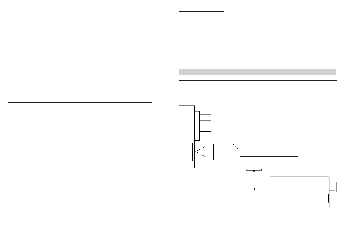
SMS with ID and Internet Settings:
ID:12345678901234 - Unique Device Identificator
S"XXX.X.X.X","XXX" - SERVER1:XXX.X.X.X, SERVER2:XXX
G"apn","user","pass" - APN1:apn, APN2:user, APN3:pass
C3,2 P30,30, T0:10 - COUNT1/2, PING1/2, TRACKING0,TMOTION:10
F5,10,15,60 R90,90 - FREQ1/2/3/4, ROAM1/2
Control
Command
Request SMS with the device status
STATUS / LOCATION
Switch on auxiliary output OUT1
ACTIVATE / OUTPUT_ON
Switch off auxiliary output OUT1
DEACTIVATE / OUTPUT_OFF
Switch on auxiliary output OUT2
ACTIVATE2 / OUTPUT_ON2
Switch off auxiliary output OUT2
DEACTIVATE2 / OUTPUT_OFF2
Additional Instructions
Command
Send USSD-request *XXX# using the module's SIM card
USSD:*XXX#
Send text message ХХХ from SIM card's number to NNN
SMS:NNN:XXX
Request GSM stations data (MCC,MNC,LAC,CID)
GSMINFO
Internet Settings
Command
APN Access Point (ask your mobile provider)
APN1:internet
APN User Name (ask your mobile provider)
APN2:login
APN Password (ask your mobile provider)
APN3:password
Internet-application server's IP address
SERVER1:X.X.X.X
Internet-application server's port
SERVER2:XXX
Number of attempts to establish GPRS before reconnect
COUNT1:3
Number of attempts to establish TCP before reconnect
COUNT2:2
Ping frequency in home network, 1-99 sec
PING1:30
Ping frequency in roaming, 0-99 sec (0-OFF)
PING2:30
Tracking mode (committing routes to the system)
TRACKING1 /0
Settings for the TRACKING1 mode
Command
Switching threshold moving/parking, km/h
TMOTION:10
Transmission frequency in motion (0-50km/h), 1-99sec
FREQ1:5
Transmission frequency in motion (50-100km/h), 1-99s
FREQ2:10
Transmission frequency in motion (>100 km/h), 1-99sec
FREQ3:15
Transmission frequency when parked, 0-9999sec (0-OFF)
FREQ4:60
Transmission frequency in motion (roaming), 0-999sec
ROAM1:90
Transmission frequency when parked (roaming), 0-9999s
ROAM2:600
6. CALL0 setting switches the module into the mode of dropping
incoming calls which allows saving money (in this case output OUT1
reverses its state)..
7. To set up a password for each text message command send
PASS:XXXX to the device where XXXX is a 4-characters-long password.
8. Using SMS-commands NUM1, NUM2 and NUM3 save in the device
authorized phone numbers. Phone numbers should be entered in the
international format.
Attention! Authorized phone numbers should not have caller identity
restriction (the number should not be hidden), otherwise the device will
drop the call.
9. Use BAL:XXX, where XXX is the request account balance number, to
save the phone number to request account balance status via USSD.
10.Setting BTIMER1:N (where N is a number of days) sets the period of
time for automated account balance requests using USSD (BAL setting) and
sending the response to the first authorized phone number NUM1 / NUM2 /
NUM3.
This option allows automated control of the account balance SIM card of
the device.
To switch off this option send a text message command with value 0
(BTIMER1:0)
11. Setting BTIMER2:N (where N is a number of hours) is similar to
setting BTIMER1, with one exception: the response with the account
balance information is sent to the server equipment (TCP connection).
Attention! When USSD is used to request account balance information GPRS
session might be closed which can result in rounding off of Internet traffic.
Settings
You can enter several settings simultaneously, dividing them by commas.
If the password is set (PASS:XXXX), then before entering any instruction,
you should include its value with no spaces (XXXXSETTINGS1).
Messages are not case sensitive.
When sending instructions from server using TCP, add «cmd_» before
command (for example, cmd_SMSF1).
1. To change the signal reporting time at input IN send PULSEIN:XX,
where XX is value in ms.
This setting prevents false triggers when sensors with a long period of
contact chatter are connected.
2. For pulse signals send SMS-command «PULSEOUT:XX» to the device's
SIM card number, where XX is the duration of the signal in seconds from 1
to 9999 value.
This instruction switches auxiliary output OUT1 into the pulse mode.
To switch OUT1 back into normal operation mode use the same command
with value 0 (PULSEOUT:0).
3. Setting KEEPOUT1 activates the option to save and to subsequently
restore of auxiliary output OUT1 state when the device's power supply is
switched off and then switched on, respectively.
To switch off this option send SMS-command KEEPOUT0 to the device.
4. By default, the device uses the option of forwarding all incoming
SMS text messages (SMSF1 setting) that are not commands to the phone
number used to send the last correct command or the the phone number
set up for the device NUM1, NUM2 or NUM3.
The text of the forwarded text message includes sender's phone number in
the first line and the text of the message.
To switch off this option send SMS-command SMSF0 to the device.
5. In the waiting mode the device controls the car system voltage.
When the heater is turned off and the voltage drops below the predefined
value XX (see settings, instruction SMSV:XX, where XX - threshold voltage),
the system will send an alarm SMS text message to the first authorized
phone number entered into settings (see settings, commands NUM1, NUM2,
NUM3).
The next alarm SMS text messages about the voltage drop will be sent
every 3 hours.
General Settings Instructions
Command
Request SMS with device ID and settings 1
ID1 / SETTINGS1
Request SMS with device ID and settings 2
ID2 / SETTINGS2
Restore to factory default settings
SETDEFAULT
Technical Settings
Command
Pulse time of the input signal IN, 1-9999ms
PULSEIN:500
Pulse mode for OUT, 0-OFF (0-9999 sec)
PULSEOUT:0
Restoring of the state for OUT after power supply
KEEPOUT1 /0
Forwarding of incoming SMS (to switch off use SMSF0)
SMSF1 /0
SMS about car system voltage drop
SMSV:11.0
CALL1 - response incoming call, CALL0 - dropping call
CALL1 /0
Setting the password before entering SMS-commands
PASS:XXXX
Save the phone number into cell NUM1
NUM1:+YYYYYYY
Save the phone number into cell NUM2
NUM2:+YYYYYYY
Save the phone number into cell NUM3
NUM3:+YYYYYYY
Save USSD number fore account balance requests
BAL:*XXX#
Timer for sending SMS with balance, 0-99 days (0-OFF)
BTIMER1:10
Timer for sending balance into application, 1-9 hours
BTIMER2:5
Transliteration of cyrillic characters
TRANSLIT1 /0

Other Altox Automobile Accessories manuals

Altox WBUS-4 v2 Quick start guide

Altox

Altox WBUS-4 v2 Quick start guide

Altox TRACKER-5 User manual

Altox

Altox TRACKER-5 User manual

Popular Automobile Accessories manuals by other brands

Whispbar K900 installation instructions

Whispbar

Whispbar K900 installation instructions

Axxess AXDSPL-FD3 installation instructions

Axxess

Axxess AXDSPL-FD3 installation instructions

Toyota THF 30 owner's manual

Toyota

Toyota THF 30 owner's manual

Thule 2021 parts list

Thule

Thule 2021 parts list

Haba 4703220 manual

Haba

Haba 4703220 manual

Bundutec BUNDUCUBE owner's manual

Bundutec

Bundutec BUNDUCUBE owner's manual

NavLinkz RL2-MBN45 manual

NavLinkz

NavLinkz RL2-MBN45 manual

Kargo Master 4A82T installation guide

Kargo Master

Kargo Master 4A82T installation guide

Warn 83680 installation instructions

Warn

Warn 83680 installation instructions

Mopar 82204700 instructions

Mopar

Mopar 82204700 instructions

Front Runner TRCA008 manual

Front Runner

Front Runner TRCA008 manual

Rhino-Rack RTD25L instructions

Rhino-Rack

Rhino-Rack RTD25L instructions

Metra Electronics 95-7617B installation instructions

Metra Electronics

Metra Electronics 95-7617B installation instructions

Koso BA053001 instructions

Koso

Koso BA053001 instructions

Menabo DELTA Fitting instructions

Menabo

Menabo DELTA Fitting instructions

Thule 1705 instructions

Thule

Thule 1705 instructions

Fiamma 98655-713 Installation instruction

Fiamma

Fiamma 98655-713 Installation instruction

Audiovox LCMR6CT installation manual

Audiovox

Audiovox LCMR6CT installation manual

manuals.online logo
manuals.online logoBrands
  • About & Mission
  • Contact us
  • Privacy Policy
  • Terms and Conditions

Copyright 2025 Manuals.Online. All Rights Reserved.