manuals.online logo
Brands
  1. Home
  2. •
  3. Brands
  4. •
  5. Altox
  6. •
  7. Automobile Accessories
  8. •
  9. Altox WBUS-4 v2 Quick start guide

Altox WBUS-4 v2 Quick start guide

O p e r a t i o n a l M a n u a l
ALTOX WBUS-4 v2
General Guide for Installation
- Install the device as far as possible from metal parts and wiring
harnesses.
- Recommendation: connect device supply directly to the OBD-II connector
wires where pin 16 is +12В, pin 4 is GND (common).
- Auxiliary output OUT commutates at +12V. It is used to start heaters using
an analogous signal and to connect status LED located in the button from
the package, as well as to connect a coolant pump or the interior's heater
via a power relay.
Auxiliary output OUT is switched on with the delay (TIME2 setting) and/or
based on the coolant agent temperature (LTEMP1 setting) after the heater
is switched on. It is switched off with the delay (TIME3 setting) after the
heater is switched off.
- If there are other control units on the bus, it is recommended to connect
the module's control wire (blue) via normally open signaling relay
controlled by output OUT.
In this case you should activate setting SEPARLINE1 that activates this relay
before the data exchange.
- If you need to implement additional options of remote control of output
OUT (for example, to block engine remotely) activate setting SEPAROUT1.
It switches the output mode into manual control mode (SMS-commands:
ACTIVATE / DEACTIVATE).
In this mode setting KEEPOUT1 activates option to save and to
subsequently restore of output OUT state when the module's power supply
is switched off and then switched on, respectively.
Please indicate the place of ALTOX module's location in the vehicle for
possible maintenance:
Authorized Service:
Installation Date:
Altox
SMS Status Messages:
HEATER ON 30min - heater status and time until switching off
GSM (0-31): 28 - GSM receive signal level (not less than 10)
Voltage: 12.8V - car-system voltage
Temp heater: 50С - heater's temperature sensor's value
Flame: no - heater's flame sensor's value
Output: off - auxiliary output OUT status
Note: if relevant data is not available, the fields will not be filled in
Text Messages with Error Codes:
Error code: none - stored codes of the heater's errors
Note: in ТТС there are 3 error cells, FF response means there are no errors
Specifications
LED
LED status (in SIM card slot)
Solid - request to SIM card, searching for network connection
Slow blinking (once every 2 seconds) - waiting mode
Fast blinking (5 times every second) - establishing of GPRS/RING/SMS/USSD
Installing a Button to Switch on the Module
Make a Ø8mm hole in the plug or in another easily accessible for a driver
place. The button is connected in accordance with the color of the main
connector wires (key: Input IN - +12V, LED: output OUT - resistor - GND).
Note: if a non-latching button (FIXKEY1 setting) is used to switch heater on
heater will not be switched off automatically after time specified in TIME1.
General Information
Dear buyers of ALTOX equipment!
We thank you for purchasing a new ALTOX WBUS-4 v2 device. This device
will provide you with great options to control your autonomous starting
parking heater.
You need a SIM card for your ALTOX device. It is recommended to use
special plans for M2M equipment.
Use
Using ALTOX system you can control your starting pre-heater remotely
using a phone. You can use all mobile and landline phones with tone dialing
option. Certain types of mobile phones (smart phones) can use apps and
the option of using web interface to control the system in the real-time
mode.
Control and Programming
You can start using your ALTOX module right after you have saved
authorized phone numbers in settings (3 cells: NUM1 / NUM2 / NUM3).
Saving of the first caller's phone number into cell NUM1 follows up
automatically (cell NUM1 should be empty).
To save other phone numbers use a text message command NUMX:+YYYYY,
where X is a number from 1 to 3, and +YYYYY is a phone number.
To clear the cell send NUMX instruction without specifying a phone number.
There are the following control options:
- Outgoing voice call and DTMF commands;
- Outgoing text messages (SMS instructions);
- Mobile applications Thermo Call, HeaterRC or others;
- Direct control via a button in the car's interior;
- Via web interface of the mobile Internet app http://altox.ru/app
Control via an outgoing call
Call the phone number of the SIM card installed in the GSM module. The
phone number you are using to make a call should already be saved in the
device (see text messages SMS-commands). If the call is made using a
number that has not been saved in the ALTOX module, the connection with
the device will end without receiving a response signal. The working status
of the heater will not change.
When setting CALL1 is activated, ALTOX responds to the call and plays
voice prompts (option).
If this setting is not active (CALL0), the call is dropped after a certain
number of ringing tones. 1 ringing tone - the heater switches on,
2 ringing tones - the heater switches off.
Parameter
Value
Power Supply Voltage
10V - 28V
Standby Current
less than 20mA
Max Current for Auxiliary Output Terminals
150mA
Operating Temperature
from -40 to +80°С
Red - Power Supply +12V (via fuse 1А)
Black - GND (Common)
Pink - Input IN (connection of the button)
Blue - WBUS
Grey - Auxiliary output OUT (commutates at +12V)
Please deactivate PIN code request
before inserting a SIM Card!
Following voice prompts you should enter a DTMF-command by pressing a
relevant tone button:
- Switching the autonomous heater ON/OFF – press 1.
- Request account balance – press 2.
- Request heater status – press 3.
After a minute the connection is dropped automatically.
The parking heater will be ON for the specified in settings time period
(TIME1), and additionally LED on the button installed in the car will be
activated.
Control via Button
The standard ALTOX equipment also includes a button (it is installed if
required in the car's interior). This button controls the heater and indicates
its current working status.
Control via Internet
This option allows controlling the heater in the real-time mode via
Internet-app ALTOX HEATER (http://altox.ru/app) using your phone's or
tablet's browser. Detailed recommendations on setting up the Internet-app
and switching the module to the GPRS mode can be found in the document
«Description of ALTOX HEATER Internet-application».
Attention! If you decide not to use the option of controlling the heater via
Internet after switching the module into the GPRS mode, you should switch
the GPRS mode off by sending a text message command «APN1:».
Control via SMS
Send a SMS-command to the phone number associated with the SIM card
installed in the module. Text message commands can be sent from any
phone number. If the password is set (PASS setting), then before entering
any command, you should include its value with no spaces (for example,
«1111START», where 1111 is password, START is an command).
When setting SEPAROUT1 is activated, the auxiliary output OUT is switched
into a manual control mode (to implement additional options).
Note: after the setting of the APN point, ALTOX module will switch into
GPRS mode. Internet traffic amounts to less that 3MB not taking rounding
off into account. To automatically switch off the data transfer in roaming
use setting «PING2:0».
Text SMS with General Settings:
A0 R1 B0 T30,0,0 - HEATER-A0, RSTOP1, BIND0, TIME1/2/3
L0,0 F0 S0,0 K0 - LTEMP1/2, FIXKEY0, (SEPAR)OUT0/LINE0, KEEPOUT0
S1:w0,e1 - SMSF1, SMSW0, SMSE1
C1 P"" - CALL1, PASS: (up to 4 characters)
N1"" - phone number cell NUM1
N2"" - phone number cell NUM2
N3"" - phone number cell NUM3
B"*100#":10,5:1 - BAL:*100#, BTIMER1:10, BTIMER2:5, TRANSLIT1
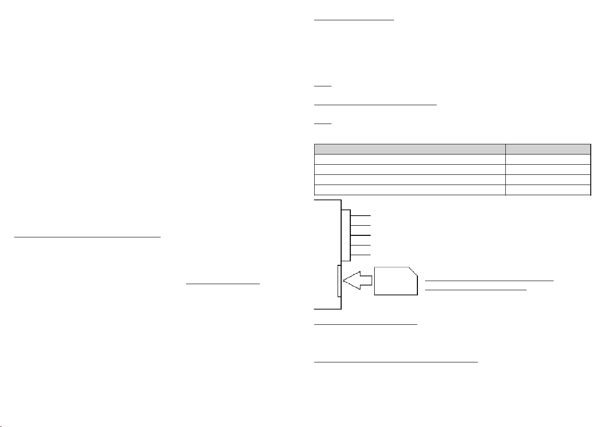
Text SMS with ID and Internet Settings:
ID:12345678901234 - Unique Device Identificator
S"XXX.X.X.X","XXX" - SERVER1:XXX.X.X.X, SERVER2:XXX
G"apn","user","pass" - APN1:apn, APN2:user, APN3:pass
C3,2 P30,30 - COUNT1/2, PING1/2
Text SMS with GSM Stations Data:
The text message contains 7 cells with data: N, MCC, MNC, LAC and CID.
N - number of cell from 0 to 6 (if a cell is empty, all fields have value 0);
MCC - Mobile Country Code;
MNC - Mobile Network Code;
LAC - Local Area Code;
CID - Cell ID.
LAC and CID fields values are displayed in hexadecimal notation.
MCC, MNC, LAC and CID data allow to determine the location of the vehicle
on the map (using Google, Yandex services, etc.).
Internet Settings
Command
APN Access Point (ask your mobile provider)
APN1:internet
APN User Name (ask your mobile provider)
APN2:login
APN Password (ask your mobile provider)
APN3:password
Internet-application server's IP address
SERVER1:X.X.X.X
Internet-application server's port
SERVER2:XXX
Number of attempts to establish GPRS before reconnect
COUNT1:3
Number of attempts to establish TCP before reconnect
COUNT2:2
Ping frequency in home network, 1-99 sec
PING1:30
Ping frequency in roaming, 0-99 sec (0-OFF)
PING2:30
Auxiliary Output Control
Command
Switch ON only the auxiliary output OUT
ACTIVATE
Switch OFF only the auxiliary output OUT
DEACTIVATE
Heater Control
Command
Switch the heater ON (operation time from TIME1)
START
Switch the heater ON for a time period of ХХmin (10-120)
START:XX
Switch OFF the heater
STOP
Request a text message (SMS) with the heater status
STATUS
1) By default, the module uses the option of forwarding all incoming
SMS that are not commands to the last phone number registered in the
module or entered into cells NUM1/2/3.
To deactivate this option use commands SMSF0.
2) Automatic SMS notifications (1-ON, 0-OFF):
SMSW1 - transmitting SMS status when the heater's status changes;
SMSE1 - notifications about heater's operation errors.
3) CALL0 setting switches the module into the mode of dropping
incoming calls which allows saving money.
4) NUM1/2/3 commands set up authorized phone numbers. Phone
numbers should be entered in the international format.
5) BTIMER1:N allows receiving an automated SMS with account balance
information every N days. To switch off this option send a SMS command
with value 0 («BTIMER1:0»).
To request the account balance of the SIM card (by number from the BAL
setting) use SMS command «USSD». If you need to request data for another
phone number, add it in the command: «USSD:*XXX#».
Note: MCC, MNC, LAC and CID data allow to determine the location of the
vehicle on the map (using Google, Yandex services, etc.).
LAC and CID fields values are displayed in hexadecimal notation.
Note: diagnostics is only possible for digital heaters.
Settings
You can enter several settings simultaneously, dividing them by commas.
If the password is set (PASS:XXXX), then before entering any instruction,
you should include its value with no spaces (XXXXSETTINGS1).
1) On the first launch the module automatically detects the type of the
digital heater. For the forced change of the connected heater's type use
text message instruction HEATER-XX, where XX:
A0 – Automatic determination of the heater's type (digital/analog);
А1 - Analog heater; W1 – Thermo Top C/Z/V/EVO/VEVO;
W2 – Thermo Top V/VEVO; W3 – WTT Emulation;
W4 – Timer 1533 Emulation; W5 – Telestart (ver.1) Emulation;
W6 – Telestart (ver.2) Emulation; W7 – Ventilation (summer mode).
2) To change the default operation time of the heater use text message
command TIME1:XX, where XX is operation time from 10 to 120 minutes.
3) If output OUT controls ventilation of the car's interior set up the
delay time for switching on output OUT using setting TIME2:XX and/or set
up switching of output OUT based on the coolant temperature using setting
LTEMP1:XX, where value ХХ can be from 0 to 99°С (0 - the setting is OFF).
4) LTEMP2:XX setting allows switching the heater off based on the
coolant temperature before the operation time TIME1:XX.
Attention! LTEMP1/2 are available not for all heater models.
Additional commands
Command
Send USSD-request *XXX# using the module's SIM card
USSD:*XXX#
Send text message ХХХ from SIM card's number to NNN
SMS:NNN:XXX
Request GSM stations data (MCC,MNC,LAC,CID)
GSMINFO
Heater's Diagnostics
Command
Read heater's errors
READ
Erase heater's errors
ERASE
General Settings Commands
Command
Request a text message (SMS) with general settings
SETTINGS1
Request a text message (SMS) with Internet settings
SETTINGS2
Restore to factory default settings
SETDEFAULT
User Settings
Command
Forwarding of incoming SMS (to switch off use SMSF0)
SMSF1 /0
SMS status when the heater's status changes
SMSW1 /0
SMS about control bus errors
SMSE1 /0
CALL1 - response incoming call, CALL0 - dropping call
CALL1 /0
Setting the password before entering SMS-commands
PASS:XXXX
Save the phone number into cell NUM1
NUM1:+YYYYYYY
Save the phone number into cell NUM2
NUM2:+YYYYYYY
Save the phone number into cell NUM3
NUM3:+YYYYYYY
Save USSD number for account balance requests
BAL:*XXX#
Timer for sending SMS with balance, 0-99 days (0-OFF)
BTIMER1:10
Timer for sending balance into application, 1-9 hours
BTIMER2:5
Transliteration of cyrillic characters
TRANSLIT1 /0
Technical Settings
Command
Type of connected heater (see the description above)
HEATER-XX
Shut off heater when there are errors on digital bus
RSTOP1 /0
Binding to other control modules
BIND1 /0
Default operating time of heater, 10–120 min
TIME1:30
Delay before switching on of OUT, 1–20 min
TIME2:0
Delay before switching off of OUT, 1–9 min
TIME3:0
Switch off OUT by coolant temp, 0-OFF (0-99°С)
LTEMP1:0
Switch off heater by coolant temp, 0-OFF (0-99°С)
LTEMP2:0
Type of button: latching / non-latching
FIXKEY1 /0
Switching on of OUT when the digital bus is activated
SEPARLINE1 /0
Manual control of OUT (on/off)
SEPAROUT1 /0
Restoring of the state for OUT after power supply
KEEPOUT1 /0

Other Altox Automobile Accessories manuals

Altox TRACKER-4 User manual

Altox

Altox TRACKER-4 User manual

Altox TRACKER-5 User manual

Altox

Altox TRACKER-5 User manual

Popular Automobile Accessories manuals by other brands

Pioneer ND-BC20PA installation manual

Pioneer

Pioneer ND-BC20PA installation manual

ASENTO EV-COLC15L installation manual

ASENTO

ASENTO EV-COLC15L installation manual

Curt Manufacturing 58957 installation manual

Curt Manufacturing

Curt Manufacturing 58957 installation manual

Classic Accessories OVER DRIVE PolyPRO 3 instructions

Classic Accessories

Classic Accessories OVER DRIVE PolyPRO 3 instructions

AUSSIE TONNEAU ATR01058 installation instructions

AUSSIE TONNEAU

AUSSIE TONNEAU ATR01058 installation instructions

Fiamma Carry-Bike UL 48 Installation and usage instructions

Fiamma

Fiamma Carry-Bike UL 48 Installation and usage instructions

Dometic CAM1000 Installation and operating manual

Dometic

Dometic CAM1000 Installation and operating manual

Cruz 934-717 Assembly instructions

Cruz

Cruz 934-717 Assembly instructions

FILTRON K 1157 installation instructions

FILTRON

FILTRON K 1157 installation instructions

Rola 59307 Instruction guide

Rola

Rola 59307 Instruction guide

Crux ACPBM-77Z manual

Crux

Crux ACPBM-77Z manual

Thule Kit 3056 instructions

Thule

Thule Kit 3056 instructions

INDRA 190105A101 user guide

INDRA

INDRA 190105A101 user guide

Oris Tourer operating instructions

Oris

Oris Tourer operating instructions

Livoo TEA164 instruction manual

Livoo

Livoo TEA164 instruction manual

ACS Systems e4 00 3942 manual

ACS Systems

ACS Systems e4 00 3942 manual

Thule 28 manual

Thule

Thule 28 manual

WALMEC 40138 AL Mounting instructions

WALMEC

WALMEC 40138 AL Mounting instructions

manuals.online logo
manuals.online logoBrands
  • About & Mission
  • Contact us
  • Privacy Policy
  • Terms and Conditions

Copyright 2025 Manuals.Online. All Rights Reserved.