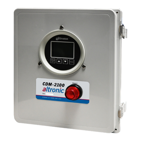
Altronic DE-2200 User manual

-1-
ALTRONIC COMPRESSOR MONITOR SYSTEM OPERATING INSTRUCTIONS
MODEL DE-2200 FORM DE-2200 IOI 09-01
WARNING: DEVIATION FROM THESE OPERATING INSTRUCTIONS MAY LEAD TO
IMPROPERENGINE/MACHINEOPERATIONWHICHCOULDCAUSEPERSONAL
INJURY TO OPERATORS OR OTHER NEARBY PERSONNEL.
1.0 OVERVIEW
1.1 For help locating subjects in this document, a section index is provided on page 37.
1.2 The Altronic DE-2200 compressor monitor system is an electronic microprocessor-based
systemdesignedtosensevariousanalogsensors,digitalswitchesandindustrystandardtype
J or K thermocouples to monitor industrial compressors. The system is field-programmable
using a PC (personal computer) and the supplied DE-2200 terminal program and contains a
non-volatile memory to store the setup. Serial communications provide an interface to PC’s,
PLC’s,modemsandsatelliteuplinksforremotecommunication. Abacklit4x20LCDcharacter
display shows system status, programmed engine/motor and compressor parameters and
channel labels. Afront mountedkeypad servesas theuser interface. TheDE-2200 provides
the safety shutdown functions needed to prevent unnecessary damage to remote operated
equipment. Additionally, the DE-2200 provides for remote data acquisition in a compact, low
cost package dedicated to industrial compressor applications.
1.3 Thesystemconsistsof threemainparts: apanelmountedDisplayModuleDE-2200,aPower
Supply Module 691122-1, and a Terminal Module 691136-1. These components are
interconnected by means of Cable assembly 693115-1.
WARNING: THE MONITOR SYSTEM MUST BE CONFIGURED PRIOR TO USE ON A
COMPRESSOR SYSTEM. REFERENCE DE-2200 PI PROGRAMMING
INSTRUCTIONS, FOR INSTRUCTIONS DESCRIBING HOW TO CONFIGURE THE
MONITOR FOR THE SPECIFIC APPLICATION. VERIFY THE PROGRAM IN
NONVOLATILE MEMORY (THE EEPROM) PRIOR TO STARTING THE SYSTEM.
REFER TO SECTION 10.0 ON HOW TO VIEW THE CURRENT CONFIGURATION.
2.0 DISPLAY MODULE
2.1 The Display Module serves as the user interface for the DE-2200 system. It is in a 6.5" x 6.5"
panel mounted enclosure and consists of an alphanumeric 20-character x 4-line backlit LCD
display,a16-key front-mountedkeypad,DB-25 D-SubandDB-9 D-Subconnectorsand three
pairs of serial port indicators.
2.2 The keypad is a sealed membrane unit that contains the familiar STOP, RESET and TEST
keys as well as other keys used to navigate through channel status and description, view
process screens, and to edit the configuration.
2.3 The LCD displays a “home screen” that displays a status line along with three user
configurable analog points; typical points are speed, the suction pressure and the discharge
pressure. A “view screen”, which is available by pressing the VIEW key, displays up to eight
user configurable analog process labels, values and bargraphs of the corresponding analog
inputs. Pressing the VIEW CHANNEL key displays the channel number, its timer status,
analog value (if applicable) and the corresponding 20-character user defined label.

-2-
2.4 The keypad, along with the LCD display, are used to navigate through channel status and
descriptions, view process screens, and to view or edit the system’s configuration. The
8UNITS or 9UNITS or the 6TENS or 7TENS keys areused to access channels by increasing
ordecreasing the channelnumbers by oneor by tenwitheachkeypress. PressingtheNEXT
key advances the display to the next screen or item. All menu adjustments are saved in non-
volatile EEPROM memory by pressing the ENTER key. The EEPROM memory retains the
current configuration during normal operation, after compressor shutdown and a system
power-down.
2.5 Three pairs of LED’s are provided on the back of the Display Module for troubleshooting
purposes, one Receive (RX) and one Transmit (TX) LED for eachport. TheTX LED will flash
when the Display Module is transmitting serial communications on the labeled port. The RX
LEDwillflashwhentheDisplayModuleisreceivingserialcommunicationsonthelabeledport.
3.0 POWER SUPPLY MODULE
3.1 The Power Supply Module is made to be rail mounted and is the interface between the
Terminal and Display Modules and to other systems. It typically plugs directly into the
Terminal Module using the DB-25 connectors and is held together with screws and screw
locks.
3.2 The Power Supply Module is made to accept up to four industry standard commercially
available0.6 inch plug-inOutput Modules. The OutputModulesprovide ameansof usingthe
DE-2200 monitor safety shutdown system status to interface with other systems on the
engine/motor and compressor. A typical application would be as a relay or solenoid coil
driver. TheOutputModules areoptically isolatedsolid-state switcheswhich areisolated from
power supply minus and engine ground. The Output Modules will be in the open (de-
energized) condition when the unit is unpowered. The output modules can be software
configuredforeithernormallyopen(N/O)ornormallyclosed(N/C)operationandhaveanLED
indicator associated with them. Outputs 3 and 4 are for use with the optional speed switch
and pre/post-lube features respectively. If an Output Module is programmed for normally
closed (energized for run), the LED will be ON in the normal run condition and OFF for a fault
condition. For Normally open configured modules the LED will be OFF for normal run
condition and turn ON for a fault condition.
The standard Output Modules’ outputs use the top row of the dual 16-position terminal strip
which is marked OUT 1 through OUT 4. Each of these outputs are fused with a replaceable
6.3 amp slow-blow fuse, Altronic P/N 601653. In addition to accepting industry standard
OutputModules,acustom AltronicOutputModuleP/N691124isavailablefortrippingignition
powered CD fuel valves and shorting CD ignition shutdown leads upon a fault. When both
functions are required, two of these modules are used as follows: OUT 1 slot must be used
to trip the fuel valve, and OUT 2 slot must be used to short the ignition. If 12-24 Vdc is lost
to the DE-2200 annunciator system, the custom Output Modules will trip the fuel valve and
short the ignition shutdown lead. This mimics the “fail-safe” operation of a normally closed
Output Module and therefore the LED will be ON in the normal run condition and OFF for a
fault condition. In programming the system, these modules are identified by using the
IGN/FUEL selection. Terminals IGN+ and IGN!are used to connect the shutdown lead, and
FV1 and FV2 are used for the CD fuel valve. A capacitor is included in the Power Supply
Module to supply the energy to trip the fuel valve.
3.3 The12-24VdcpowerfortheDE-2200systemisappliedtothepowersupplyterminalsmarked
(+) and (!) 12 - 24 VDC INPUT POWER. A 6.3 amp replaceable slow-blow fuse protects the
system from over currents, and a power LED lights when power is applied to the system.

-3-
3.4 The external connection for the two serial RS-485 communication ports is on the Power
Supply Module terminal strips. Port 2 is for RS-485 serial communication to Altronic
instruments, and port 3 is for RS-485 serial communication to a PC (personal computer) or
a PLC (programmable logic monitor) to perform remote monitoring or control functions if
desired.
3.5 Terminals marked IGN IN and PU IN are used by the DE-2200 system to detect either engine
rotation or ignition system firings. This input monitors changing signals such as those seen
oneithertheignitionshutdownleadoramagneticpickupmonitoringanenginemountedgear.
- The IGN IN terminal connects to the positive (+) C.D. ignition shutdown lead.
- The PU IN terminal connects to one magnetic pickup input; the other pickup wire
connects to the minus (!) terminal on the Power Supply Module.
NOTE: An installation may use only one of the terminals IGN IN or PU IN.
4.0 TERMINAL MODULE
4.1 TheTerminalModuleismadetoberailmountedand isthepoint ofinterfacebetween thefield
sensor wiring and the DE-2200 monitor system. A removable dual terminal strip is used for
the connection of the system to the equipment mounted discrete sensors which may consist
of up to 16 normally open or normally closed switches as well as up to 14 analog transducers
and 7 thermocouples selectable as type “J” or “K”. The 16 discrete sensor inputs are similar
to previous Altronic DA, DD, and DE annunciator systems and are numbered in the typical
annunciator format as 10-17, 20-27. The 14 analog inputs are numbered 30-37 and 40-45;
30-36 accept industry standard transducer signals in the range of 0-5 VDC. Inputs 37 and
40-45 accept 0-5 VDC transducers or industry standard type “J” or “K” thermocouples.
Connections from the Terminal Module to the Display Module are made using the 693115-x
series Cable Assembly.
44.2 TheDE-2200isdesignedtooperatewithindustrystandard,voltageorcurrentamplifiedoutput
transducers in the range of 0 to 5 Vdc or 0 to 25 mA. Four series of transducers are available
from Altronic: pressure transducers 691201-x, 691204-x and temperature transducers
691202/203-300, 691212/213-450.
4.3 PRESSURE TRANSDUCERS - The pressure transducers, Altronic P/N 691201-x and P/N
691204-x, are packaged in a rugged sealed case with a NPT pressure port, a corrosion
resistant media cavity, and a Packard Electric “Metri-Pack” connector. The ranges available
are 0-100, 300, 500, 1000, 2000, and 5000 PSIG for the 691201-x series and 0-50, 100, 300,
500 PSIA for the 691204-x series, all of which have an overload rating of 1.5 times full scale
without damage. The three wires from the transducer are: +5 volt excitation, +0.5 to 4.5 volt
output, and minus return. These three wires connect directly to the back of the Terminal
Module using cable assembly P/N 693008-x.
4.4 TEMPERATURETRANSDUCERS- Thetemperaturetransducers, AltronicP/N691202-300,
691203-300 with a temperature measurement range of +5 to 300EF and the 691212-450,
691213-450 with a temperature range of -40 to +450EF are packaged in a sealed, stainless
steel housing with a 5/8"-18 UNF threaded body, and a Packard Electric “Metri-Pack”
connector. During configuration the standard calibration for the 691202/203-300 sensor is
selected as "dEG1" and the standard calibration for the 691212/213-450 is selected by
choosing "dEG2". The three wires from the transducer are: +5 volt excitation, temperature
output voltage, and minus return. These wires connect directly to the Terminal Module using
cable assembly P/N 693008-x.

-4-
4.5 THERMOCOUPLE INPUTS - The terminal module accepts industry standard type “J” or “K”
thermocouplesoninputs37and40-45. Automatic coldjunctioncompensationisbuilt-in. The
units can be configured to EF or EC. Both a high and low setpoint is associated with each
channel.ThemonitorcanreadtypeJthermocouplesbetween!76EFand1382EF(!60ECand
750EC) and type K thermocouples between !76EF and +1472EF (!60EC and 800EC).
5.0 MOUNTING
5.1 DISPLAY MODULE - Mount the Display Module inside a control panel or to a suitable flat
surfaceso that thedisplay is ata convenient viewingheight. Adrilling template andmounting
dimensions are provided. NOTE: Avoid mounting the unit with the LCD display facing direct
sunlight. The display operating temperature range is !31EF to +176EF (!35EC to +80EC).
5.2 POWER SUPPLY MODULE - Mount the Power Supply Module in the panel either on the
bottom or the side of the main panel. The Power Supply Module is made to be rail mounted
onto commercially available 32 or 35 mm DIN mounting rails. It is also made to plug directly
into the Terminal Module using the DB-25 connectors and is held together with screws and
screw locks. Two end brackets P/N 610751 should be used to keep the modules from sliding
off the ends of the mounting rail.
As an alternative, the Power Supply Module and the Terminal Module can be mounted
separate from each other on theDIN mounting rails but in the same panel; in this case, a DB-
25 male/female cable such as P/N 693115-1 is used to electrically connect these modules.
The operating temperature range of the Power Supply Module is !31EF to +176EF (!35EC to
+80EC).
5.3 TERMINAL MODULE - Mount the Terminal Module in the panel either on the bottom or the
side of the main panel. The Terminal Module and Power Supply Module are made to be rail
mounted onto commercially available 32 or 35 mm DIN mounting rails. The Terminal Module
ismade toplug directlyinto thePower SupplyModuleusing theDB-25 D-Subconnectors and
held together with screws and screw locks. Two end brackets P/N 610751 should be used
tosecurethemodulesfromsliding offtheendsofthemountingrail. TheTerminalModuleand
the Display Module are electrically connected with a DB-25 male/female cable, 693115-x
series or equivalent. The operating temperature range of the Terminal Module is !31EF to
+176EF (!35EC to +80EC).
5.4 PRESSURE TRANSDUCER - Mount the pressure transducer in the panel or in a manifold or
tube off of the engine. Do not expose the pressure transducer to temperatures above 221EF.
(105EC).
IMPORTANT: Pressure transducers will withstand overloads as high as 1.5 times rated
pressure. If the overload rating is exceeded, failure may occur. Pressure fluctuations occur
in most reciprocating systems; pick the transducer with a rating high enough to prevent
overload by peak pressures of pulsations. It is recommended that a pressure snubber be
usedwhich willreduce thepeak pressureapplied tothe transducer. Thelife ofthetransducer
will be extended with the use of a snubber or pulsation dampener.
5.5 TEMPERATURE TRANSDUCER - Mount the temperature transducer in a thermowell on the
engine or machine. The actual sensor is located at the bottom of the transducer body; to
ensure accuracy, the tip of the probe should be surrounded by the measured media.
IMPORTANT: Do not exceed the absolute maximum rating of the transducers, 350EF
(176EC) for the 691202/203-300 or 450EF (232EC) for the 691212/213-450. Care should be
taken to protect the wiring and connectors from contact with hot surfaces.

-5-
6.0 WIRING (SEE WIRING DIAGRAMS)
6.1 SYSTEM COMPONENT WIRING - A DB-25 male/female cable, 693115-x series or
equivalent, is used to connect the Terminal Module to the Display Module and secured with
the cable lock screws. If mounted on the same mounting rail, plug the Terminal Module
directly into the Power Supply Module using the DB-25 D-Sub connectors at the ends of the
modulesandsecurethemtogetherwiththescrewsandscrewlockscaptivetotheconnectors.
If the Power Supply Module and the Terminal Module are mounted separate from each other
(must be mounted in the same panel) a DB-25 male/female cable such as P/N 693115-1 or
equivalent is used to connect these modules.
6.2 POWER WIRING - Connect the supply power wires to the 12-24 Vdc input power terminals
on the power supply, plus to terminal (+) and minus to terminal (!); power requirement is 12
to 24 Vdc (10 watts max.). The DC!terminal must be connected to panel ground which
should be the same as engine ground.
NOTE: This is the return path for normally open sensors and must be connected for proper
operation. DO NOT ground this device directly to the ignition system common coil ground.
6.3 SENSORWIRINGDISCRETEINPUTS-Thesensorleadsconnecttotheremovableterminal
strips on the Terminal Module. The terminal numbers correspond to the display numbers
which also have a user assigned 20 character label associated with it. The sensor inputs are
numbered similar to previous Altronic DA and DD annunciator systems: 10-17, 20-27. The
set ofterminals labeled Rand S arefor remoteReset andStop respectively,with PRE/POST-
LUBE disabled. With PRE/POST-LUBE enabled, Reset is wired to a lube switch. Sensor
inputs 10-27 can be user-configurable as class A, class B or class C logic. Any sensor point
can be wired for normally open or normally closed operation. Any unused sensor input must
contain a short jumper wire across the input.
- Normally Open (N/O) sensor switches are wired with one wire to the bottom terminal strip
oftherespectivesensornumberandtheothertoenginegroundwhichshouldbethesame
as power minus (!). A short jumper from the bottom terminal to the top terminal must be
connected for normally open sensors (see wiring diagrams).
- Normallyclosed(N/C) sensorswitchesare wiredwithone wiretothebottomterminalstrip
andthe otherto thetop terminalstrip ofthe respectivesensornumber. Note thatthe short
jumper wire must be removed.
- Remote stop and remote reset are wired the same as the sensor switches and can be
used with either normally open or normally closed contacts.
Use a wire size of between 16 AWG (max.) to 24 AWG (min.) to connect the sensor switches
to the terminal strip connector. Strip the insulation back 3/8"; twist the exposed wires tightly
together. Insert the exposed wire completely into the terminal strip and securely tighten the
clampingscrew. Wires runningto sensorswitches mustbe ingood conditionor replacedwith
new wires. When running wires, take care not to damage the insulation and take precautions
against later damage from vibration, abrasion, or liquids in conduits. An explosion-proof
conduit is not required. However; wires should be protected from damage by running them
in a protective conduit or in sheaths where appropriate. In addition, it is essential that the
following practices be adhered to:

-6-
6.3 (continued)
A. Neverrunsensor wiresin thesameconduitwithignitionwiringor otherhighenergywiring
such as the AC line power.
B. Keep secondary wires to spark plugs and other high voltage wiring at least eight inches
(200mm) away from sensor and sensor wiring.
C. Sensor switches may be connected to any passive device using contacts such as
standardswitchgauges,pressureorlevelswitches. DONOTconnectsensorleadstoany
voltage producing element.
D. In the case of a field conversion where sensors have previously been used with Murphy
tattletales,itisrecommendedthatthesensorsbecheckedfrequentlywhentheDEsystem
is first put into use. Sensor contacts may be burned or pitted from past exposure to
ignition system primary voltage. It is advisable to replace such sensors.
E. If it becomes necessary to check sensor switch to panel wiring with an ohmmeter or other
checker, first DISCONNECT the plug-in terminal strips from the Terminal Module.
Applying voltage to the DE-2200 system through the sensor leads may damage the
device. In addition, the area should be tested as non-hazardous before such testing
commences.
6.4 ANALOGSENSORWIRING-Foreachanalogmonitoredpointinputs30-37and 40-45select
a transducer - either an Altronic pressure or temperature transducer listed above or one that
outputs a signal in the range of 0 to 5 Vdc or 0 to 25 mA. Mount as described above. Use
cable assembly 693008-x or similar to wire transducer to the Terminal Module. All unused
inputs must be shorted with a short jumper wire. An internal 5 volt sensor supply (500 mA.
max.) is available to power the Altronic transducers; see wiring diagrams. If the 5 volt sensor
supply exits the panel it must be fused with a 0.5 ampere fuse. If 24 volt powered sensors are
used the 24 volt supply to them must be fused appropriately. Take care not to damage the
insulationwheninstallingandtakeprecautionsagainstlaterdamagefromvibration,abrasion,
or liquids in conduits. In addition, it is essential that the following practices be adhered to:
A. Neverrunsensor wiresin thesameconduitwithignitionwiringorotherhighenergy wiring
such as AC line power.
B. Keep secondary wires to spark plugs and other high voltage wiring at least eight inches
(200mm) away from sensor and sensor wiring.
6.5 THERMOCOUPLESANDTHERMOCOUPLEEXTENSIONWIRE-Groundedorungrounded
type J or K thermocouples may be used. Use thermocouple extension wire of the same type
as the thermocouple probe to connect the thermocouple to the temperature scanner. Use
stranded thermocouple wire having a good moisture-resistant insulation such as PVC; for
higherambienttemperatures,TeflonorB-fibreinsulatedthermocouplewireisrecommended.
To insure an accurate signal is transmitted to the instrument, avoid any added junctions,
splices and contact with other metals. All unused inputs must be shorted with a short jumper
wire. Take care not to damage the insulation when installing and take precautions against
laterdamagefrom vibration,abrasion,or liquidsinconduits. In addition,itis essentialthatthe
following practices be adhered to:
A. Neverrunthermocouplewiresinthesameconduitwithignitionwiringorotherhighenergy
wiring such as AC line power.
B. Keep secondary wires to spark plugs and other high voltage wiring at least eight inches
(200mm) away from thermocouples and extension wiring.

-7-
6.6 OUTPUT SWITCH WIRING - The Power Supply Module is made to accept an industry
standard 0.6 inch Output Module. The following modules are available from Altronic:
691124 This custom module has two uses: connection to a Murphy fuel valve and directly
grounding a C.D. ignition system.
- Use in position OUT 1 to connect to a C.D. ignition type Murphy fuel valve.
Connect terminals 3 and 8 of the fuel valve to the Power Supply Module
terminals marked F1 (FV1) and F2 (FV2).
- Use in position OUT 2 to directly ground-out (stop) a C.D. ignition system.
Wire the C.D. ignition shutdown lead and ignition ground to the Power Supply
Module terminals marked I+ (IGN+) and I!(IGN!) observing the proper
polarityfortheignitionsystem. DONOTconnectdirectly totheignitionsystem
common coil ground.
691125 Thismodule israted for 5-48Vdc,5.0 A.andmay be usedin any ofthe four output
slots OUT 1 through OUT 4.
NOTE: Use this module if it is desired to interrupt the DC supply to DC-powered
ignition systems such as Altronic CD1, CPU-90, II-CPU or DISN.
691056 Thismodule is ratedfor 5-60 Vdc,2.0 A.and maybe used inany of thefour output
slots OUT 1 through OUT 4.
691066 This module is rated for 5-200 Vdc, 0.67 A. and may be used in any of the four
output slots OUT 1 through OUT 4.
691065 This module is rated for 24-280 Vac, 2.0 A. and may be used in any of the four
output slots OUT 1 through OUT 4.
NOTE: Other industry standard 0.6 inch modules may be used as required.
6.7 RS-485COMMUNICATIONSWIRING-TherearetwoRS-485communicationportsavailable
on the DE-2200 system.
- Port 2 is for use with an optional Altronic DSM.
- Port 3 is for RS-485 serial communication to a PC (personal computer) or a PLC.
Useatwo conductorshielded cableoffine gaugestrandedwire andconnectthe wiresforport
2 to the terminals marked "A2" and "B2" and the shield wire to terminal “S2". The wiring for
port 3 connects to the terminals marked “A3", ‘B3" and “S3". Connect to the other
communication devices "A" to "A"(!) and "B" to "B"(+). Connect the shield wire to the DE-
2200 system ONLY.
6.8 TACHOMETER INPUT - Terminals marked IGN IN and PU IN on the Power Supply Module
are used by the DE-2200 system to detect either engine rotation or ignition system firings.
This input monitors voltage signals such as those seen on either the ignition shutdown lead,
ignition coil or a magnetic pickup monitoring an engine mounted gear.
- The IGN IN terminal connects to the positive (+) C.D. ignition shutdown lead.
- ThePUINterminalconnectsto onemagneticpickupinput;theotherpickupwireconnects
to the minus (!) terminal on the Power Supply Module.
NOTE: An installation may use only one of the terminals IGN IN or PU IN.

-8-
7.0 HAZARDOUS AREA OPERATION
7.1 The DE-2200 system is CSA certified for CLASS I, DIVISION 2, GROUPS C and D areas
when mounted in a suitable enclosure.
In addition, the following requirements must be met (see NFPA standard no. 493):
1. The low voltage sensor switch wires within the panel enclosure must be kept at least two
(2) inches away from other wiring. Run the sensor switch wires leaving the panel in a
separateconduit from allother wiring andkeepthem separate throughouttheinstallation.
2. Wiring to the sensors must have a grade of insulation capable of withstanding an AC
voltage of 500 volts RMS.
3. Sensorwiresmust berunin separateconduitsand junctionboxesfrom highvoltagewires
such as ignition, fuel valve, and other high voltage wiring.
WARNING: SUBSTITUTION OF COMPONENTS MAY IMPAIR INTRINSIC SAFETY AND/OR
SUITABILITY FOR CLASS I, DIV. 2, GROUPS C and D.
DO NOT DISCONNECT EQUIPMENT IN DIV. 2 ENVIRONMENT UNLESS POWER
IS SWITCHED OFF OR THE AREA IS KNOWN TO BE NON-HAZARDOUS.
8.0 KEYPAD DESCRIPTION
8.1 The DE-2200 monitor Display Module contains a sixteen-key sealed membrane keypad
whichisused tostop,reset andtestthe system. Theusercanalso viewprocessinformation
screens, view channel specifics, cancel timers, and view and edit pertinent operating
parameters.
8.2 STOP - The STOP key is used for a manual stop condition. By pressing the STOP key, the
monitor activates the configured output modules in the power supply.
8.3 RESET - The RESET key clears all past faulted points and resets all input and output timers
to their preset values.
8.4 TEST - The TEST key disables the output modules and allows the user to fault or test the
input sensors. Every time the test button is pressed, the test timer resets to its preset value.
8.5 CANCEL TIMERS - The CANCEL TIMERS key cancels all timers.
8.6 VIEW CHAN - The VIEW CHANNELS key allows the user to view the status of any input
channel and its user defined label.
8.7 NEXT- Fromthe VIEWscreen, allowsthe usertoviewthenextprocess informationscreen.
From the MENU screens, the next value to be edited.
8.8 VIEW - The VIEW key allows the user to view the process information screens.
8.9 ENTER - The ENTER key is used to accept a selectionand to save a new value in memory.
8.10 ESC - The ESCAPE key enables the user to exit any view channels or menu screens at any
time and return to the previous screen without changing programmed values.

-9-
8.11 MENU - The menu key allows the user to enter the edit menu. The global timers, input class
output assignment, output configuration and the time and date may be viewed and adjusted
using the MENU key.
8.12 UNITS/TENS - 8UNITS/9UNITS keys increase or decrease values by one. The
6TENS/7TENS keys increase or decrease values by ten. These keys are used to increase
or decrease channel numbers, timers and to move the pointer in the menu screen.
8.13 F1 - Function key F1 displays the hourmeter and servicemeter messages.
8.14 F2 - Function key F2 displays the time and date of the first fault.
8.15 F1 and F2 keys can be used in conjunction with other keys to implement custom functions.
9.0 UNDERSTANDING THE HOME SCREENS
9.1 The "home screens" are described as a series of screens used to display several of the most
critical operating parameters on one screen. All of the home screens provide a status word
on the upper line, and typically the engine speed on the second line, the suction pressure on
the third line and the discharge pressure on the fourth line. Other analog parameters may be
programmed in for the second, third and fourth lines.
Thestatuslinewillreadoneofthefollowing:TIMERSACTIVE, PRE-LUBE,RUNNING,TEST
XXX SEC, FAULT AL12, MANUAL STOP.
The LCD display always reverts back to one of the home screens after a keypad operation is
completed or the operation times out.
9.2 TIMERS ACTIVE - To start the engine, press the RESET button. The “TIMERS ACTIVE”
messagewill bedisplayedand remainsuntilallClassBandClassCinputshavebeenarmed.
During the time that the Class B and Class C timers are still active, manually purge and crank
the engine.
STATUS TIMERS ACTIVE
SPEED 330 RPM
SUCTION 102.3 PSIG
DISCHARGE 200 PSIG

-10-
9.3 PRE-LUBE- Ifthe PRE/POST-LUBEoption isselected whenconfiguring thesystemfromthe
PC, “PRE-LUBE” will appear on the status line when the remote RESET terminal is activated.
Output 4 on the power supply module will change state. This allows for activation of an
electricallycontrolledpre-lubepumpforaprogrammedtimeperiodpriortocranking.Afterthis
userprogrammedtimedelay,thestatuslinewilldisplay“TIMERSACTIVE”. Thetimersactive
message will remain until all Class B and Class C inputs have been armed. During the time
that the Class B and Class C timers are still active, manually purge and crank the engine.
Note: If the timers active timer is set to less than the pre-lube timer the display will read
“RUNNING” when the pre-lube timer lapses.
STATUS PRE-LUBE
SPEED 0 RPM
SUCTION 2.3 PSIG
DISCHARGE 200 PSIG
9.4 RUNNING- After allClass B andClass C pointshavetimed outand are beingmonitored, and
if no faults are detected, the home screen will show the “RUNNING” message. This is the
screen that will remain under normal operation.
STATUS RUNNING
SPEED 1000 RPM
SUCTION 102.3 PSIG
DISCHARGE 300 PSIG
When a programmed servicemeter interval has expired (the hours left reaches 0), a *
character will be displayed at the end of the STATUS word on the top line of the HOME
screen. Press the F1 key to view the hourmeter and servicemeter times. See section 16.0
HOURMETER SERVICEMETER For further information.
STATUS* RUNNING
SPEED 1000 RPM
SUCTION 102.3 PSIG
DISCHARGE 300 PSIG
F1
Press to
view
message

-11-
9.5 TEST - The TEST home screen is entered by pressing the TEST key. The TEST mode
disarms all outputs and may only be entered from the RUNNING mode. The test time
remaining is shown on the top line. See section 13.0 TEST MODE SCREENS for more
information.
TEST
press
to test STATUS TEST 600 SEC
SPEED 1000 RPM
SUCTION 102.3 PSIG
DISCHARGE 200 PSIG
9.6 FAULT - If a fault condition occurs, the “FAULT” message for the first faulted channel will
appear on the display and will remain there until it is acknowledged. The numbers one
through two, after “AL” (alarm), shows the output switch that is faulted. To again view the first
fault screen, press the VIEW CHAN key. If all of the faulted sensors have been cleared and
the RESET key is pressed, the class B, C and output timers will reset and the display will
return to the TIMERS ACTIVE home screen.
STATUS FAULT AL12
1ST FAULT
CHAN 24
LOW OIL PRESSURE
ESC
returns to
fault
home STATUS FAULT AL12
SPEED 0 RPM
SUCTION 102.3 PSIA
DISCHARGE 0 PSIG
VIEW
CHAN
press to
return to
1st fault
RESET
to clear faults,
reset timers &
outputs
NOTE: The reset function can also be implemented by using the external hardwire RESET/
PRE-LUBE input available on the Terminal Module. The behavior of the monitor system will
be determined by the programming selections made when configuring the system.

-12-
9.7 The“MANUALSTOP”messagewillsupersedealloftheabovehomescreensiftheSTOPkey
is pressed.
STOP
press
to stop STATUS MANUAL STOP
SPEED 0 RPM
SUCTION 102.3 PSIG
DISCHARGE 0 PSIG
NOTE:Thestop functioncanalso beimplementedremotely byusingtheexternalSTOP input
availableon theTerminal Module. Thebehavior ofthe monitorsystem will beidentical tothat
obtained by pressing the local STOP key on the Display Module.
10.0 VIEW PROCESS INFORMATION SCREENS
10.1 The process information screens can be accessed from any of the home screens (except the
test home screen) or from the view channel screen by pressing the VIEW key. There are four
process screens: screens one and three each display up to four user programmed process
variables; screens two and four display an analog bargraph associated with the previous
process variable screen. Thus, up to eight process variables can be displayed both digitally
and in bar graph format.
The analog values are monitored by a microprocessor on the terminal board and are
configured by using a PC and the terminal program . The bargraph end points are set by the
low and high setpoints of the safety shutdown function. Unused channel screens will not be
displayed.
STATUS RUNNING
SPEED 1000 RPM
SUCTION 102.3 PSIG
DISCHARGE 200 PSIG
from VIEW
press
NOTE: Screens one and two display in digital and bargraph form the first group of four
selected analog inputs.
SUCTION 102 PSIG
DISCHRG 100 PSIG
FILTER 10 PSIG
BOP 110 PSIG
then at VIEW
press to
view
bargraph

-13-
10.1 (continued)
SUCTION Lššššš H
DISCHRG Lšššššššššššššššššš H
FILTER Lššššššššššššššššššššššššššš H
BOP Lššššššššššššššššššššššššššššššššššš H
then at
bargraph
screen VIEW
press to
view
next
NOTE: Screens three and four display in digital and bargraph form the second group of four
selected analog inputs.
TEMP 1 180 EF
TEMP 2 250 EF
TEMP 3 300 EF
TEMP 4 320 EF
then at VIEW
press to
view
bargraph
TEMP 1 Lššššššššššššššš H
TEMP 2 Lššššššššššššššššššš H
TEMP 3 Lššššššššššššššššššššššš H
TEMP 4 Lšššššššššššššššššššššššššššš H
then at
VIEW
press to
view next
process ESC
press
To
escape
11.0 VIEW CHANNEL STATUS SCREENS
11.1 Use the VIEW CHAN key to enter the view channels screens. Once in the VIEW CHAN
mode, the user can view any channel’s details.
- The first line will be the monitor system status; “TIMERS ACTIVE”, “RUNNING”,
“FAULT AL12', or “MANUAL STOP”.
- The second line shows whether the input point is “ARMED” or “NOT ARMED”. Class A
points will always be armed; class B points become armed only after their timers have
timed out. Class C points arm when cleared or timer times out.
- The third line shows the channel number and an analog value of that input; if configured
for that channel.
- The fourth line shows the user entered 20 character channel description.

-14-
11.1 (continued)
Upon pressing the view channel key, channel 10 will be shown. The UNITS and TENS keys
allow the user to quickly navigate through the monitors channels. Use the 8UNITS or 9
UNITS keys to increase or decrease the viewed channel by one. Use the 6TENS or 7TENS
keys to increase or decrease the viewed channel by ten. To exit the VIEW CHAN mode,
press the ESC key. After five minutes with no keypad activity, the display will revert back to
the current home screen.
STATUS TIMERS ACTIVE
SPEED 330 RPM
SUCTION 102.3 PSIG
DISCHARGE 200 PSIG
from current home
screen VIEW
CHAN
press
STATUS TIMERS ACTIVE
NOT ARMED
CHAN 10
ENGINE OIL PRESSURE
to see channel 20 from
channel 10 →
TENS
press
STATUS TIMERS ACTIVE
ARMED
CHAN 20
MANIFOLD PRESSURE
to see channel 21 from
channel 20 ↑
UNITS
press
STATUS TIMERS ACTIVE
NOT ARMED
CHAN 21
LB MANIFOLD PRESSURE
to see channel 40 from
channel 21
→
TENS
press →
TENS
then
press UNITS
↓
then
press

-15-
11.1 (continued)
STATUS RUNNING
ARMED
CHAN 40 83 PSIG
COMP OIL PRESSURE
to see channel 41 from
channel 40 ↑
UNITS
press
STATUS RUNNING
ARMED
CHAN 41 10.5 PSIG
SUCTION PRESSURE
to exit view channels
mode ESC
press
12.0 SHUTDOWN OR FAULT STATUS SCREENS
12.1 Withtheenginerunningandthemonitorsystemmonitoringpoints,ifafaultoccurs,thedisplay
willshowthefirstfaultdetected. Thephrase“1STFAULT”and“AL12"willbedisplayed;“AL1"
is for the first output, “AL12" is for outputs one and two. The output or outputs configured for
that channel will trip. The first fault will stay displayed on the screen until it is acknowledged
by one of the keypad keys RESET or ESC. Use VIEW CHAN key to view the status of all
channels.
After all of the current faulted channels are displayed, the display will revert back to the first
fault. If no class A sensors are faulted, pressing the RESET key will clear all displayed faults
and return the display to the timers active home screen. All class B and C input timers and
the output timers will be reset. Pressing the ESC key when the fault screen is displayed will
return the display to the fault home screen. To again view the “first fault” from the fault home
screen, press the VIEW CHAN key.
STATUS FAULT AL12
1st FAULT
CHAN 24
HIGH LIQUID LEVEL 1
Upon a fault,
the first fault is shown. NEXT
press next
for another
fault
RESET
press to
reset
timers &
outputs
STATUS TIMERS ACTIVE
SPEED 330 RPM
SUCTION 102.3 PSIG
DISCHARGE 200 PSIG

-16-
12.2 When a fault occurs on an analog channel 30-46, a “HIGH” or “LOW” indication will
additionally be displayed as to whether the point faulted on a high or low setpoint.
STATUS FAULT AL12
1st FAULT HIGH
CHAN 42 300 EF
HIGH DISCHARGE TEMP
A high setpoint faulted
on an analog input. The
analog value and
“HIGH” are displayed.
RESET
press
reset to
clear fault
13.0 TEST MODE SCREENS
WARNING: TEST MODE DISARMS ALL OUTPUTS. ACTUAL FAULTS WILL DISPLAY BUT
WILL NOT TRIP THE SYSTEM ALARM AND SHUTDOWN OUTPUTS. USE
MANUAL STOP FOR EMERGENCY SHUTDOWN.
13.1 The test mode is used for testing sensors without tripping the outputs. The monitor system
stays in the test mode for a preset timed period. To enter the test mode, make sure the home
screen status line says “RUNNING”, and press the TEST key on the keypad. The status line
will display “TEST xxx SEC”; xxx being the remaining test time. To test an input, momentarily
fault a sensor. The display will show the faulted point, its description and “1st FAULT” for the
first point tested. To test another point press the TEST key, this will clear the tested sensor
from the display and will refresh the test timer to its full programmed test time.
TEST
press to
enter test
mode STATUS TEST 600 SEC
SPEED 1000 RPM
SUCTION 102 PSIG
DISCHARGE 200 PSIG
Test screen is shown
with no faulted points.
Test key was pressed
from the “RUNNING”
home screen.
STATUS TEST 525 SEC
1st FAULT
CHAN 24
LIQUID LEVEL STAGE 1
sensor point 24 is
tested. TEST
press
to test
another
sensor

-17-
13.2 When any of the analog channels 30-46 are tested, a “HIGH” or “LOW” indication will
additionally be displayed indicating whether a high or low setpoint was tested. The display
will show the current analog value for the channel selected.
STATUS TEST 530 SEC
1st FAULT HIGH
CHAN 33 5 PSIG
HIGH FILTER PRESS
A high setpoint was
faulted on an analog
input
13.3 If no sensors are faulted and the TEST key is pressed,the display will return to the test home
screen. The test timer will be reset and the home screen parameters and values will be
displayed.
TEST
press
test key STATUS TEST 600 SEC
SPEED 1000 RPM
SUCTION 102.3 PSIG
DISCHARGE 200 PSIG
No sensors faulted.
Test home screen is
displayed.
13.4 To exit the test screen, press either the ESC or RESET key. Pressing the ESC key takes the
user to the “STATUS RUNNING” home screen and does not reset the class B, C and output
timers. Pressing the RESET key takes the user to the “STATUS TIMERS ACTIVE” home
screen with the class B, C and output timers reset.
ESC
press
esc key STATUS RUNNING
SPEED 1000 RPM
SUCTION 102.3 PSIG
DISCHARGE 200 PSIG
No sensors faulted.
Running home screen is
displayed.
RESET
press
reset key STATUS TIMERS ACTIVE
SPEED 1000 RPM
SUCTION 102.3 PSIG
DISCHARGE 200 PSIG
No sensors faulted.
Timers active home
screen is displayed.

-18-
14.0 AUTO PRE-LUBE / POST-LUBE OPTION
14.1 If enabled, AUTO PRE-LUBE is initiated by either a local contact closure of the reset
terminals on the terminal board or by the receipt of the appropriate serial command string.
To enable pre-lube the AUTO PRE-LUBE / POST-LUBE option must be selected when
configuring the system from the PC. The pre-lube time can be set from 0 to 999 seconds.
Upon initiation of the external reset, OUTPUT #4 on the power supply module will be
activated and remain activated for the length of the pre-lube timer and up to the configured
pre-lube RPM setpoint. The display will show “STATUS PRE-LUBE” on the top line
indicating that OUTPUT #4 is active. Upon the time out of the pre-lube timer and the
configured pre-lube RPM setpoint OUTPUT #4 will normalize and the display will return to
“TIMERS ACTIVE” or if the timers active timer has timed out “RUNNING”. Pre-lube will be
aborted by the detection of any monitored fault or the activation of the STOP key. If the pre-
lube timer is set to zero the system will act as though auto pre-lube was not configured.
RPM must be at zero during the activation of the remote reset to activate the pre-lube timer.
14.2 If enabled, AUTO POST-LUBE is initiated by the detection of any monitored fault or the
activation of the STOP key.
Toenable the post-lube theAUTO PRE-LUBE /POST-LUBE option mustbeselected when
configuring the system from the PC. The post-lube time can be set from 0 to 999 seconds.
Upon the detection of any monitored fault or the activation of the STOP key, OUTPUT #4 on
the power supply module will be activated and remain activated for the length of the post-
lube timer. Upon the time out of the post-lube timer OUTPUT #4 will normalize. Pre-lube
can be aborted by activation of either the CANCEL TIMERS key or the RESET key. If the
post-lubetimerissettozerothesystemwillactasthoughautopost-lubewasnotconfigured.
A pre-lube / post-lube panel indicator can be tied to OUTPUT #4 indicating when the lube
pump is active.
15.0 SPEED SWITCH OPTION
15.1 A user configurable speed switch function is available to activate pumps etc. at a specified
speed. OUTPUT #3 on the power supply module will be activated by the speed switch. The
speed switch RPM is configured in the terminal program. Upon reaching the set speed,
OUTPUT #3 on the power supply module will be activated and remain activated as long as
theRPMisabovetheswitch setting. WhentheRPMgoesbelowtheswitch settingOUTPUT
#3 will normalize. There is a 10 RPM hysteresis at the switch point.
16.0 THE HOURMETER AND SERVICE METER
16.1 The hourmeter and the servicemeter are active with a speed signal from either the Ignition
or the pickup input located on the power supply. The range for the each meter is 99999
hours. The hourmeter counts up by one hour and the servicemeters count down by one
hour. There are 11 configurable servicemeters; the desired messages and service intervals
are selected when programming the DE-2200 system. The service hours can only be
changed by using the terminal program and the PC. The hourmeter can be pre-set or reset
by using the menu on the display module. The servicemeters can be reset using the F2 key.

-19-
16.2 Whenever a programmed servicemeter interval has expired (the hours left reaches 0), a *
character will be displayed at the end of the STATUS word on the top line of the HOME
screen. Press the F1 key to display the hourmeter then the servicemeter messages. The
servicemeter will show the hours remaining until a scheduled maintenance is required.
When a scheduled maintenance is due, the hours left will display 0.
STATUS* RUNNING
SPEED 1000 RPM
SUCTION 102.3 PSIA
DISCHARGE 300 PSIG
F1
Press to
view
message
HOURMETER / SERVICE
MESSAGE NUMBER:600
TOTAL HOURS: 8971
RUN TIME HOURS
8
UNITS
press to
change
number
HOURMETER / SERVICE
MESSAGE NUMBER: 601
HOURS LEFT: 100
CHANGE FILTERS
8
UNITS
press to
change
number
Proceed through the servicemeter messages to find the required service. The number of
hours left until the listed maintenance is due is displayed for each service message. There
areuptoelevenuserprogrammableservicemessages. Theservicemeteralertcanbereset
after the required service is performed by pressing the F2 key with the desired message
displayed. Each servicemeter message is individually reset.
HOURMETER / SERVICE
MESSAGE NUMBER: 602
HOURS LEFT: 0
OIL CHANGE REQUIRED
F2
press to
reset
hours left

-20-
17.0 VIEWING OR EDITING THE CONFIGURATION USING THE MENU MODE
17.1 The menu screens can be accessed from any home screen (except test) by pressing the
MENU key. The menu screens allow the user to view or edit safety shutdown functions, the
test time, the hourmeter functions, the time and date, the communications functions, view
the input class and configure the outputs. The monitor must beinitially configured using the
terminal program running on a PC connected to the RS-232 port on the back of the monitor.
Reference the programming instructions form DE PI for instructions on how to configure the
monitorsystem for aspecific application. The menuscreens are intendedto view oredit the
already programmed values in the field. Changes made in the menu are stored in
permanent memory and remain fixed until changed again. Listed below are the values that
can be viewed or edited:
A: EDIT SAFETY SHUTDOWN:
1. VIEW OR EDIT SETPOINTS.
- Edit analog setpoints 30-46
2. VIEW INPUT CLASS:
- Class A - no time delay on start-up.
- Class B - 10 to 999 seconds time delay on start-up before input is active.
- Class C - 1 to 999 minutes safe-until-first-met with a global time delay.
3. VIEW OR EDIT TEST TIME - from 1 to 999 seconds.
4. VIEW OR EDIT THE OUTPUT CONFIGURATION:
- N/O (Normally Open) - open in the normal run state and closes upon a fault
- N/C (Normally Closed) - closed in the normal run state and opens upon a
fault or loss of 12-24 Vdc input power.
- IGN (Ignition Shorting and Fuel Valve Trip Module, Altronic P/N 691124) -
open in the normal run state and closes upon a fault or loss of 12-24 Vdc.
5. ACTIVATION DELAY TIME - from 0 to 99 seconds.
B: HOURMETER FUNCTIONS:
1. VIEW OR EDIT HOURMETER FUNCTIONS - 00 through 11
C: COMMUNICATIONS:
1. NODE NUMBER - from 1 to 99 (default is 1).
2. PORT 1 - ASCII OR MODBUS RTU
2. PORT 3 - ASCII OR MODBUS RTU
D: VIEW or EDIT THE TIME AND DATE:
1. TIME or DATE
E: VIEW FIRMWARE REVISION
1. DISPLAY:
2. TERMINAL:
Table of contents
Other Altronic Measuring Instrument manuals
Popular Measuring Instrument manuals by other brands
BARTEC BENKE
BARTEC BENKE RVP-4 operating manual

General
General DSM403SD user manual
SIGLENT
SIGLENT SNA5000A user manual
DH Instruments
DH Instruments DUAL MID FLOW instruction sheet
Milltronics
Milltronics AIRANGER DPL PLUS quick start guide

PCB Piezotronics
PCB Piezotronics 3713B1230G/-0001 Installation and operating manual
