Altronic CDM-2100 User manual

Operating Manual
CDM-2100
Dierential Pressure Monitor
Form CDM-2100 OM 3-21

CDM-2100 OM 3-21
All rights reserved © ALTRONIC, LLC 2021 2
TABLE OF CONTENTS BY SECTION PAGE
1.0 OVERVIEW....................................................................................................................... 3
2.0 CDM−2100 PANEL .......................................................................................................... 3
3.0 CDM−2100 DISPLAY MODULE ........................................................................................ 3
4.0 MOUNTING THE PANEL .................................................................................................. 3
5.0 WIRING............................................................................................................................ 4
6.0 KEYPAD DESCRIPTION.................................................................................................... 4
7.0 UNDERSTANDING THE HOME SCREEN........................................................................... 4
8.0 INITIAL CONFIGURATION................................................................................................ 5
9.0 RS−485 COMMUNICATIONS ......................................................................................... 10
10.0 MODBUS REGISTER LISTS ............................................................................................ 11
TABLE OF FIGURES
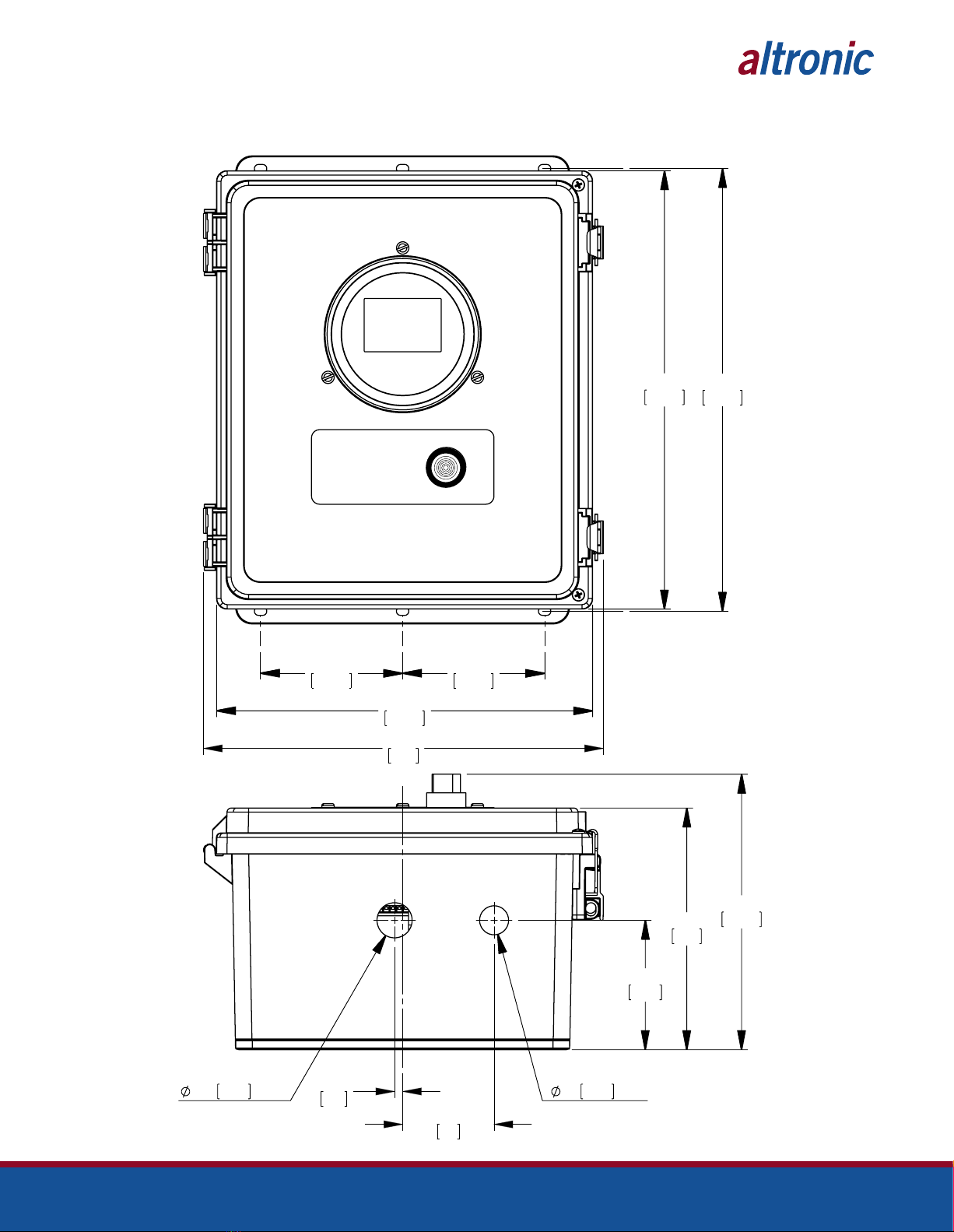
FIG. 1 MOUNTING DIMENSIONS ............................................................................................ 16
FIG. 2 WIRING DIAGRAM, CUSTOMER CONNECTIONS........................................................... 17
FIG. 3 FLOW CHART ............................................................................................................... 18
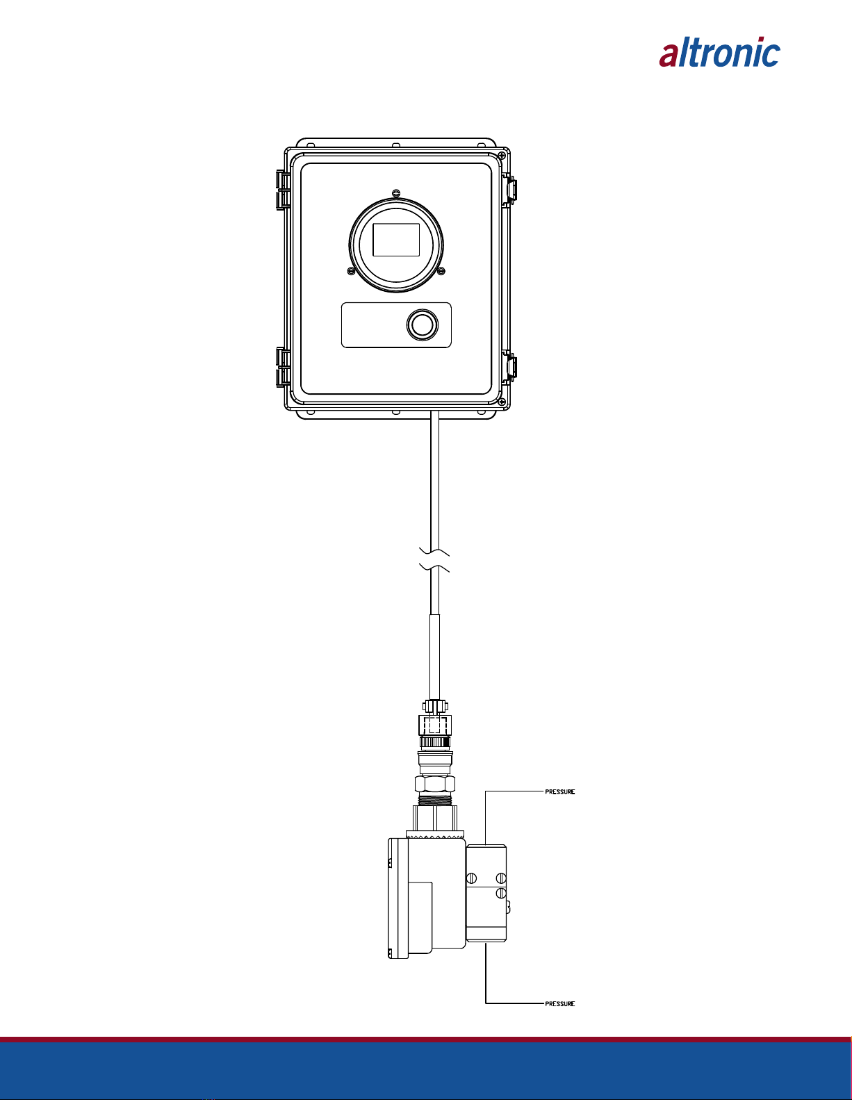
FIG. 4 CDM−2100 SYSTEM DIAGRAM..................................................................................... 19
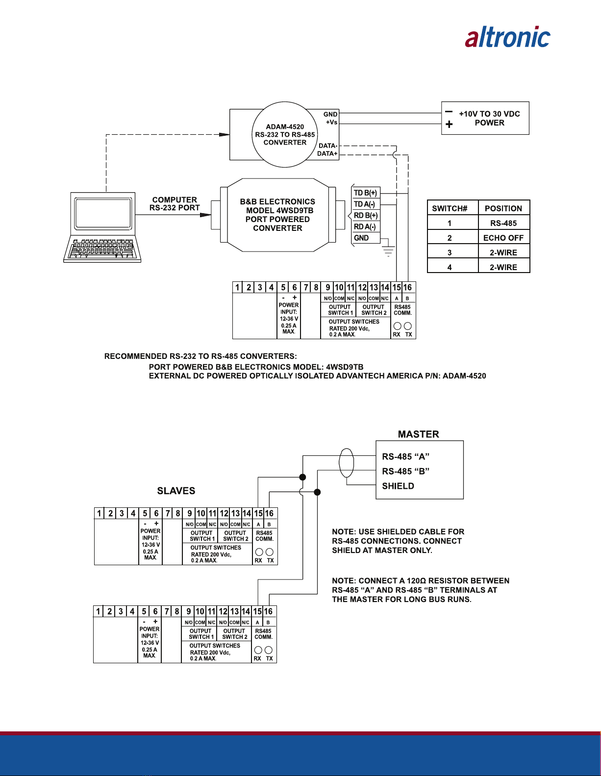
FIG. 5 RS−485 COMMUNICATIONS: PC HOOK−UP................................................................. 20
FIG. 6 RS−485 COMMUNICATIONS: MULTIPLE SLAVE UNITS................................................ 20

CDM-2100 OM 3-21
All rights reserved © ALTRONIC, LLC 2021 3
1.0 OVERVIEW
1.1 The CDM-2100 control panel consists of the DSG-1611DUPS instrument, wiring
terminals, and fuse installed in an industrial enclosure.
1.2 The CDM-2100 controller is a dedicated electronic microprocessor-based system
designed to sense dierential pressure across a single catalyst element. A front
mounted keypad serves as the user interface for all required system configuration.
A backlit 128 x 64 character graphic display shows system status, programmed
controller parameters and channel labels. The controller provides complete
supervisory and alarm annunciation capability dedicated to monitoring and
protecting catalyst elements indicating when internal pressures have risen above
manufacturers limits.
In conjunction with the CDM-2100 controller, a highly accurate, low pressure
inches of water column dierential pressure transmitter is used. When each port
of the dierential pressure transmitter is placed across the catalyst element,
it sends an electronic signal back to the CDM-2100. This signal represents the
amount of pressure drop across the catalyst element.
2.0 CDM-2100 PANEL
2.1 The panel contains all the necessary hardware and provides the wiring interface
to an external sensor. Conduit openings at the bottom of the enclosure provide
access for supply power, sensor and other necessary wiring.
3.0 CDM-2100 DISPLAY MODULE
3.1 The CDM-2100 display module provides for monitoring the catalyst dierential
pressure. The output of the CDM-2100 instrument provides a 4-20mA signal
representing the incoming pressure, and alarm outputs as discrete contacts.
3.2 The keypad is a sealed membrane unit containing MENU/ESC, UP, DOWN and
ENTER keys, used to navigate through channel status and description and to
edit the setpoints.
3.3 The LCD has a Home Screen that displays a Status Line, along with the catalyst
dierential pressure in inH2O.
3.4 The keypad and display are used to navigate through channel status and
descriptions, view screens, and to view or edit the system’s configuration.
Pressing the MENU/ESC key advances the display to the menus. All menu
adjustments are saved in non-volatile EEPROM memory by pressing the ENTER
key. The EEPROM memory retains the current configuration during normal
operation, after engine shutdown and a system power-down.
3.5 The CDM-2100 has serial communications compliant to Modbus RTU standard
and uses RS-485 for its hardware communication format.
4.0 MOUNTING THE PANEL (FIG. 1)
4.1 Mount the control panel(s) to a post or to a suitable flat surface so that the
display is at a convenient viewing height. NOTE: Avoid mounting the panel
with the LCD display facing direct
sunlight. The display operating
temperature range is -31°F to +176°F
(-35°C to +80°C). The panel(s)
should be mounted within 10–20
feet of the engine, the fuel solenoid
valve and sensors.

CDM-2100 OM 3-21
All rights reserved © ALTRONIC, LLC 2021 4
5.0 WIRING (SEE WIRING DIAGRAM, FIG. 2)
5.1 Wire Cable Assembly 693158-XX, where XX may be -60, -120, -360 (which
represents the cable length in inches) cabling, into the panel. This assembly
contains the wiring for the connection to the dierential pressure transmitter.
Feed the cable through the bottom of the panel and connect each wire to its
appropriate position on the terminal strips. Separate power wiring must be routed
to the panel, and must follow guidelines published by the NEC and local authority.
6.0 KEYPAD DESCRIPTION
6.1 The CDM-2100 gauge features a four-key front keypad which is used to view or
change the setpoint values, configure and calibrate the gauge. The front panel
keys are MENU/ESC, ENTER, and , (up and down arrow keys).
6.2 MENU/ESC
The MENU/ESC key is used to enter the main menu and to return to the home
screen at any time. If the MENU/ESC key is used to return to the home screen
prior to pressing the ENTER key, changes are not stored in the memory and do
not take eect.
6.3 ENTER
The ENTER key is used throughout the menu to proceed through the
configuration and to accept the data to be saved. Throughout configuration
when a change has been made and is to be saved to memory, press ENTER and
the display will read SAVED, and the new data or configuration will be stored in
the nonvolatile memory.
6.4 AND
The up and down arrow keys are used to scroll through the selections in the
menu and to increase or decrease values during configuration and calibrations.
Values can be changed incrementally using individual key presses or more
rapidly by holding the key down.
7.0 UNDERSTANDING THE HOME SCREEN
7.1 The CDM-2100 is considered in the HOME SCREEN when measuring and
displaying monitored data. The gauge displays up to a 5-digit numeric value
in 0.5” numbers, units of measure, the monitored point label, and a graph if
enabled. If a setpoint is configured and its value is exceeded, the output switch
turns on and the display will indicate SW1 LO, SW1 HI, SW2 LO or SW2 HI (low,
or high setpoint and switch 1 or 2 has tripped).
When the displayed reading exceeds the upper limit of the gauge (110% of
range), the display will read INPUT SIGNAL IS HI OUT OF RANGE, and if
configured, its high output switch will activate. If the displayed reading exceeds
the lower limit of the gauge, the display will read INPUT SIGNAL IS LO OUT OF
RANGE, and if configured, its low output switch will activate.
NOTE: All furnished drawings and
instructions assume (–) ground DC
system. In the case of a floating
ground, or (+) ground DC system,
please contact Altronic Factory for
support.
DIFFERENTIAL
12.0mA inH20
0
CDM-2100 OM 3-21
All rights reserved © ALTRONIC, LLC 2021 5
8.0 INITIAL CONFIGURATION
8.1 The CDM-2100 is pre-configured for measuring the dierential catalyst pressure
using the Altronic dierential pressure transmitter. All of the basic labels and
configuration are already complete for the user to start monitoring. However,
there are site specific parameters that should be updated. This section will guide
the user through the minimum screens required to set-up the controller. A more
detailed description of all user parameters is provided in section 10.
This system is shipped with factory default settings. Upon power-up a splash
screen displays: DSG-1611DUPS, the firmware Rev. Level, and date.
Once the arrow cursor is adjacent to the line to be changed, pressing the ENTER
key changes the icon to é. Now the up and down arrow keys can be used to
change the selection. Once the desired change is made, pressing the ENTER key
saves the change and returns the arrow cursor.
Press the MENU key to enter into the main system menu.
The up and down arrow keys can be used to move the cursor down to the
PREVIOUS MENU. Pressing ENTER then returns the display to the main menu.
Move the cursor adjacent to SETPOINTS and press ENTER.
CHANNEL 1
UNITS psi
FILTER 254
~SETPOINTS
CONFIGURE
CALIBRATE
RESET
PREVIOUS MENU
ENTER
An LED is tied to the output of Switch 2, such that when a fault occurs the LED
will illuminate. According to the manufacturer of the catalyst there will be an end
of life pressure. Switch output 2 should be set such that the LED indicator will
alert someone visually before the end of life pressure of the catalyst. Optionally
Switch 1 is wired to terminals, and can be configured to operate an external relay
or digital input to notify a control system of the elevated catalyst pressure.
CHANNEL 1
~HI 6in H2O
LO 0in H2O
HYST 3 SEC
PREVIOUS MENU
NOTE: The splash screen can be
displayed at anytime from a home
screen by pressing both the up and
down arrow keys together.
UNITS inH2O
FILTER 254
~SETPOINTS
CONFIGURE
CALIBRATE
RESET
COMMUNICATIONS
SECURITY
ENTER

CDM-2100 OM 3-21
All rights reserved © ALTRONIC, LLC 2021 6
Press ENTER again to change the cursor to the éicon. Use the UP and DOWN
arrow buttons to make the desired setpoint changes. The procedure is repeated
to change the first setpoint value.
8.2 HYSTERESIS
Hysteresis can be used when the output switch is configured as non-latching
to prevent the output switch from oscillating or turning on and o around the
setpoint. The hysteresis is implemented as a time, in seconds, that begins
when the sensor input value returns to within the setpoint value limits. When
the input value returns to within the setpoint value limits, the hysteresis timer
starts and the switch stays tripped for the configured hysteresis time. If during
the hysteresis time the setpoint is violated again, the hysteresis timer starts
over. The hysteresis value can be set from 0 to 99 seconds. To set the hysteresis
value, point to HYST and press the ENTER key. Use or to increase or
decrease the hysteresis time and press ENTER to save the new value.
CHANNEL 1
HI 6in H2O
LO 0in H2O
~HYST. 9 SEC.
PREVIOUS MENU
8.3 SETPOINTS
The SETPOINTS menu allows the user to set a setpoint value for Low and
High, and set the hysteresis value for each channel.
REFER TO SECTION 8 FOR DETAILS ON SETPOINTS
8.4 CALIBRATE
The gauge is calibrated at the factory and should not require additional
calibration. However, calibration can be performed in the field many times
over the life of the gauge. Each channel is calibrated separately to the type of
input transducer selected. The calibration mode is used to calibrate the zero
and span values. Calibration can be performed from the front keypad without
disassembling the gauge. A calibrator or simulator capable of outputting the
correct signal for the type of transducer selected for that channel is required
to provide a calibration reference.
CHANNEL 1
CALIBRATE:
~FULL CAL
TWEAK LO ONLY
TWEAK HI ONLY
RECALL FACT CAL
PREVIOUS MENU
8.4.1 CALIBRATION PROCEDURE
Connect the appropriate calibrator or simulator (for thermocouples use the
proper type of thermocouple extension wire) to the gauge for channel 1 or 2,
follow the hook-up drawing for that sensor type. Be sure that the sensor type
and the engineering units of the calibrator match the type and engineering
units of the instrument before performing a calibration.
NOTE: During calibration, the unit
allows 2 minutes between keystrokes
to change or save a new calibration.
If 2 minutes lapse without a keystroke,
the device will automatically return
to the home screen with the previous
values. The new calibration information
is saved only if the ENTER key is
pressed and the display reads SAVED.

CDM-2100 OM 3-21
All rights reserved © ALTRONIC, LLC 2021 7
To calibrate the gauge, select CALIBRATE from the channel 1 or 2 menu
and press the ENTER key. Select FULL CAL and press ENTER. The display
will read SET LO POINT ON CALIBRATOR AND PRESS ENTER. Adjust the
calibrator/simulator at or near zero or a very low reading and press ENTER;
the display will show SAMPLING, then ADJUST LO POINT TO MATCH
CALIBRATOR. Use the or arrow keys to increase or decrease the display
reading to match the setting of the simulator and press ENTER. The display
will show SET HI POINT ON CALIBRATOR AND PRESS ENTER. Adjust the
simulator at or near the span value of the transducer or a very high reading
and press ENTER; the display will show SAMPLING, then ADJUST HI POINT
TO MATCH CALIBRATOR. Again use the or arrow keys to increase or
decrease the display reading to match the simulator and press ENTER. The
display will read CALIBRATION VALUES SAVED!. The gauge will return to the
home screen with the new calibration values stored in memory.
8.4.2 The CDM-2100 gauge has a feature that allows a slight adjustment of either
the zero or span values individually. This type of calibration can be used
to “tweak” the readout to match that of a known value without actually
performing a formal calibration procedure. This adjustment is independent for
each channel and must be performed on that individual channel. Please note
that this type of adjustment will invalidate calibration settings from the FULL
CAL procedures.
TWEAK LO ONLY
To make a small adjustment on the zero calibration value of the gauge, enter
the calibration mode by selecting CALIBRATE and press ENTER; select
TWEAK LO ONLY from the menu and press ENTER. The display will show
SET LO POINT ON CALIBRATOR AND PRESS ENTER. Adjust the calibrator/
simulator at or near zero or a very low reading and press ENTER; the display
will show SAMPLING, then ADJUST LO POINT TO MATCH CALIBRATOR.
Use the or arrow keys to increase or decrease the display reading to
match the calibrator and press ENTER. The display will read CALIBRATION
VALUES SAVED!. The gauge will return to the home screen with the new zero
calibration value stored in memory.
TWEAK HI ONLY
To make a small adjustment on the span calibration value of the gauge, enter
the calibration mode by selecting CALIBRATE and press ENTER; select
TWEAK HI ONLY from the menu and press ENTER. The display will show
SET HI POINT ON CALIBRATOR AND PRESS ENTER. Adjust the calibrator/
simulator at or near the desired span value and press ENTER; the display
will show SAMPLING, then ADJUST HI POINT TO MATCH CALIBRATOR.
Use the or arrow keys to increase or decrease the display reading to
match the calibrator and press ENTER. The display will read CALIBRATION
VALUES SAVED!. The gauge will return to the home screen with the new span
calibration value stored in memory.
8.4.3 RECALL FACTORY CAL VALUES
The user can at any time during the life of the gauge reinstate the factory
calibration values for channel 1 or 2 independently. Select CALIBRATE from
the CHANNEL 1 or CHANNEL 2 menu and press ENTER; select RECALL
FACTORY CAL and press ENTER. The next screen will display the type and
range for which the selected channel’s input is currently configured. Select
APPLY to confirm or CANCEL to decline and press ENTER. If APPLY is
selected, the display will show CALIBRATION VALUES SAVED!. The gauge will
return to the home screen with the factory default calibration values stored in
memory. If CANCEL is selected, the gauge will retain the current calibration
values. Press the ESC key to return to the home screen.
The calibration values only, will return to the factory default; all other settings will
remain unchanged. If the transducer type or range is incorrect, press the MENU/
ESC key to abort saving incorrect factory cal values. Configure the gauge for the
desired input sensor type and range and then recall the factory cal values.
8.5 RESET
The reset selection in the menu is used to reset the min/max reading for
channel 1 or 2 independently. To perform a reset, select either channel 1 or 2

CDM-2100 OM 3-21
All rights reserved © ALTRONIC, LLC 2021 8
from the menu, use or to scroll to RESET and press ENTER. The display
will show RESET!. A reset can also be performed by sending a reset command
via the RS-485 Modbus RTU communications register.
8.5.1 MIN/MAX READING
Use the or arrow key to point to MIN/MAX READING and press ENTER;
The display will show RESET!. RESET resets both the min and max readings to
the current reading.
CHANNEL 1
RESET:
~MIN/MAX READING
PREVIOUS MENU
8.6 COMMUNICATIONS
8.6.1 The CDM-2100 gauge is part of a system that has been carefully designed to
easily interface to popular computers, terminals, programmable controllers
and Altronic instruments. Modbus RTU is the protocol used in the CDM-
2100. A Modbus register list with register numbers and descriptions of
each register can be found in section 10.0. The serial communications are
compliant to the Modicon Modbus RTU standard and uses RS-485 for its
hardware communication format. To view or adjust the communication
parameters, select COMMUNICATIONS from the main menu and press
ENTER. Throughout the menu use the or arrow keys to make a selection
and press ENTER to save the changes.
FOR DETAILED COMMUNICATIONS INFORMATION SEE SECTION 9.0.
COMMUNICATIONS
~NODE: 1
BAUD: 9600
PREVIOUS MENU
8.6.2 NODE
The node number gives each gauge on the communications port an identity.
Any node number from 1 to 99 can be used. Use the up and down arrow keys
to select a node number and press ENTER to save.
8.6.3 BAUD — Select the required baud rate and press ENTER to save.
SEE SECTION 9.3 FOR AVAILABLE BAUD RATES.
8.7 SECURITY
8.7.1 The security feature allows for a user to lock the gauge to secure chosen areas
of the menu from being changed. There are several individual areas in the menu
system that can be protected as well as two layers of protection. The menus
that can be protected are the CONFIGURATION menu settings, the SETPOINT
values, the ability to make changes via modbus COMMUNICATIONS, and

CDM-2100 OM 3-21
All rights reserved © ALTRONIC, LLC 2021 9
CALIBRATION protection. When protection is ON, the user is able to view the
menu values but not able to change them. If an attempt is made to change the
values and the ENTER key is pressed when protection is on, the display will read
PASSWORD PROTECTED! ENTER PASSWORD. This prompts the user to enter
the password. If the correct password is entered, the requested configuration
values can be changed.
To set or change a password, select SECURITY from the main menu and press
ENTER. If the password is set to 000, the security menu will be available without
entering the password. If the password is any number but 000, the proper
password must be entered to enter the security menu. Each of the security
selections can be turned ON or OFF individually. Use the or arrow key to
point to the item to be protected and press ENTER, the éarrow will change to
é. Use the or key to select either ON or OFF and press ENTER. The display
will show SAVED and the change will be saved to memory. When a menu item is
protected, the display will read ON, not protected will show as OFF. To enter a
password, point to PASSWORD and press ENTER. Use the or arrow key to
increase or decrease each of the 3-digit password numbers and press ENTER.
The display will show SAVED and the change will be saved to memory. Any
number from 000 to 999 can be used. Please note that Autoscan, Units, Filter
Values, and R eset cannot be locked out by security protection. Please note that
SECURITY protects both channels.
8.7.2 CONFIGURATION PROTECTION:
When set to ON, prevents the user from changing items in the CONFIGURE
menu. Items protected are TYPE (input sensor type), GAUGE LABEL, and
BARGRAPH.
8.7.3 SETPOINT PROTECTION:
When set to ON, prevents the user from changing the items in the SETPOINTS
menu. All setpoint values and configurations can be read but not changed.
8.7.4 COMMUNICATIONS PROTECTION:
When set to ON prevents the user from changing the Modbus registers via the
serial communications. User can read, but not write data. If the user attempts
to perform a write, the error message INVALID FUNCTION CODE will be sent.
8.7.5 CALIBRATION PROTECTION:
When set to ON, prevents user from changing calibration values.
8 .7. 6 P A S S W O R D :
The password is the second level of protection. When PASSWORD is selected,
the user will be prompted to enter a 3-digit password. To enter a password,
point to PASSWORD and press ENTER, the first digit will be underlined. Use
the or arrow key to increase or decrease that digit from 0 to 9 and press
ENTER. The next digit will be highlighted, use the same procedure to continue
to enter a 3-digit password and press ENTER to save. Any number from 000 to
999 can be used. The default password is 330.
With a password in memory, and the security screen is accessed, the
message PASSWORD PROTECTED! ENTER PASSWORD will appear. If the
proper password is entered, the security screen will be displayed and changes
will be allowed. To gain access to the protected menus without having to enter
a password, turn protection OFF. If the incorrect password is entered, the
display will return to the menu denying access to the protected menu.
SECURITY:
CONFIG PROT ON
SETPNT PROT ON
COMM PROT ON
CAL PROT ON
~PASSWORD 000
PREVIOUS MENU

CDM-2100 OM 3-21
All rights reserved © ALTRONIC, LLC 2021 10
9.0 RS-485 COMMUNICATIONS
The CDM-2100 gauge is part of a system that has been carefully designed to
easily interface to popular computers, terminals, programmable controllers and
Altronic instruments. The gauge communicates in the Modbus RTU protocol.
9.1 MASTER/SLAVE OPERATION:
The gauge’s RS-485 communication system is designed as a master/slave
system; that is, each unit responds to its own unique address (node number)
only after it is interrogated by the master (computer). One master and up to 32
slaves can communicate in the system. The units communicate with the master
via a polling system. The master sends a command and only the polled slave
responds. The slave modules can never initiate a communications sequence. A
simple command/response protocol must be strictly observed.
9.2 NODE NUMBER:
The node number is used in the system to identify the desired slave unit being
polled. The node number can be any numeric value from 1 to 99 although
only 32 devices can be served on a single communications port. This number
range (1 to 99) is allowed so that if device grouping by function or application
is desired, it can be implemented using the first digit as the group or engine
number and the second as the unit number. For example, 53 could be used to
identify the number 3 slave unit mounted on engine number 5.
9.3 BAUD RATE:
Baud rates available are 9600, 19200, 38400, 57600, 115200.
9.4 HALF-DUPLEX OPERATION:
The RS-485 system employed uses two wires for communication and cannot
send and receive data at the same time over the same two wires making it a
half-duplex system. When the master is in the transmit mode, the slave is in the
receive mode and vice-versa.
9.5 ELECTRICAL OPERATING RANGE:
RS-485 is a communications standard to satisfy the need for multi-dropped
systems that can operate at high speeds over long distances. RS-485 uses a
balanced dierential pair of wires switching from 0 to 5 volts to communicate
data. RS-485 drivers can handle common mode voltages from -7 to +12
volts without loss of data, making them an excellent choice for industrial
environments.
9.6 COMMUNICATIONS PARAMETERS:
The following must be set by the master to communicate with the slaves:
Baud Rate: 9600 (DEFAULT) others available, see section 10.3
Data Bits: 8
Stop Bits: 1
Parity: None
9.7 COMMUNICATIONS WIRING:
The RS-485 wiring diagram illustrates the wiring required for multiple slave
unit hookup. Note that every slave unit has a direct connection to the master.
This allows any one slave unit to be removed from service without aecting
the operation of the other units. Every unit must be programmed with a unique
address or node number, but the addition of new units or nodes can be in
any order. To minimize unwanted reflections on the transmission line, the bus
should be arranged as a trunk line going from one module to the next. Random
structures of the transmission line should be avoided. Special care must be
taken with long busses (500 feet or more) to ensure error-free operation. Long
busses must be terminated with a 120 ohm resistor between the terminals
marked RS-485 A and RS-485 B at the master only. The use of twisted pair
shielded cable will enhance signal fidelity and is recommended. To prevent
ground loops, the shield should be connected to the shield terminal at the
master only.

CDM-2100 OM 3-21
All rights reserved © ALTRONIC, LLC 2021 11
9.8 RX, TX INDICATORS:
RX and TX (receive and transmit) LEDs on the back of the gauge indicate when
the unit is receiving or transmitting data.
9. CONNECTING TO A PC:
When connecting the gauge to the RS-232 port on a PC, an RS-232 to RS-485
converter must be used for the communication interface.
9.10 LOADING:
RS-485 uses a balanced dierential pair of wires switching from 0 to 5 volts to
communicate data. In situations where many units (32 max.) are connected
together on a long run, voltage drop on the communications leads becomes a
major problem. Voltage drops on the RS-485 minus lead appear as a common
mode voltage to the receivers. While the receivers are rated to a maximum
voltage dierence of ±7 volts, -7 V to +12 V, a practical system should not have a
voltage dierence exceeding ±3 volts under normal conditions. The wire gauge
used for the connections, therefore, limits the maximum number of units or
the maximum length of wire between units in each application. The following
formula can be used as a guideline to select the appropriate wire gauge.
For 18 AWG wire No. of units = (4000)/(ft. of wire used)
For 20 AWG wire No. of units = (2500)/(ft. of wire used)
For 22 AWG wire No. of units = (1600)/(ft. of wire used)
10.0 MODBUS REGISTER LISTS
The maximum number of registers that can be read at one time is limited to 32.
The maximum number of booleans that can be read at one time is limited to 256.
All communications are at 9600 baud (default), see section 9.3 for other speeds
8 Data bits, No Parity, 1 Stop bit (9600 8N1).
10.1 00000 SERIES REGISTERS
ADDRESS DESCRIPTION OF FUNCTION
00001 PROTECT CONFIGURATION 0=OFF 1=ON
Protect configuration from being changed by keypad
00002 PROTECT SETPOINT 0=OFF 1=ON
Protect setpoints from being changed by keypad
00003 PROTECT COMMUNICATIONS 0=OFF 1=ON
Protect against ModBus writes
00004 PROTECT CALIBRATION 0=OFF 1=ON
Protect against changing calibration values
00005 DISPLAY LOOP 0=OFF 1=ON
Display loop value on home screen
00006 RESET MIN/MAx 1=RESET
Reset MIN/MAx readings
00008
00016
RESERVED
00017 SWITCH 1 RESET 1=RESET
00018 SWITCH 1 STATE 0=SHELF 1=FAILSAFE
00019 SWITCH 1 TYPE 0=NON-LATCH 1=LATCHING
00020
00024
RESERVED
00025 SWITCH 2 RESET 1=RESET
00026 SWITCH 2 STATE 0=SHELF 1=FAILSAFE
00027 SWITCH 2 TYPE 0=NON-LATCH 1=LATCHING
NOTE: The maximum number of units
connected in a system is 32.
NOTE: All temperatures are stated
in 0.1 DEG. Kelvin (for universal
compatibility). Therefore a register
value of 2730 is 273.0° K, which is 0°
C, or 32° F.
CDM-2100 OM 3-21
All rights reserved © ALTRONIC, LLC 2021 12
ADDRESS DESCRIPTION OF FUNCTION
00028
00047
RESERVED
00048 Config Override – Allow ModBus to override Channel Configuration
10.2 10000 SERIES REGISTERS
The node number is the address of the controller being contacted. This number
is programmed by the terminal program and can be viewed or edited in the menu
screen. A two digit number from 01 to 99 can be used.
ADDRESS DESCRIPTION OF FUNCTION
10001 CHANNEL 1 signal OK 1=OK
10002 LOOOR – Channel signal low out of range 1=LOOR
10003 HIOOR – Channel signal hi out of range 1=HOOR
10004 TCOPEN – Channel thermocouple open 1=TCOPEN
10005
10016
RESERVED
10017 SWITCH 1 FAULT HI
10018 CHANNEL 2 signal hi out of range 1=HOOR
10020
10024
RESERVED
10025 SWITCH 2 FAULT HI
10026 SWITCH 2 FAULT LO
10.3 30000 SERIES REGISTERS
ADDRESS DESCRIPTION OF FUNCTION
30001 CHANNEL STATUS – same as 10001–10016
30002 SWITCH STATUS – same as 10017–10032
30004 Analog Value (float msw)
30005 Analog Value (float lsw)
30010 Ambient Temp. DEGK (float msw)
30011 Ambient Temp. DEGK (float lsw)
30012 Current Loop (4-20ma,400=4mA, 2000=20mA)
30013 SWITCH 1 Hi Hysteresis Timer (0.1 increments)
30014 SWITCH 1 Lo Hysteresis Timer (0.1 increments)
30016 SWITCH 2 Hi Hysteresis Timer (0.1 increments)
30017 SWITCH 2 Lo Hysteresis Timer (0.1 increments)
30019 CHANNEL 1 MAX (float) (msw)
30020 CHANNEL 1 MAX (float) (lsw)
30021 CHANNEL 1 MIN (float) (msw)
30022 CHANNEL 1 MIN (float) (lsw)
CDM-2100 OM 3-21
All rights reserved © ALTRONIC, LLC 2021 13
10.4 40000 SERIES REGISTERS
ADDRESS DESCRIPTION OF FUNCTION
40001 Coils 001-016
40002 Coils 017-032
40003 Coils 033-048
40005 Node Number 1-99
40006 Baud rate Index
0=9.6k 1=19.2k 2=38.4k 3=57.6k 4=115.2k
40007 Security Password 000-999
40009 RESERVED
40010 RESERVED
40011 Lag Filter Gain (1-255)
40012 SENSOR TYPE
CUSTOM
0=Custom
PRESSURE SENSORS
256=15psi 257=25psi 258=50psi 259=100psi
260=300psi 261=500psi 262=1000psi 263=2000psi
264=5000psI 265=10000psi 266=Custom Pressure
TEMPERATURE SENSORS
512=JTC 513=KTC 514=DEG1 515=DEG2
516=Custom Temperature
VIBRATION SENSORS
Velocity 768=1ips 769=2ips 770=Custom Velocity
Acceleration 1024=10g 1025=20g 1026=50g
1027=Custom Acceleration
PERCENT
1280=0–100% (0-55Vdc) 1281=Custom Percent
VOLTAGE
1536=0-5Vdc 1537=±160mVdc 1538=±80mVdc
1539=Custom Voltage
40013 Units Index (class specific)
PRESSURE SENSORS
0=psi 1=psig 2=psia 3=Kpa 4=bar 5=mbar
6=inH2O@20C 7=inHg 8=mmH2O 9=mmHg
10=kg/cm2 11=torr
TEMPERATURE SENSORS
0=Kelvin 1=Celsius 2=Fahrenheit
VIBRATION SENSORS
Velocity 0=in/s 1=mm/s 2=cm/s
Acceleration 0=G 1=ft/s/s 2=m/s/s
40014 A/D Voltage Range
0=5V 1=±160mV 2=±80mV
40015 SENSOR MAX (float) (msw)
40016 SENSOR MAX (float) (lsw)
40017 SENSOR MIN (float) (msw)
40018 SENSOR MIN (float) (lsw)
40019 Range HI (float) (msw)
40020 Range HI (float) (lsw)
40021 Volt HI (float) (msw)
40022 Volt HI (float) (lsw)
40023 Range LO (float) (msw)
40024 Range LO (float) (lsw)
CDM-2100 OM 3-21
All rights reserved © ALTRONIC, LLC 2021 14
ADDRESS DESCRIPTION OF FUNCTION
40025 Volt LO (float) (msw)
40026 Volt LO (float) (lsw)
40027 Zero Band (float) (msw)
40028 Zero Band (float) (lsw)
40029 Custom Decimal Place (0-4)
40030 Label Index 0=NONE 1=CUSTOM
40031 Custom Label (char. 1:2)
40032 Custom Label (char. 3:4)
40033 Custom Label (char. 5:6)
40034 Custom Label (char. 7:8)
40035 Custom Label(char. 9:10)
40036 Custom Label (char. 11:12)
40037 Custom Label (char. 13:14)
40038 Custom Label (char. 15:16)
40039 Custom Unit Label Index 0=NONE 1=CUSTOM
40040 Custom Unit Label (char. 1:2)
40041 Custom Unit Label (char. 3:4)
40042 Custom Unit Label (char. 5:–)
40043 CHANNEL 1 Bargraph type
0=O
1=Single bar between low and high
2=Increasing bars between low and high
3=Single bar between setpoints for switch 1
4=Increasing bars between setpoints for switch 1
5=Single bar between setpoints for switch 2
6=Increasing bars between setpoints for switch 2
40044 Bargraph Hi (float) (msw)
40045 Bargraph Hi (float) (lsw)
40046 Bargraph Lo (float) (msw)
40047 Bargraph Lo (float) (lsw)
40048
40054
RESERVED
40092
40098
40099 SWITCH 1 Setpoint Type
0=O
1=High On
2=Low On
3=High and Low On
40100 SWITCH 1 Hysteresis Time 1-99s
40101 SWITCH 1 Setpoint Hi (float) (msw)
40102 SWITCH 1 Setpoint Hi (float) (lsw)
40103 SWITCH 1 Setpoint Lo (float) (msw)
40104 SWITCH 1 Setpoint Lo (float) (lsw)
40105 SWITCH 1 Setpoint Dierential (float) (msw)
40106 SWITCH 1 Setpoint Dierential (float) (lsw)
CDM-2100 OM 3-21
All rights reserved © ALTRONIC, LLC 2021 15
ADDRESS DESCRIPTION OF FUNCTION
40099 SWITCH 2 Setpoint Type
0=O
1=High On
2=Low On
3=High and Low On
40108 SWITCH 2 Hysteresis Time 1-99s
40109 SWITCH 2 Setpoint Hi (float) (msw)
40110 SWITCH 2 Setpoint Hi (float) (lsw)
40111 SWITCH 2 Setpoint Lo (float) (msw)
40112 SWITCH 2 Setpoint Lo (float) (lsw)
40113 SWITCH 2 Setpoint Dierential (float) (msw)
40114 SWITCH 2 Setpoint Dierential (float) (lsw)
CDM-2100 OM 3-21
All rights reserved © ALTRONIC, LLC 2021 16
FIG. 1 MOUNTING DIMENSIONS
13.21
335.5
11.34
287.9
12.05
306
13.34
338.9
4.28
108.8
4.28
108.8
3.90
99.1
7.28
185
8.30
210.8
.24
6.2
2.76
70
.88 22.2
THRU
1.06 26.9
THRU

CDM-2100 OM 3-21
All rights reserved © ALTRONIC, LLC 2021 17
FIG. 2 WIRING DIAGRAM, CUSTOMER CONNECTIONS

CDM-2100 OM 3-21
All rights reserved © ALTRONIC, LLC 2021 18
FIG. 3 FLOW CHART
CDM-2100 OM 3-21
All rights reserved © ALTRONIC, LLC 2021 19
FIG. 4 CDM−2100 SYSTEM DIAGRAM
CDM-2100 OM 3-21
All rights reserved © ALTRONIC, LLC 2021 20
FIG. 5 RS−485 COMMUNICATIONS: PC HOOK−UP
FIG. 6 RS−485 COMMUNICATIONS: MULTIPLE SLAVE UNITS
Table of contents
Other Altronic Measuring Instrument manuals


Popular Measuring Instrument manuals by other brands


Liquid Controls
Liquid Controls LectroCount LCR-II E3657 Series Installation

PCE Instruments
PCE Instruments PCE-OO user manual

Panasonic
Panasonic LH2H preset quick start guide

barfield
barfield CT12A instruction manual

Hanna Instruments
Hanna Instruments HI 84533 instruction manual

Pulsar
Pulsar 22 user manual