Altronics Maximal11EV User manual

Rev. MEV090710 More than just power.TM
Expandable Power Systems
Installation Guide
Models Include:
Maximal11EV
- Power Supply 1:
12VDC @ 4A or 24VDC @ 3A.
- Power Supply 2:
12VDC @ 4A or 24VDC @ 3A.
Maximal33EV
- Power Supply 1:
12VDC or 24VDC @ 6A.
- Power Supply 2:
12VDC or 24VDC @ 6A.
Maximal37EV
- Power Supply 1:
24VDC @ 10A.
- Power Supply 2:
12VDC or 24VDC @ 6A.
Maximal75EV
- Power Supply 1:
12VDC @ 10A.
- Power Supply 2:
24VDC @ 10A.
Maximal13EV
- Power Supply 1:
12VDC or 24VDC @ 6A.
- Power Supply 2:
12VDC @ 4A or 24VDC @ 3A.
Maximal35EV
- Power Supply 1:
12VDC @ 10A.
- Power Supply 2:
12VDC or 24VDC @ 6A.
Maximal55EV
- Power Supply 1:
12VDC @ 10A.
- Power Supply 2:
12VDC @ 10A.
Maximal77EV
- Power Supply 1:
24VDC @ 10A.
- Power Supply 2:
24VDC @ 10A.

- 2 - MaximalEV Expandable Power Systems
Table of Contents:
MaximalEV Overview ..................................................................................pg. 3
MaximalEV Series Configuration Chart ............................................pg. 3
MaximalEV Features ............................................................pg. 3
MaximalEV Installation Instructions...............................................pg. 4
Maintenance ...................................................................pg. 4
Power Supply Board LED Diagnostics .............................................pg. 4
Power Supply Board Terminal Identification .......................................pg. 5
Power Supply Board Stand-by Battery Specifications ................................pg. 5
Power Supply Board Output Voltage Settings .......................................pg. 5
NEC Power-Limited Wiring Requirements for Maximal11EV .........................pg. 7
NEC Power-Limited Wiring Requirements for Maximal13EV .........................pg. 8
NEC Power-Limited Wiring Requirements for
Maximal33EV, Maximal35EV, and Maximal55EV ...................................pg. 9
NEC Power-Limited Wiring Requirements for Maximal37EV and Maximal75EV.........pg. 10
NEC Power-Limited Wiring Requirements for Maximal77EV .........................pg. 11
Enclosure Dimensions ...........................................................pg. 12

MaximalEV Expandable Power Systems - 3 -
MaximalEV Overview:
Altronix Maximal Expandable Power Systems provide system designers and installers with maximum power
choices and the highest levels of versatility. They provide 12VDC, 24VDC, or 12VDC and 24VDC simultaneously
via two (2) single output power supply/chargers. Include AC fail, low battery, and battery presence monitoring.
Custom enclosures accommodate up to four (4) 12VDC/12AH batteries.
MaximalEV Series Configuration Chart:
Altronix
Model Number
Output Voltage Options
Outputs
220VAC
50/60Hz
Input
(current
draw)
Power Supply
Board Input
Fuse Rating
Power Supply 1 Power Supply 2
Maximal11EV
AL400XB2V AL400XB2V
2 2.25A 5A/250V
12VDC @ 4A 12VDC @ 4A
12VDC @ 4A 24VDC @ 3A
24VDC @ 3A 24VDC @ 3A
Maximal13EV
AL400XB2V AL600XB220
2 2.5A 5A/250V
12VDC @ 4A 12VDC @ 6A
12VDC @ 4A 24VDC @ 6A
24VDC @ 3A 12VDC @ 6A
24VDC @ 3A 24VDC @ 6A
Maximal33EV
AL600XB220 AL600XB220
2 3.5A 5A/250V
12VDC @ 6A 12VDC @ 6A
12VDC @ 6A 24VDC @ 6A
24VDC @ 6A 24VDC @ 6A
Maximal35EV
AL600XB220 AL1012XB220
2 3A 5A/250V12VDC @ 6A 12VDC @ 10A
24VDC @ 6A 12VDC @ 10A
Maximal37EV
AL600XB220 AL1024XB2V
2 5A 5A/250V12VDC @ 6A 24VDC @ 10A
24VDC @ 6A 24VDC @ 10A
Maximal55EV AL1012XB220 AL1012XB220 2 3A 5A/250V
12VDC @ 10A 12VDC @ 10A
Maximal75EV AL1012XB220 AL1024XB2V 2 5A 5A/250V
12VDC @ 10A 24VDC @ 10A
Maximal77EV AL1024XB2V AL1024XB2V 2 6.25A 5A/250V
24VDC @ 10A 24VDC @ 10A
MaximalEV Features:
Output:
• Filtered and electronically regulated outputs
(built-in power supply).
• Short circuit and thermal overload protection
with auto reset.
Battery Backup:
• Built-in charger for sealed lead acid or
gel type batteries.
• Maximum charge current:
AL400XB2V, AL600XB220 and AL1012XB220
(Power Supply Board): 0.7A
AL1024XB2V (Power Supply Board): 3.6A
• Automatic switch over to stand-by battery when
AC fails.
Battery Backup (cont’d):
• Zero voltage drop when unit switches over to
battery backup (AC failure condition).
Supervision:
• AC fail supervision (form “C” contacts).
• Low battery and battery presence supervision
(form “C” contact).
Visual Indicators:
• AC input and DC output LED indicators.
Enclosure Dimensions (approximate H x W x D):
26” x 19” x 6.25” (660.4mm x 482.6mm x 158.8mm)
• Enclosure accommodates up to four (4)
12VDC/12AH batteries.

- 4 - MaximalEV Expandable Power Systems
MaximalEV Installation Instructions:
Wiring methods shall be in accordance with the National Electrical Code/NFPA 70/ANSI, and with all local
codes and authorities having jurisdiction. Product is intended for indoor use only.
1. Mount unit in the desired location. Mark and predrill holes in the wall to line up with the top three keyholes
in the enclosure. Install three upper fasteners and screws in the wall with the screw heads protruding. Place
the enclosure’s upper keyholes over the three upper screws, level and secure. Mark the position of the lower
three holes. Remove the enclosure. Drill the lower holes and install the three fasteners. Place the enclosure’s
upper keyholes over the three upper screws. Install the three lower screws and make sure to tighten all
screws (Enclosure Dimensions, pg. 12).
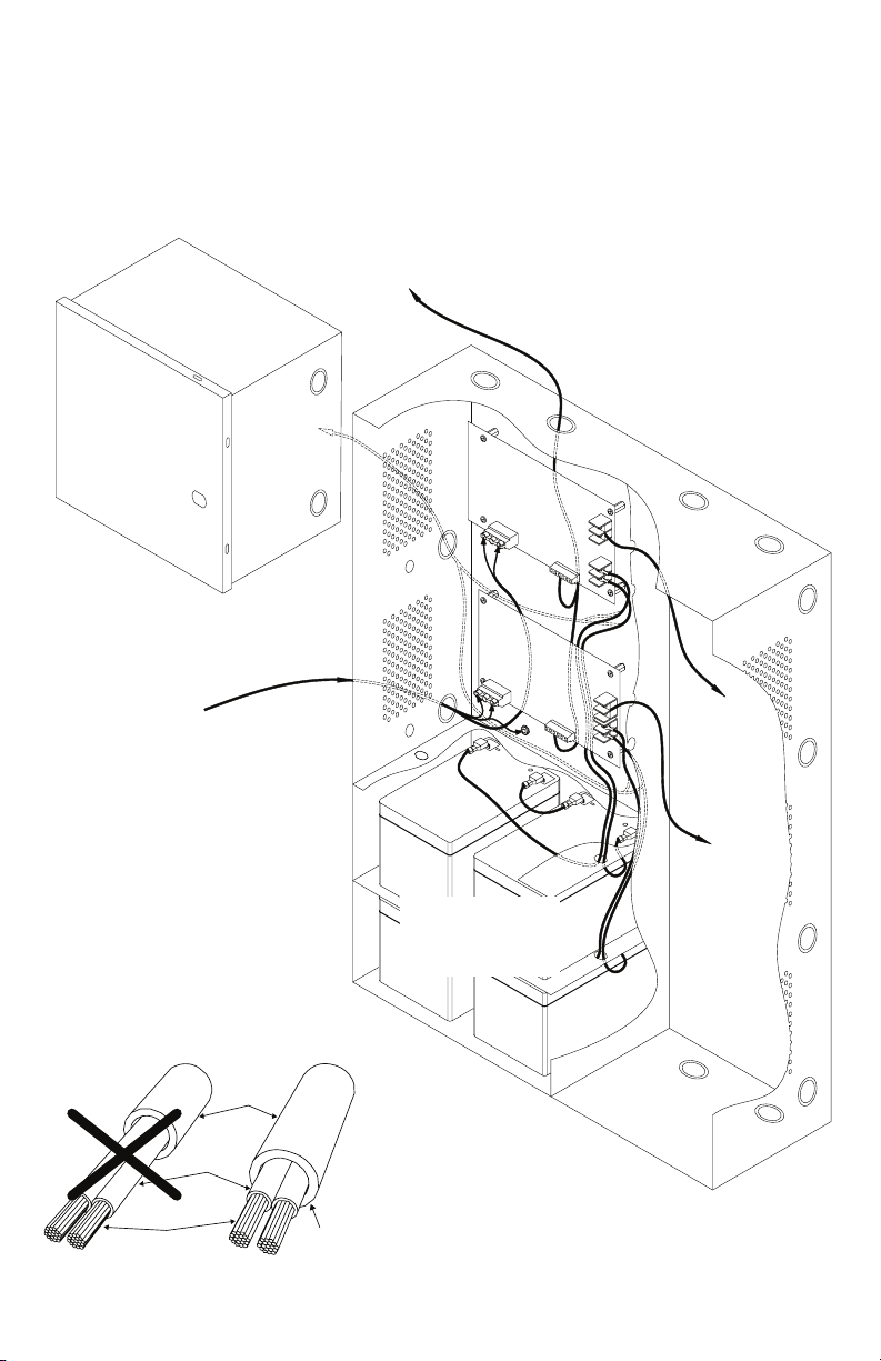
2. Connect unswitched AC power (220VAC, 50/60Hz) to the terminals marked [L, N] on both power supply
boards. Green branch wire connects to earth (safety) ground lug.
Use 14 AWG or larger for all power connections. (Fig. 2, pg. 6).
Keep power-limited wiring separate from non power-limited wiring.
Minimum 0.25” spacing must be provided.
CAUTION: Do not touch exposed metal parts.
Shut branch circuit power before installing or servicing equipment.
There are no user serviceable parts inside. Refer installation and servicing to qualified service personnel.
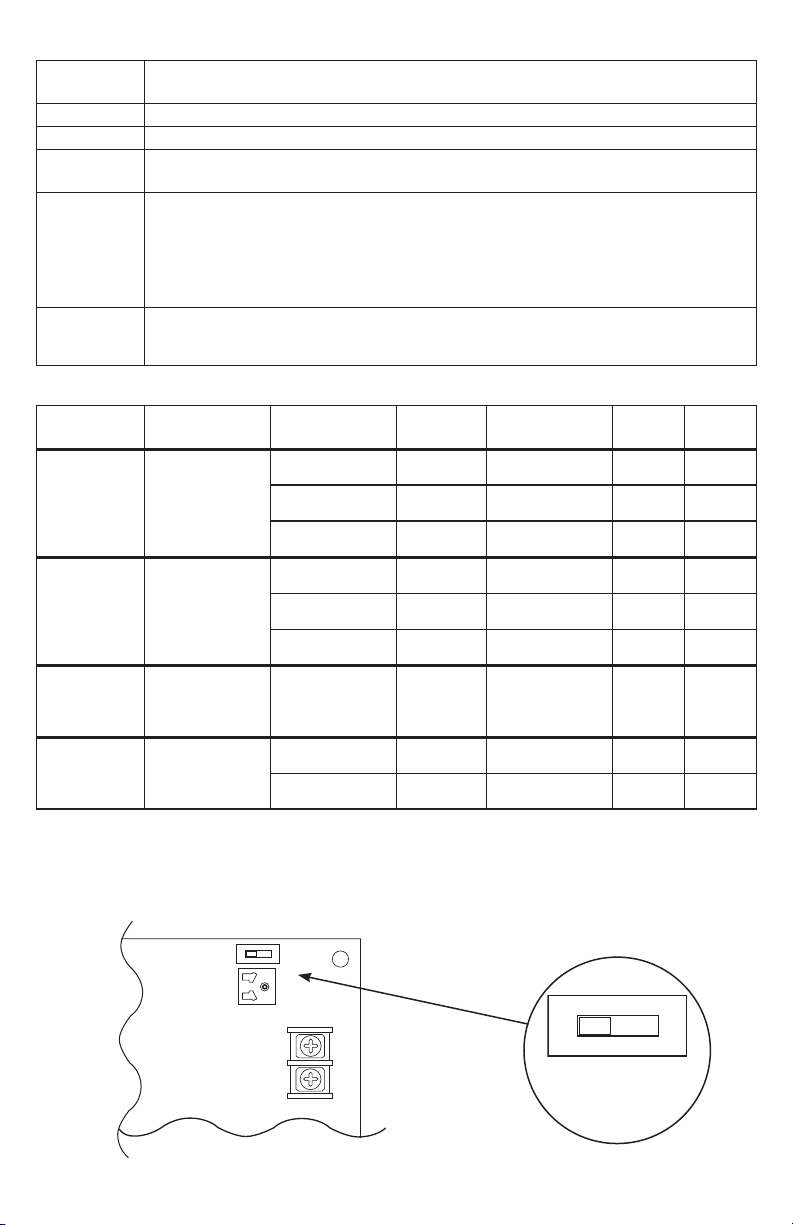
3. Select desired DC output voltage by setting SW1 to the appropriate position (Maximal11EV, Maximal13EV,
Maximal33EV, Maximal35EV and Maximal37EV) (Fig. 1, pg. 5).
Maximal55EV power supplies are factory set at 12VDC.
Maximal77EV power supplies are factory set at 24VDC.
Maximal75EV power supplies are factory set at 12VDC and 24VDC (Power Supply Board Stand-by Battery
Specifications, pg. 5).
4. Measure the output voltage of the unit before connecting any devices to ensure proper operation.
Improper or high voltage will damage these devices.
5. Connect devices to be powered to the terminals marked [+ DC –] (Fig. 2, pg. 6).
6. For Access Control applications batteries are optional. When batteries are not used, a loss of AC will result
in the loss of output voltage. When the use of stand-by batteries is desired, they must be lead acid or gel type.
Connect battery to the terminals marked [+ BAT –] (Figs. 2-7, pgs. 6-11).
Use two (2) 12VDC batteries connected in series for 24VDC operation (battery leads included).
7. Battery and AC Supervision outputs: It is required to connect supervisory trouble reporting devices to outputs
marked [AC FAIL, BAT FAIL] supervisory relay outputs marked [NC, C, NO] to appropriate visual
notification devices. Use 22 AWG to 18 AWG for AC Fail & Low/No Battery reporting (Fig. 2a, pg. 6).
8. Mount UL Listed tamper switch (not included) (Honeywell model 112 or equivalent) at the top of the
enclosure. Slide the tamper switch bracket onto the edge of the enclosure approximately 2” from the right
side (Fig. 2b, pg. 6). Connect tamper switch wiring to the Access Control Panel input or the appropriate UL
Listed reporting device. To activate alarm signal open the door of the enclosure.
9. Please ensure that the cover is secured with the provided key lock.
Maintenance:
Unit should be tested at least once a year for the proper operation as follows:
Output Voltage Test: Under normal load conditions the DC output voltage should be checked for proper
voltage level (Power Supply Stand-by Battery Specifications, pg. 5).
Battery Test: Under normal load conditions check that the battery is fully charged, check specified
voltage at the battery terminals and at the board terminals marked [+ BAT –] to ensure
that there is no break in the battery connection wires.
Note: AL400XB2V, AL600XB220 and AL1012XB220 (Power Supply Board) maximum charge current is 0.7A.
AL1024XB2V (Power Supply Board) maximum charge current is 3.6A.
Expected battery life is 5 years, however it is recommended to change batteries within 4 years or less if necessary.
Power Supply Board LED Diagnostics:
LED Power Supply Status
Red (DC) Green (AC)
ON
ON
Normal operating condition.
ON
OFF
Loss of AC. Stand-by battery supplying power.
OFF
ON
No DC output. Short circuit or thermal overload condition.
OFF
OFF
No DC output. Loss of AC. Discharged battery.
Red (Bat) Battery Status
ON Normal operating condition.
OFF Battery fail/low battery.

MaximalEV Expandable Power Systems - 5 -
Power Supply Board Terminal Identification:
Terminal
Legend Function/Description
L, G, N Connect 220VAC, 50/60Hz to these terminals: L to hot, N to neutral.
+ DC – Refer to MaximalEV Series Configuration Chart, pg. 3.
AC FAIL
NC, C, NO
Indicates loss of AC power. Relay normally energized when AC power is present.
Contact rating 1A @ 28VDC. AC or brownout fail is reported within 1 minute of event.
BAT FAIL
NC, C, NO
Indicates low battery condition, e.g. connect to alarm panel. Relay normally energized when
DC power is present. Contact rating 1A @ 28VDC. A removed battery is reported within 5
minutes. Battery reconnection is reported within 1 minute.
Low battery threshold:
12VDC output threshold set @ approximately 10.5VDC.
24VDC output threshold set @ approximately 21VDC.
+ BAT –
Stand-by battery connections.
AL400XB2V, AL600XB220 and AL1012XB220 (Power Supply Board) maximum charge
current is 0.7A. AL1024XB2V (Power Supply Board) maximum charge current is 3.6A.
Power Supply Board Stand-by Battery Specifications
Altronix
Model
Power Supply
Board Battery
20 min. of
Backup
4 hr. of
Backup
24 hr. of
Backup
60 hr. of
Backup
Maximal11EV
Maximal13EV
AL400XB2V
(Refer to Fig. 1a, 1b
on pg. 5 for Switch
[SW1] location
and position)
12VDC/40AH* N/A 4A 1A 300mA
24VDC/12AH N/A 200mA N/A N/A
24VDC/40AH* N/A 3A 1A 300mA
Maximal13EV
Maximal33EV
Maximal35EV
Maximal37EV
AL600XB220
(Refer to Fig. 1a, 1b
on pg. 5 for Switch
[SW1] location
and position)
12VDC/40AH* N/A 6A 1A 300mA
24VDC/12AH N/A 200mA N/A N/A
24VDC/40AH* N/A 6A 1A 300mA
Maximal35EV
Maximal55EV
Maximal75EV
AL1012XB220
(Factory set at
12VDC)
12VDC/12AH 10A
Battery capacity
for emergency
stand-by at least
20 mins.
N/A N/A
Maximal37EV
Maximal75EV
Maximal77EV
AL1024XB2V
(Factory set at
24VDC)
24VDC/12AH 8A 1.5A 200mA 100mA
24VDC/65AH* N/A 8A 1.5A 500mA
* Note: Additional battery enclosure required (Figs. 3-7, pgs, 7-11).
Power Supply Board Output Voltage Settings:
Fig. 1
+ DC ---
SW1
OFF - 24V
ON - 12V
ON
Fig. 1a - AL400XB2V / AL600XB220 Power Supply Board
Fig. 1b
ON
OFF - 24V
ON - 12V

- 6 - MaximalEV Expandable Power Systems
Tamper Switch
*12VDC operation: For 12VDC operation
only a single battery is needed.
Connect red battery lead
to terminal marked
[+ BAT] and to the
[positive (+)] terminal
of the battery. Connect
black battery lead to
terminal marked [BAT –]
and to the [negative (–)]
terminal of the battery.
–+
–+–+
12VDC
Rechargeable
Battery*
(Optional)
12VDC
Rechargeable
Battery*
(Optional)
12VDC
Rechargeable
Battery*
(Optional)
Line Neutral
Line Neutral
Input 220VAC, 50/60Hz
Ground Lug
BAT FAIL
L G N
+ DC --
NO C NC NO C NC
+ BAT --
AC FAIL
BAT FAIL
Power Supply Board
Power Supply Board
L G N
+ DC --
NO C NC NO C NC
+ BAT --
AC FAIL
-- DC +-- BAT +
Fig. 2
Fig. 2b
Edge of
Enclosure
to Access Control Panel
or U.L. Listed
Reporting Device
Enclosure
Honeywell
Model 112
Tamper Switch
or equivalent
(Not Included)
Power Supply Board
[DC] Terminal Layout for
AL1012XB220
Power Supply Board
[BAT] Terminal Layout for
AL1024XB2V
Fig. 2a

MaximalEV Expandable Power Systems - 7 -
NEC Power-Limited Wiring Requirements for Maximal11EV:
Power-limited and non power-limited circuit wiring must remain separated in the cabinet. All power-limited
circuit wiring must remain at least 0.25” away from any non power-limited circuit wiring. Furthermore, all
power-limited circuit wiring and non power-limited circuit wiring must enter and exit the cabinet through differ-
ent conduits. One such example of this is shown below. Your specific application may require different conduit
knockouts to be used. Any conduit knockouts may be used. For power-limited applications, use of conduit is
optional. All field wiring connections must be made employing suitable gauge CM or FPL jacketed wire (or
equivalent substitute).
Note: Refer to wire handling drawing below for the proper way to install the CM or FPL jacketed wire (Fig. 3a).
External
Jacketed
Shield
Incorrect Wire
Handling
Correct Wire
Handling
Pull back
external jacketed
shield approx. 1/2”.
Wire
Insulation
Solid Copper
Conductors
Fig. 3
Fig. 3a
Supervisory Connections
(power-limited)
Input
220VAC 50/60Hz
(non power-limited)
Optional Battery
Enclosure
(non power-limited)
DC Output
Wiring
Battery
Connections
(non power-limited)

- 8 - MaximalEV Expandable Power Systems
NEC Power-Limited Wiring Requirements for Maximal13EV:
Power-limited and non power-limited circuit wiring must remain separated in the cabinet. All power-limited
circuit wiring must remain at least 0.25” away from any non power-limited circuit wiring. Furthermore, all
power-limited circuit wiring and non power-limited circuit wiring must enter and exit the cabinet through differ-
ent conduits. One such example of this is shown below. Your specific application may require different conduit
knockouts to be used. Any conduit knockouts may be used. For power-limited applications, use of conduit is
optional. All field wiring connections must be made employing suitable gauge CM or FPL jacketed wire (or
equivalent substitute).
Note: Refer to wire handling drawing below for the proper way to install the CM or FPL jacketed wire (Fig. 4a).
External
Jacketed
Shield
Incorrect Wire
Handling
Correct Wire
Handling
Pull back
external jacketed
shield approx. 1/2”.
Wire
Insulation
Solid Copper
Conductors
Fig. 4
Fig. 4a
Supervisory Connections
(power-limited)
Input
220VAC 50/60Hz
(non power-limited)
Optional Battery
Enclosure
(non power-limited)
DC
Output
Wiring
Battery
Connections
(non power-limited)

MaximalEV Expandable Power Systems - 9 -
NEC Power-Limited Wiring Requirements for
Maximal33EV, Maximal35EV, and Maximal55EV:
Power-limited and non power-limited circuit wiring must remain separated in the cabinet. All power-limited
circuit wiring must remain at least 0.25” away from any non power-limited circuit wiring. Furthermore, all
power-limited circuit wiring and non power-limited circuit wiring must enter and exit the cabinet through differ-
ent conduits. One such example of this is shown below. Your specific application may require different conduit
knockouts to be used. Any conduit knockouts may be used. For power-limited applications use of conduit is
optional. All field wiring connections must be made employing suitable gauge CM or FPL jacketed wire (or
equivalent substitute).
Note: Refer to wire handling drawing below for the proper way to install the CM or FPL jacketed wire (Fig. 5a).
External
Jacketed
Shield
Incorrect Wire
Handling
Correct Wire
Handling
Pull back
external jacketed
shield approx. 1/2”.
Wire
Insulation
Solid Copper
Conductors
Fig. 5
Fig. 5a
Input
220VAC 50/60Hz
(non power-limited)
Optional Battery
Enclosure
(non power-limited)
DC
Output
Wiring
Battery
Connections
(non power-limited)
Supervisory Connections
(power-limited)

- 10 - MaximalEV Expandable Power Systems
NEC Power-Limited Wiring Requirements for
Maximal37EV and Maximal75EV:
Power-limited and non power-limited circuit wiring must remain separated in the cabinet. All power-limited
circuit wiring must remain at least 0.25” away from any non power-limited circuit wiring. Furthermore, all
power-limited circuit wiring and non power-limited circuit wiring must enter and exit the cabinet through differ-
ent conduits. One such example of this is shown below. Your specific application may require different conduit
knockouts to be used. Any conduit knockouts may be used. For power-limited applications use of conduit is
optional. All field wiring connections must be made employing suitable gauge CM or FPL jacketed wire (or
equivalent substitute).
Note: Refer to wire handling drawing below for the proper way to install the CM or FPL jacketed wire (Fig. 6a).
External
Jacketed
Shield
Incorrect Wire
Handling
Correct Wire
Handling
Pull back
external jacketed
shield approx. 1/2”.
Wire
Insulation
Solid Copper
Conductors
Fig. 6
Fig. 6a
Supervisory Connections
(power-limited)
Input
220VAC 50/60Hz
(non power-limited)
Optional Battery
Enclosure
(non power-limited)
DC Output
Wiring
Battery
Connections
(non power-limited)

MaximalEV Expandable Power Systems - 11 -
NEC Power-Limited Wiring Requirements for Maximal77EV:
Power-limited and non power-limited circuit wiring must remain separated in the cabinet. All power-limited
circuit wiring must remain at least 0.25” away from any non power-limited circuit wiring. Furthermore, all
power-limited circuit wiring and non power-limited circuit wiring must enter and exit the cabinet through differ-
ent conduits. One such example of this is shown below. Your specific application may require different conduit
knockouts to be used. Any conduit knockouts may be used. For power-limited applications use of conduit is
optional. All field wiring connections must be made employing suitable gauge CM or FPL jacketed wire (or
equivalent substitute).
Note: Refer to wire handling drawing below for the proper way to install the CM or FPL jacketed wire (Fig. 7a).
External
Jacketed
Shield
Incorrect Wire
Handling
Correct Wire
Handling
Pull back
external jacketed
shield approx. 1/2”.
Wire
Insulation
Solid Copper
Conductors
Fig. 7
Fig. 7a
Supervisory Connections
(power-limited)
Input
220VAC 50/60Hz
(non power-limited)
Optional Battery
Enclosure
(non power-limited)
Battery
Connections
(non power-limited)
DC Output
Wiring

- 12 - MaximalEV Expandable Power Systems
Enclosure Dimensions (H x W x D approximate):
26” x 19” x 6.25” (660.4mm x 482.6mm x 158.8mm)
TOP
LEFT RIGHT
BOTTOM
1.25”
(31.75mm)
1.25”
(31.75mm)
1.25”
(31.75mm)
0.85”
(21.59mm)
0.85”
(21.59mm)
1”
(25.4mm)
0.85”
(21.59mm)
1”
(25.4mm)
0.85”
(21.59mm)
8.9”
(226.06mm)
19”
(482.6mm)
19”
(482.6mm)
19”
(
482.6mm
)
2”
(50.8mm)
2”
(50.8mm)
2”
(50.8mm)
6.25”
(158.75mm)
6.25”
(158.75mm)
4”
(101.6mm)
4”
(101.6mm)
2”
(50.8mm)
4”
(101.6mm)
8.9”
(226.06mm)
8.4”
(213.36mm)
7”
(177.8mm)
7”
(177.8mm)
7”
(177.8mm)
8.4”
(213.36mm)
8.5”
(215.9mm)
8.5”
(215.9mm)
7.5”
(190.5mm)
10”
(254mm)
1.5”
(38.1mm)
1.5”
(38.1mm)
1.5”
(38.1mm)
26”
(660.4mm)
26”
(660.4mm)
7.5”
(190.5mm)
5”
(127mm)
26”
(660.4mm)
Altronix is not responsible for any typographical errors.
140 58th Street, Brooklyn, New York 11220 USA | phone: 718-567-8181 | fax: 718-567-9056
IIMaximalEV Series H02R MEMBER
This manual suits for next models
7
Table of contents
Popular Power Supply manuals by other brands

Lennox
Lennox G12 Series User information

Huawei
Huawei UPS2000 Series Development guide

Keithley
Keithley 2220-30-1 Declassification and security instructions

WAGO
WAGO Pro 2 manual

3Com
3Com Powerware Uninterruptible Power System Prestige... Installation and operator's manual

Altronix
Altronix R1224DC16CBV installation guide