- 2 - ALTV244220series
Overview:
ALTV244220 Series CCTV Power Supplies provide 24VAC or 28VAC distributed via four (4) fuse or PTC protected
outputs for powering CCTV cameras, heaters, and other video accessories.
Four (4) Output ALTV244220 Reference Chart:
Altronix
Model Number
Total
Output
Current
(A)
Output
Voltage
Number of
Outputs
PTC
Protected
Outputs
Fuse
Protected
Outputs
Output
Current
(max
per
output)
Line
Fuse
Ratings
Main
Fuse
Ratings
220VAC
50/60Hz
Input
Current
ALTV244220 4A 24VAC
4
----- P3.5A 1A/
250V
5A/
250V 0.5A
3.5A 28VAC
ALTV244CB220 4A 24VAC P----- 2.5A
3.5A 28VAC
ALTV244175220 7.25A 24VAC ----- P3.5A
-----
10A/
250V 0.8A
6.25A 28VAC
ALTV244175CB220 7.25A 24VAC P----- 2.5A
6.25A 28VAC
ALTV244300220 14A 24VAC ----- P3.5A 15A/
32V 1.8A
12A 28VAC
ALTV244300CB220 10A 24VAC P----- 2.5A
10A 28VAC
Specifications:
Installation Instructions:
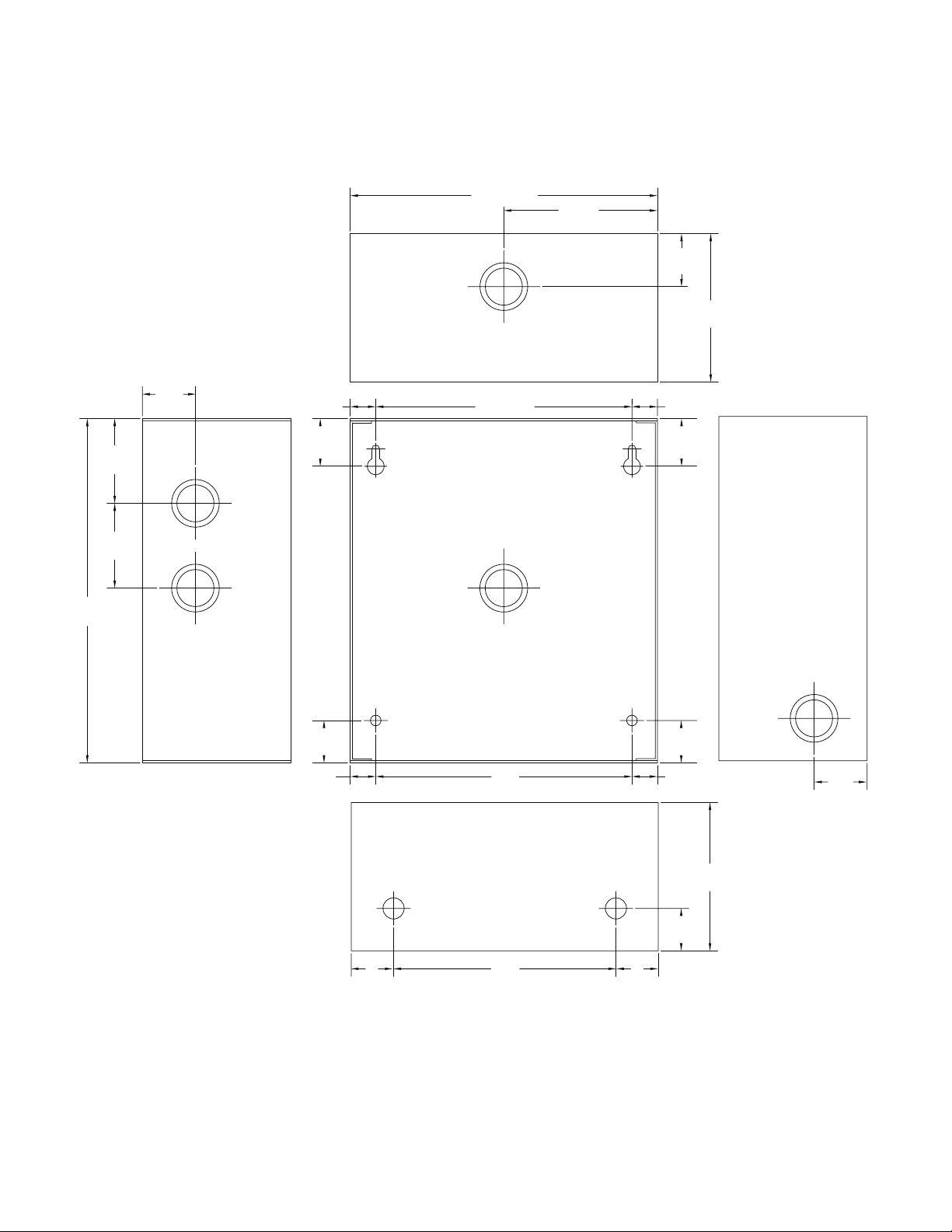
1. Mount unit in the desired location. Mark and predrill holes in the wall to line up with the top two keyholes in the
enclosure. Install two upper fasteners and screws in the wall with the screw heads protruding. Place the enclosure’s
upper keyholes over the two upper screws, level and secure. Mark the position of the lower two holes. Remove the
enclosure. Drill the lower holes and install the three fasteners. Place the enclosure’s upper keyholes over the two
upper screws. Install the two lower screws and make sure to tighten all screws (Enclosure Dimensions, pg. 6-7).
Secure enclosure to earth ground.
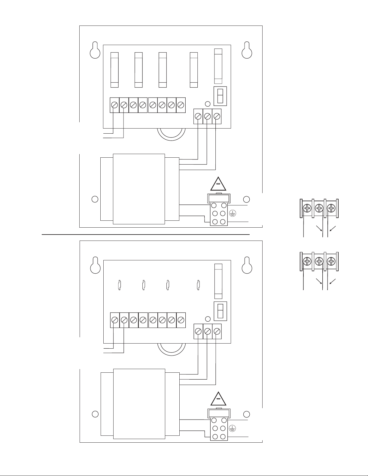
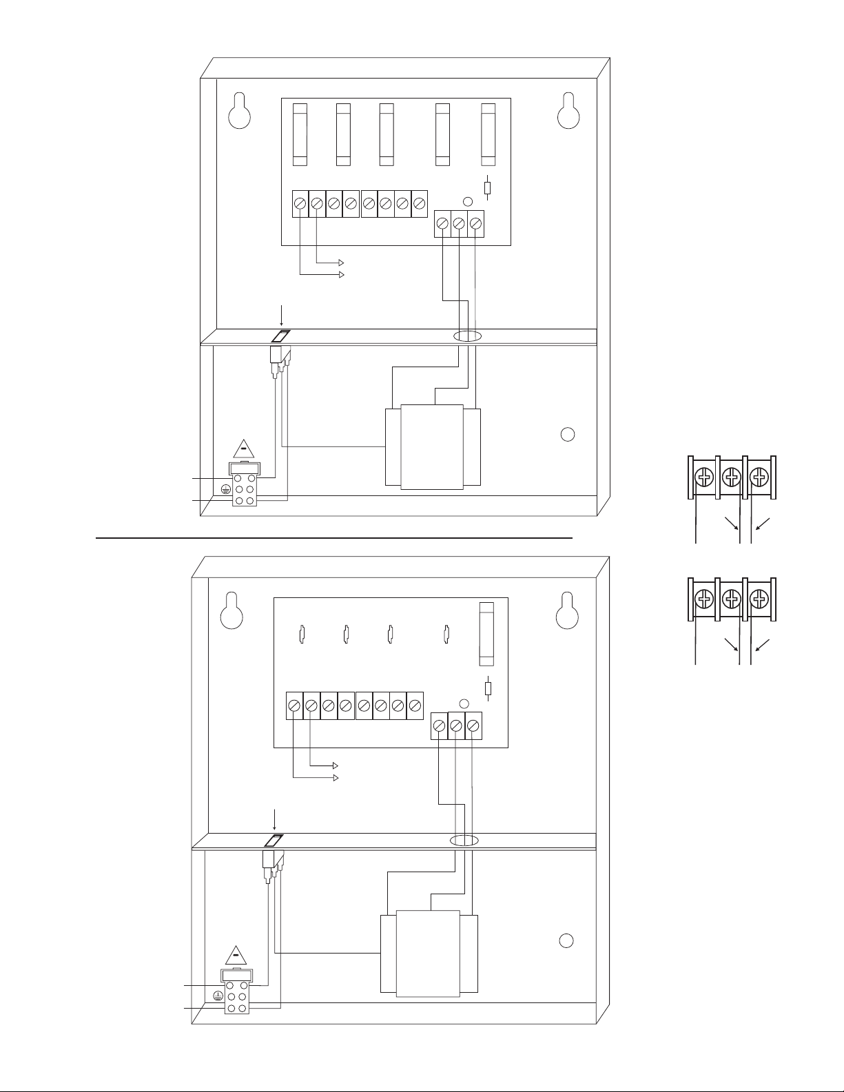
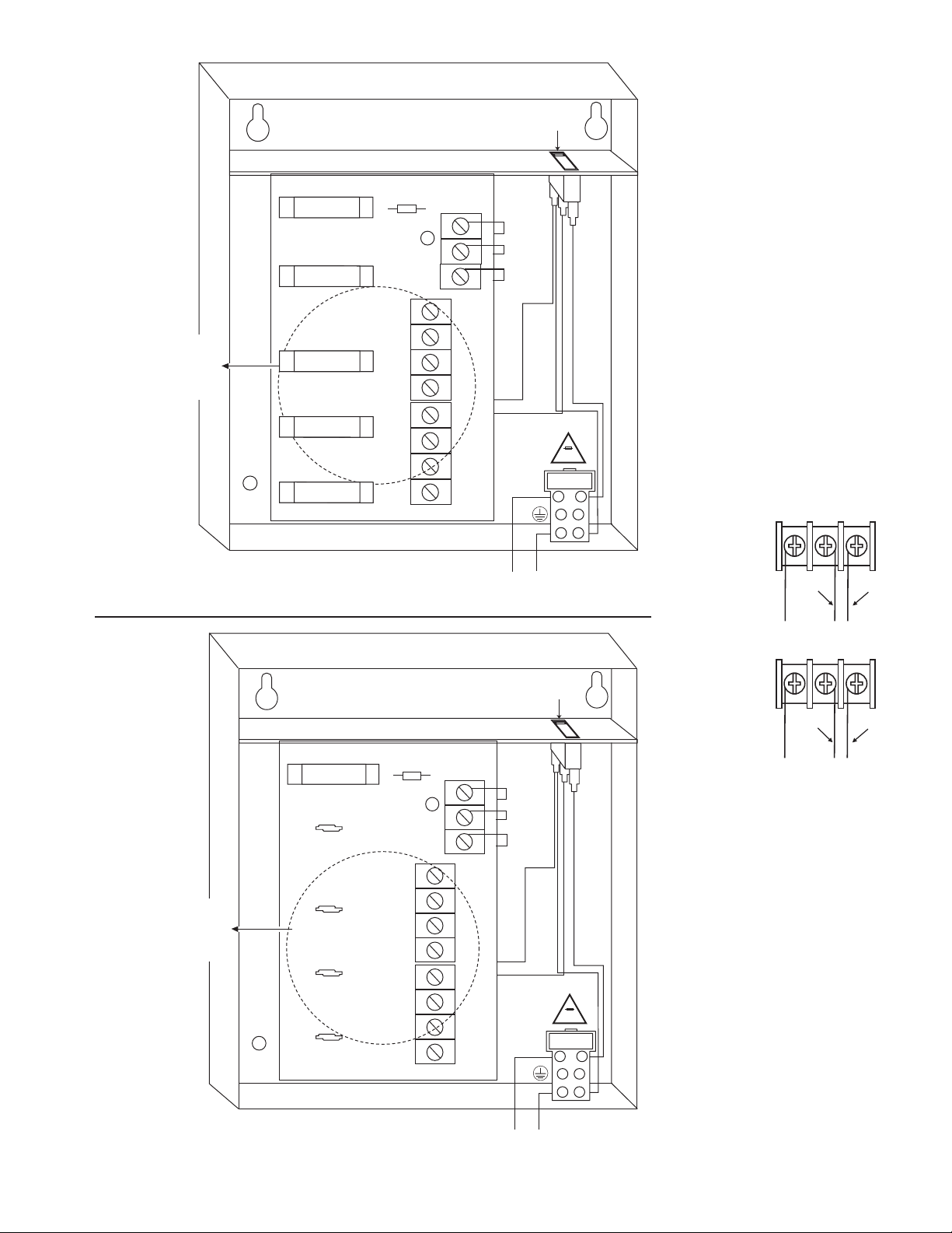
2. Set main switch to the OFF position (Fig. 1-6, pgs. 4-6).
3. All units are factory set for 24VAC operation.
For 28VAC operation adjust unit prior to mounting and applying power as follows: change the wire position so that
the black wire [28V] is connected to the terminal marked [P] and the yellow wire [24V] is connected to the terminal
marked [S].
4. Connect unswitched AC circuit (220VAC, 50/60Hz) as follows: Green branch wire (ground) connects to the terminal
marked , Line connects to the terminal marked [L], and Neutral connects to the terminal marked [N] of the Inlet
Appliance Connector. (Figs. 1-6, pgs. 4-6).
5. Set main switch to the ON position (Fig. 1-6, pgs. 4-6).
6. Measure output voltage before connecting devices. This helps avoiding potential damage.
CAUTION: Determine the maximum operating voltage of the equipment being powered before
adjusting the output voltage.
Agency Listing:
• CE Approved.
Input:
• 220VAC, 50/60Hz.
Output:
• Four (4) fuse protected outputs.
• 24VAC or 28VAC supply current.
• Outputs are rated @ 3.5A (fused) or 2.5A (PTC).
• Surge suppression.
Features:
• Slow blow main fuse on power distribution board.
• AC power LED.
• Power ON/OFF switch.
• Spare fuses provided.
(all models w/primary and/or secondary fuses).
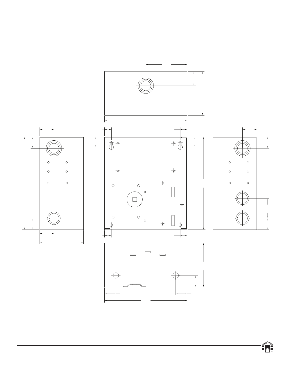
Enclosure Dimensions (H x W x D approx.):
ALTV244220 and ALTV244CB220:
8.5” x 7.5” x 3.5” (215.9mm x 190.5mm x 88.9mm).
ALTV244175220, ALTV244175CB220,
ALTV244300220 and ALTV244300CB220:
8.5” x 7.5” x 3.75” (215.9mm x 191mm x 95mm).
ON
INPUT
OFF
1P 1N 2P 2N 3P 3N 4P 4N
LED
SW1
MAIN FUSE
NPS
F1 F2 F3 F4
XFMR
24VAC or 28VAC fused output 1
(Follow same procedure
using terminals 2P & 2N
through 4P & 4N fused
outputs 2 through 4)
220VAC input
50/60 Hz,
0.5A
1A
250V