www.errebispa.com 9
ITALIANO
•
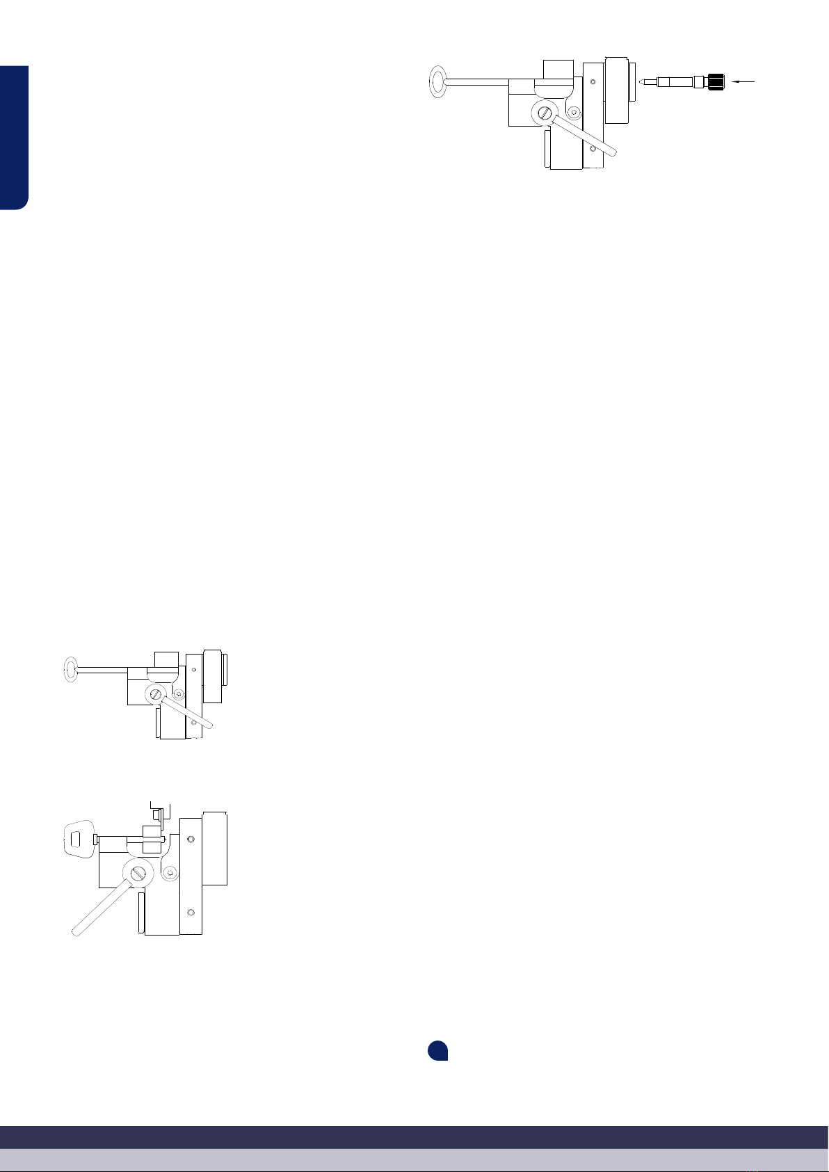
• Agganciare la chiave vergine e la chiave da cifrare nelle corrispondenti
ganasce utilizzando le leve “S”.
• La mappa della chiave deve toccare contro la parte inferiore della ga-
nascia.
• La mappa della chiave deve appoggiare contro la parete verticale della
ganascia.
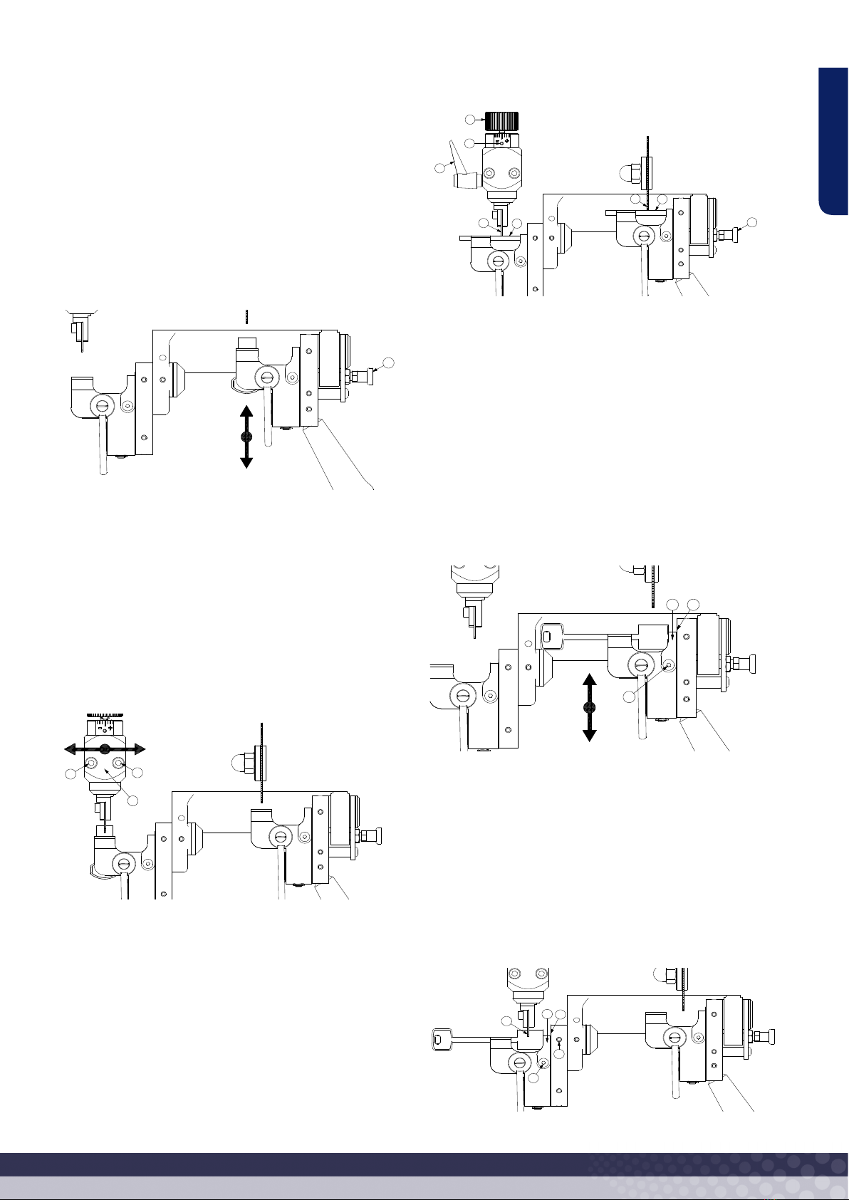
• Mettere in funzione la rotazione della fresa azionando il corrispondente
interruttore.
• Con la leva “W” nella posizione più alta, avvicinare le chiavi alla fresa
“C” e al tastatore “T”.
• Inserire il tastatore nel solco della chiave da duplicare.
• Spostare delicatamente la leva “W” verso il basso. Si raccomanda di
lavorare realizzando delle pause, senza forzare la fresa.
• Ripetere questa stessa operazione per tutte le volte necessarie, no a
completare la cifratura dei tagli verticali della chiave.
• Qualora durante la cifratura si producessero delle sbavature sulla chia-
ve duplicata, eliminarle utilizzando la spazzola.
MANUTENZIONE
Per l’esecuzione di qualsiasi operazione di manutenzione, è necessario ris-
pettare le seguenti norme:
• Non realizzare mai alcuna operazione con la macchina accesa.
• Il cavo di alimentazione va scollegato dalla presa elettrica.
• Bisogna seguire rigorosamente le indicazioni date nel presente ma-
nuale.
• Utilizzare pezzi di ricambio originali.
•
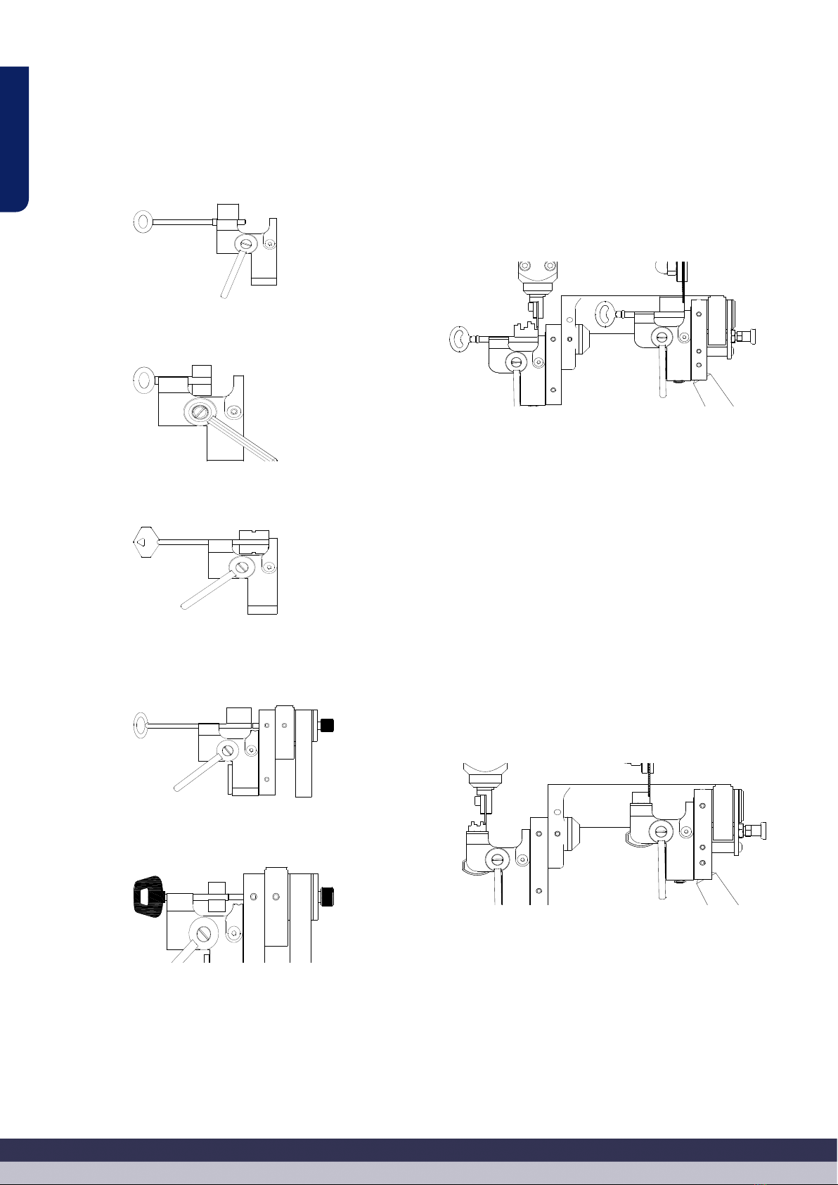
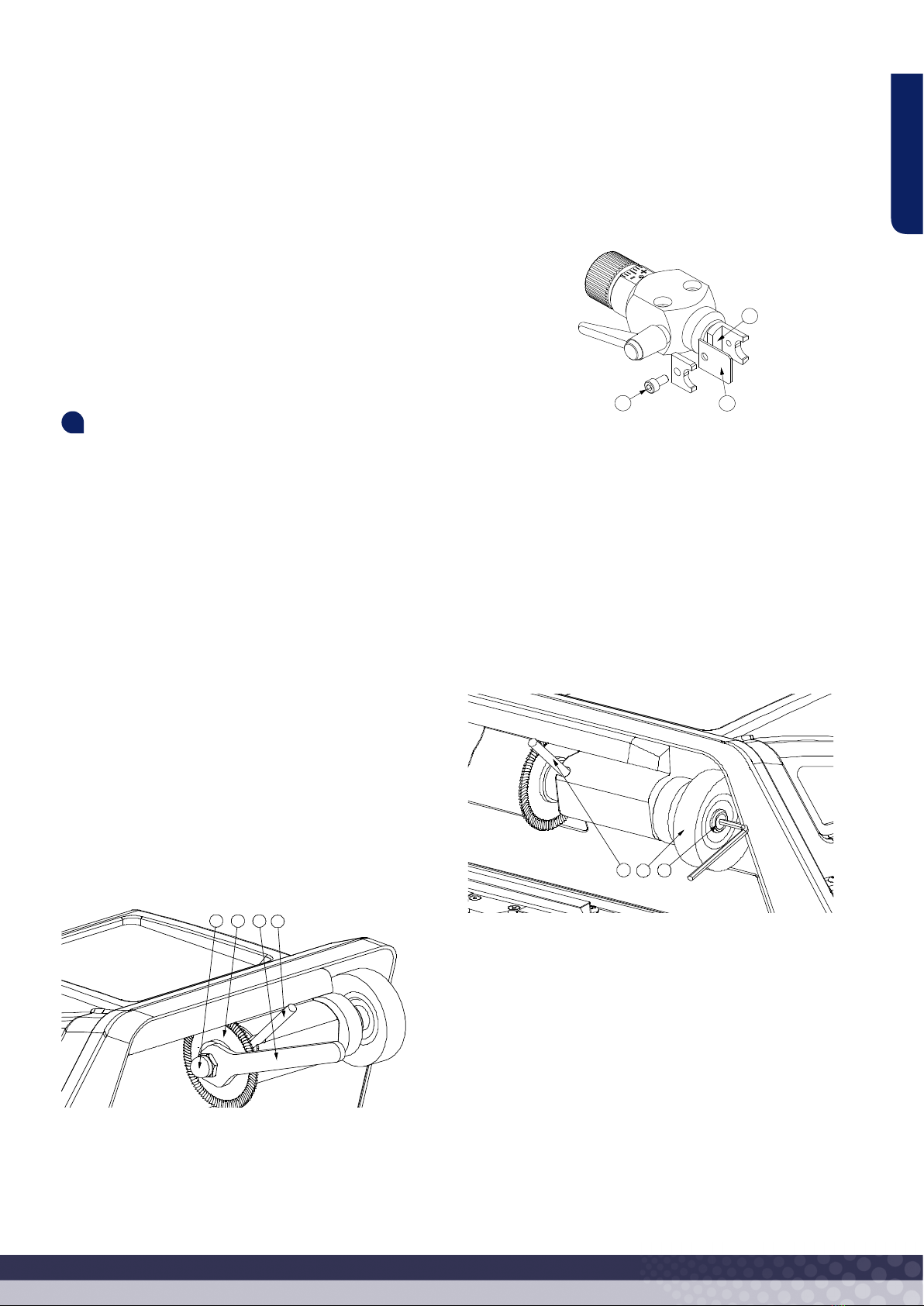
4.1 SOSTITUZIONE DELLA FRESA
Per sostituire la fresa, procedere come segue:
• Spegnere e scollegare la macchina.
• Inserire lo spillo “A”, fornito con gli accessori, nel foro che blocca la ro-
tazione della testata. Per trovare il foro, girare manualmente la testata.
• Con la chiave ssa “B”, egualmente fornita con gli accessori, allentare
il dado “E”. Tenere in considerazione che il dado “E” è provvisto di le-
ttatura sinistra.
• Estrarre la fresa “C” usurata.
• Installare la nuova fresa “C” e serrarla serrando il dado “E”. Accertarsi
che la fresa resti montata con i denti di taglio rivolti verso la posizione
corretta. Tenere in considerazione che la fresa gira in senso orario.
• Estrarre lo spillo “A”.
• Dopo la sostituzione della fresa, si raccomanda di realizzare la “Rego-
lazione di profondità di taglio”. La procedura è indicata nel punto 3.1.2
del presente manuale.
4.2 SOSTITUZIONE DEL TASTATORE
Per sostituire il tastatore, procedere come segue:
• Spegnere e scollegare la macchina.
• Allentare la vite “F” utilizzando la chiave a brugola nº4 fornita con gli
accessori.
• Estrarre il tastatore “T” usurato.
• Installare il nuovo tastatore “T”. Accertandosi che la parte posteriore del
tastatore appoggi contro il supporto “G”, serrare la vite “F”.
• Dopo la sostituzione del tastatore, si raccomanda di realizzare la “Re-
golazione di profondità di taglio”. La procedura è indicata nel punto
3.1.2 del presente manuale.
4.3 SOSTITUZIONE DELLA SPAZZOLA
Per sostituire la spazzola, procedere come segue:
• Spegnere e scollegare la macchina.
• Inserire lo spillo “A”, fornito con gli accessori, nel foro che blocca la ro-
tazione della testata. Per trovare il foro, girare manualmente la testata.
• Allentare la vite “H” utilizzando la chiave a brugola nº4 fornita con gli
accessori.
• Estrarre la spazzola “J” usurata.
• Installare la nuova spazzola “J” e ssarla serrando la vite “H”. Non se-
rrarla con eccessiva forza; in tal modo quando si renderà nuovamente
necessario sostituire la spazzola “H”, sarà più facile smontarla.
• Estrarre lo spillo “A”.
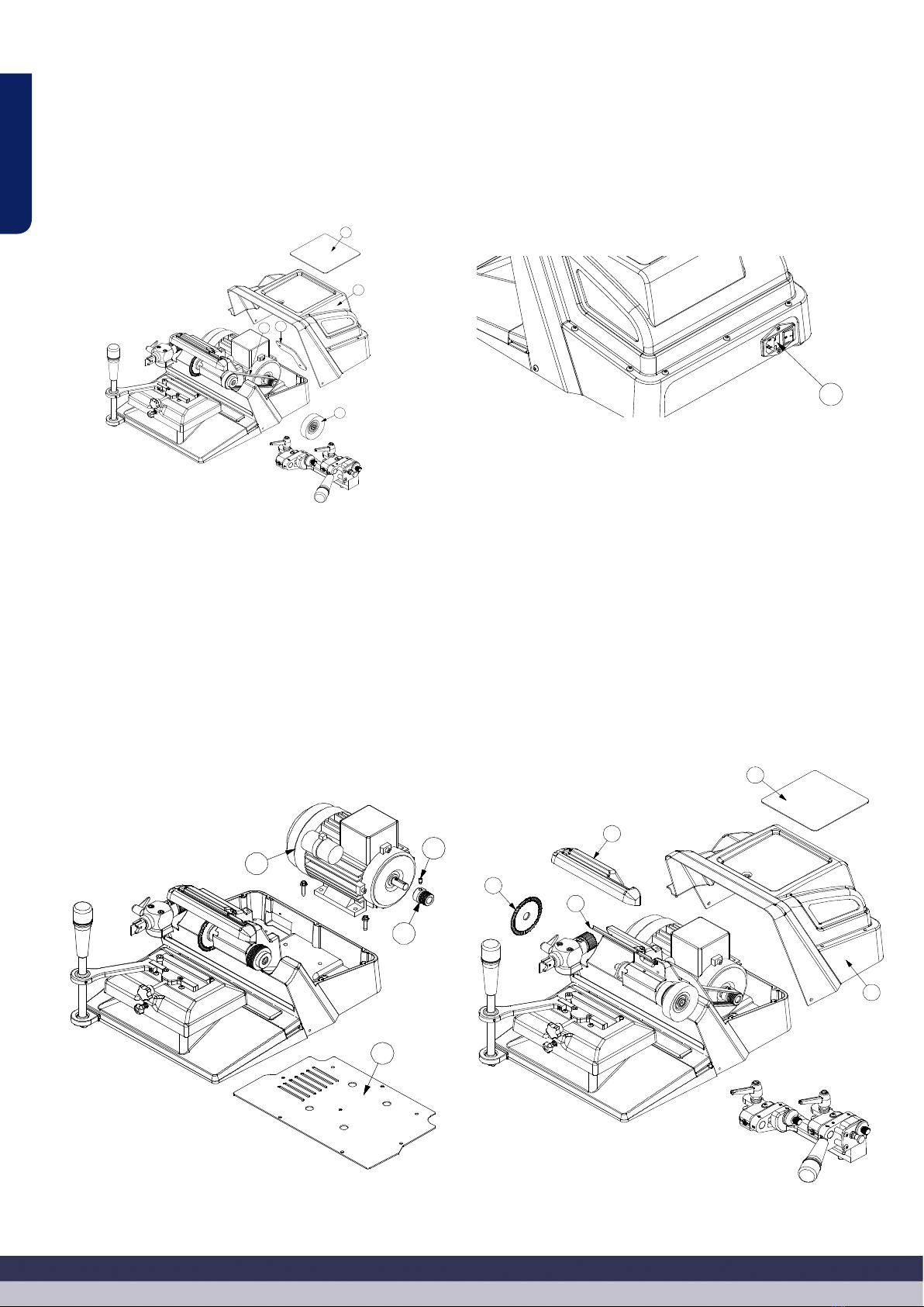
4.4 SOSTITUZIONE DELLA CINGHIA
La cinghia della macchina DELTA ADVANCE è elastica, pertanto non è ne-
cessaria l’esecuzione di operazioni di tenditura.
Qualora si renda necessaria la sostituzione della cinghia, procedere come
segue:
• Spegnere e scollegare la macchina.
• Estrarre il carrello dalla macchina (BIT o TAGLI VERTICALI).
• Togliere il tappetino “K” della parte superiore.
• Togliere il coperchio “N” che occulta il motore. Per farlo, togliere le 11
viti che lo ssano al basamento.
• Togliere la lamiera “O”. Per farlo, svitare le 2 viti.
• Togliere la spazzola “J”. La procedura è indicata nel punto 4.3 del pre-
sente manuale.
• Togliere la cinghia vecchia “I”. Per estrarla dalle pulegge, girare ma-