5
We reserve the right to any technical change.
Valid on 2022.05.23
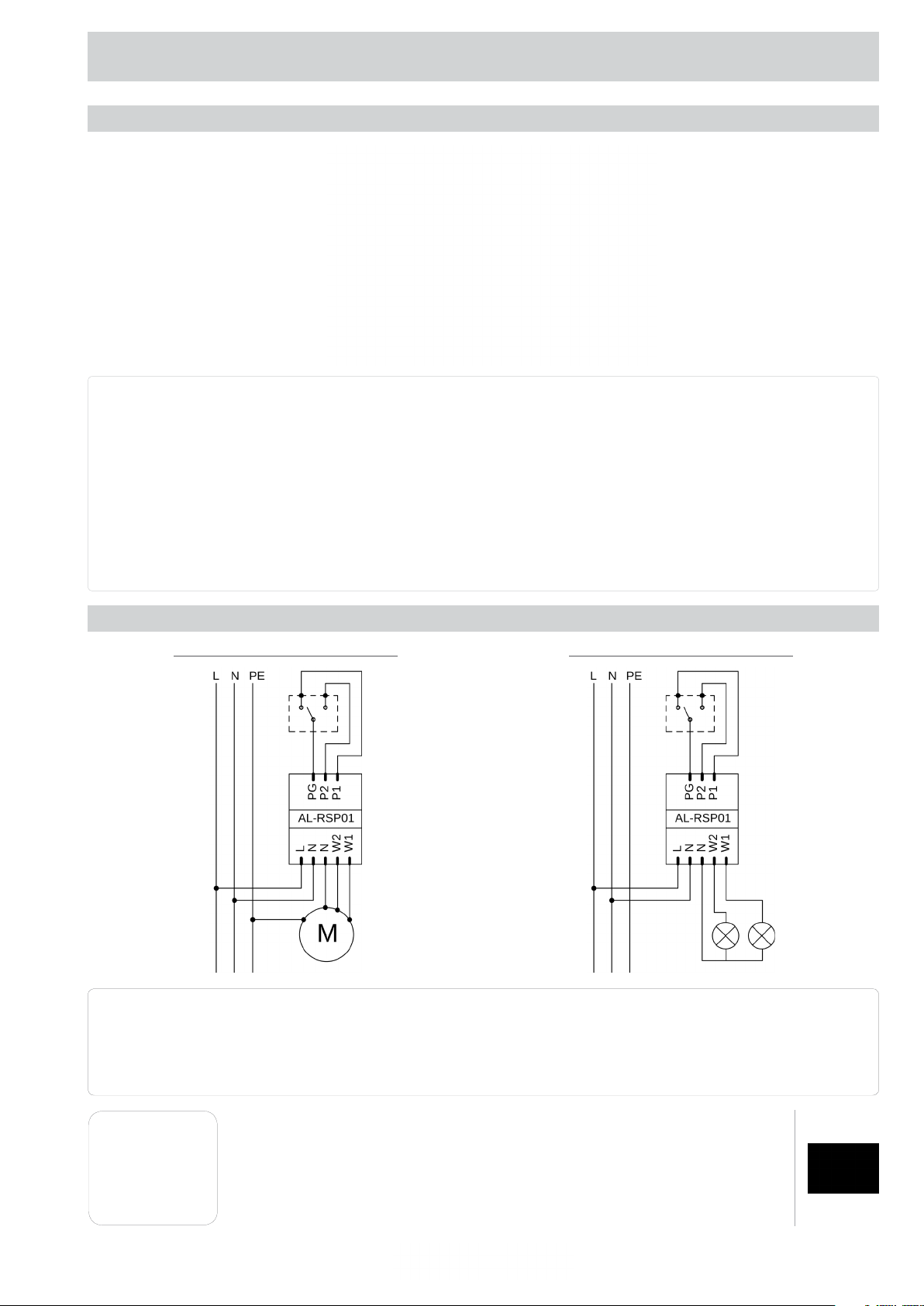
PROGRAMMING MANUAL FOR UNDERPLASTER RADIO CONTROLLER AL-RSP 01
6.1. PROGRAMMING OF THE FIRST TRANSMITTER
Turn on the power, which will be
confirmed by a short voltage
The transmitter has been added.Press“UP” button , which
will be confirmed by a short
supply to the W1 or W2
In the interval of two seconds
In the interval of two seconds
press the button
press the button
6. MODE OF LIGHTNING CONTROL OPERATION
I
While the power supply is ON press
3x the PROG programming
The transmitter has been added.
button , which will be confirmed by
II
While the power supply is
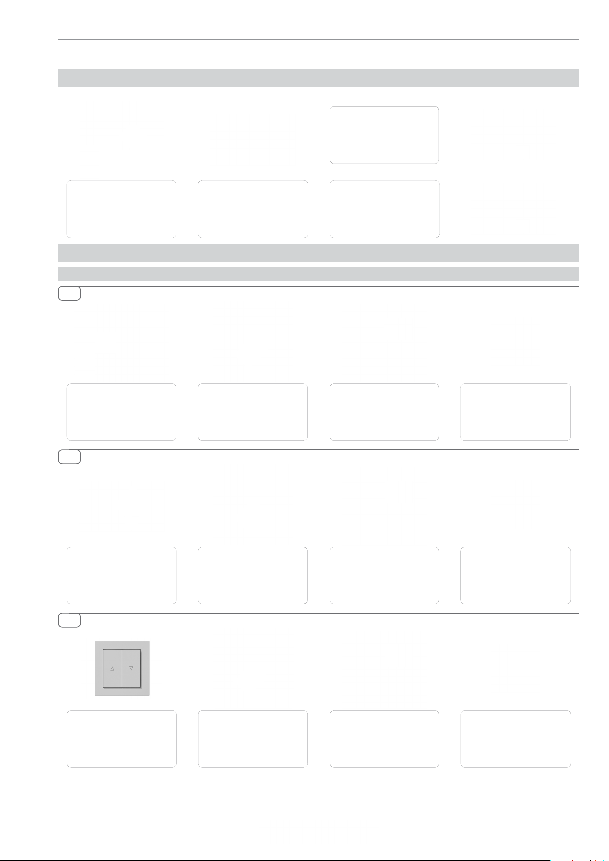
ON quickly press 3x “UP” or “DOWN”
The transmitter has been added.
button on the switch, which will
III
With the programming button
By turning on power supply
With a switch
“P2” (1xP2 for W1, 2xP2 for W2),
“P2” (1xP2 for W1, 2xP2 for W2),
which will be confirmed by
which will be confirmed by
voltage supply to the
the LED.
be confirmed by a short voltage
supply to the W1 or W2
applying brief voltage pulses
applying brief voltage pulses
to the output W1 or W2
to the output W1 or W2
W1 or W2 output.
Press“UP” button , which
will be confirmed by a short
voltage supply to the
W1 or W2 output.
output.
Press“UP” button , which
will be confirmed by a short
In the interval of two seconds
press the button
“P2” (1xP2 for W1, 2xP2 for W2),
which will be confirmed by
voltage supply to the
applying brief voltage pulses
to the output W1 or W2
W1 or W2 output.
6.2. ADDING ANOTHER TRANSMITTER
Press“P2” button twice of the already
programmed transmitter, which
The transmitter has been added.
will be confirmed by a short
Press the“P2” button of
the new transmitter,
which will be confirmed
by a short voltage supply to thevoltage supply to the W1 or W2
output. W1 or W2 output.
output.