OPERATIONAL MANUAL. ELECTROHYDRAULIC LEVELLER WITH SWING LIP SL SERIES88
DESCRIPTION AND WORK
The main components of the leveller are:
• Back support (frame). Designed for mounting the back part of the leveller to the pit;
• Lift part. Compensate for the difference in height of the truck body and the loading ramp;
• lip. Designed for overlapping and resting on the vehicle body;
• Support beam. Required for mounting the front part of the leveller to the pit. It is a
support element for fastening the hydraulic cylinders;
• Protective shutters. Used for closing of the gap between leveller and pit when the leveller
is in the raised position. Provides protection from crushing or entrapment oflimbs;
• Service support. Used to lock the rotary motion of the leveller during maintenance or
service work;
• Hydraulic unit. It provides hydraulic oil into the cylinders, thereby lifting the rotary part
of the leveller;
• Hydraulic cylinders. They are used for raising and lowering the rotary part of the leveller;
• Lip cylinder. It provides turning and folding of the lip.
2.4 DESIGN AND WORK
YATTENTION! During leveller positioning on to the body of the truck, you should make sure
that people or other objects are not within the working area of leveller. Only qualied workers
can manage the leveller. You should monitor carefully the movement of leveller during the
operation. Everyone who works with the leveller should be acquainted with its functions. The
operator must carefully read the operational manual.
During lifting of the loading/unloading platform by pressing the button for raising of the leveller,
the main power switch button must be turned on the‘1’position. Otherwise, the leveller will not
follow the height dierence of the truck body, and lead to machinery breakdown.
2.4.1 INTERFACING WITH VEHICLE
For safety reasons it is recommended to ensure the following things:
• there are no people or foreign objects at the entrance between the vehicle and the leveller;
• when you are driving up the drop side (tail lift) of the vehicle must be lowered;
• after parking, the vehicle (trailer) is fixed in place and cannot roll back or drive off
(the ignition key switched off, hand brake applied and wheel wedges installed).
2.4.2 LEVELLER POSITIONING IN THE VEHICLE BODY
YATTENTION! If leveller lip is equipped with additional unfolding segmentation, for narrower width
vehicles, the segments will be folded automatically. After the unsetting action of the leveller side
segments, they will return to the operating state. During the next operational cycle the central part
and the side segments will be rotated together, allowing use of the entire width of the lip.
To install the leveller in the vehicle body:
• turn the main switch to position ‘1’. During the leveller operation, loading or unloading
works it is prohibited to change the switch position;
• press the lip lift button. Hold it until the rotating part rises to the highest position and
the lip forms a single plane with the rotating part of the leveller;
• release the lift button. After this the rotating part begins to drop, and the lip lies on the
loading surface of the vehicle body;
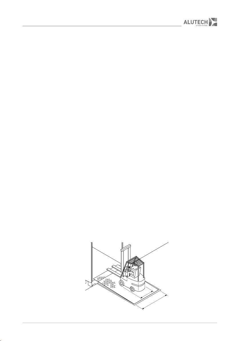
• make sure the lip finally lies on the vehicle body surface and comes into it 80–100 mm
across its full-width.