TARGO DRIVES (TR SERIES) |ANTRIEBE TARGO (SERIE TR) |COMMANDES TARGO (SÉRIE TR)2
GENERAL WARNINGS AND SAFETY RULES
1. GENERAL WARNINGS AND SAFETY RULES
YThis manual contains important information concerning safety. Prior to commencing
installation study closely all the information provided below. Save this manual for future
reference!
Follow the precautions, provided by any active regulatory documents and by those in this
manual. Please, ensure compliance with the requirements of standards concerning the con-
struction, mounting and operation of automated doors (EN 12604, EN 12453), as well as other
possible local rules and regulations.
Mounting, programming, conguration and operation of the product in violation of the require-
ments are prohibited, as this can result in damages, injuries and cause losses.
Mounting, connections, nal tests, commissioning and maintenance should be performed only
by qualied specialists.
Making any changes to any elements of the product structure and unintended use of the product
are prohibited. The manufacturer is not liable for any damages, caused by unauthorised changes
in the product or its unintended use.
The product is not intended for use in acid, salt or explosion hazard environments.
When performing any works (mounting, repair, maintenance, cleaning, etc.) and connections
inside the drive, disconnect the mains circuit. If the master switch or similar device is out of
sight, then attach a safety sign stating:‘Do not turn on. People are working’and take measures
preventing the possibility of accidental restoring of the power supply.
The company reserves the right to introduce changes in this manual and the product construc-
tion without prior notication, but preserving the same functional capabilities and designation.
The content of this manual cannot be used as the basis for legal claims.
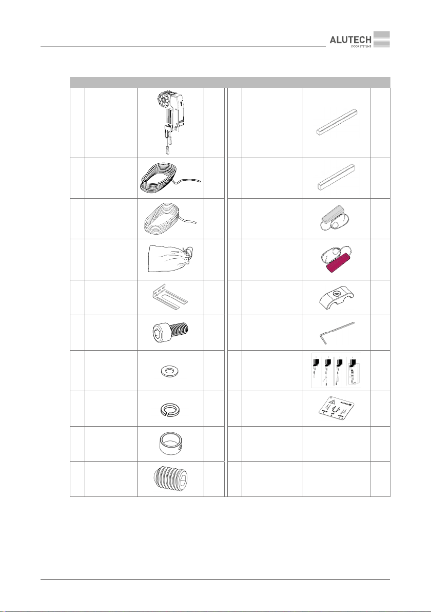
2. PRODUCT DESCRIPTION
(TR-3531-230E/TR-5020-230E/TR-5024-230E/TR-5013-400E/TR-5020-400E/TR-5024-400E/
TR-10024-400E/TR-13018-400E/TR-13012-400E) electromechanical shaft-type drives are de-
signed for the automation of balanced sectional industrial doors.
Applicable with external control unit:
• CU-TR230 for TR-3531-230E/TR-5020-230E/TR-5024-230E;
• CU-TR400 for TR-5013-400E/TR-5020-400E/TR-5024-400E/TR-10024-400E/TR-13018-400E/
TR-13012-400E.
The drive is equipped with an electric motor and a self-locking gear box. Control of the drive’s
nal stop positions is performed by the encoder.
In case of temporary loss of mains power and during repair and maintenance of the door;
emergency manual control is performed by unlocking the drive and using the chain operation
facility which will allow the door leaf to be operated manually.