AL42D/P
SELV
Istruzioni per l’uso - User guide
Alimentatore elettronico per LED, multicorrente-multitensione con PFC attivo. Idoneo per alimentare sia
strisce LED in tensione sia LED di potenza alimentati in corrente. La modalità di funzionamento è selezio-
nata attraverso il DIP SWITCH posto al disotto del coprimorsetto.
Regolazione della luminosità tramite funzione DALI, Push, interfaccia 1-10V o 0-10V idonea per lavorare
sia con potenziometri resistivi che sistemi attivi come Gateway, Interfacce Konnex, Touch Screen, ecc.
Funzione Master/Slave con cavi standard.
MADE IN ITALY
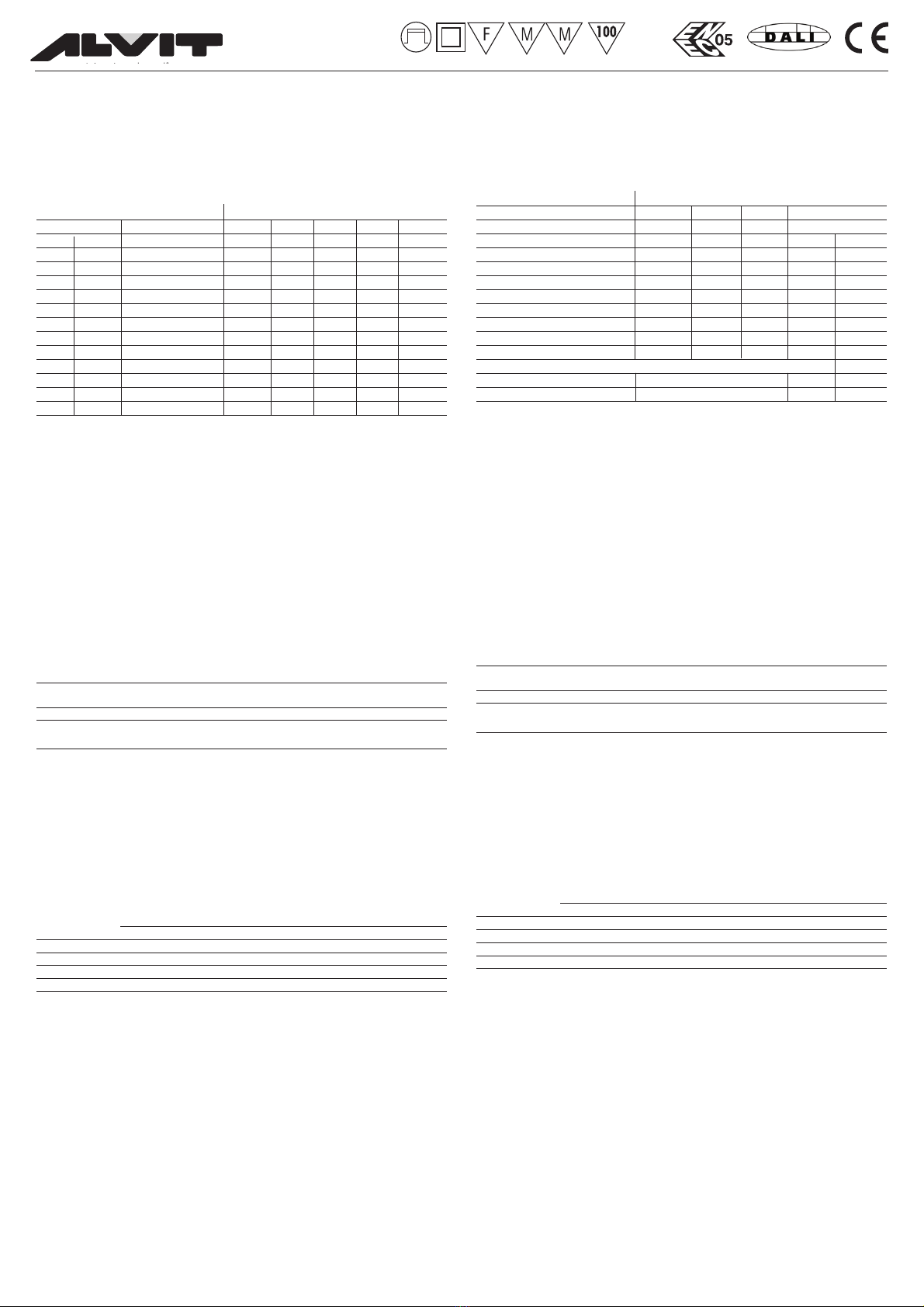
Output Dip-Switch position
220-240V Output 12345
17W CC 350mA 9-48V -----
19,2W CC 400mA 9-48V - - - ON -
21,6W CC 450mA 9-48V ON ON - ON -
24W CC 500mA 9-48V ON ----
26,4W CC 550mA 9-48V - ON - - -
28,8W CC 600mA 9-48V ON ON - - -
30W CC 630mA 9-48V ON - - ON -
33,6W CC 700mA 9-48V - - ON - -
38,4W CC 800mA 9-48V - ON - ON -
41W CC 850mA 9-48V ON - ON - -
43W CC 900mA 9-48V - ON ON - -
40W CC 1A 9-40 V ON ON ON - -
24W CV 24V - 1A max ON ON ON - ON
Dimming Dip-Switch position
Dimming 1 2345
ON/OFF - - - - -
Push Slow ON - - -
Push Fast - ON - -
Push Up/Down ON ON - -
DALI - - ON -
1-10V for passive resistor - ON ON - ON
1-10V for active systems - ON ON - -
0-10V for active systems ON - ON - -
0-10V for passive resistor ON - ON - ON
Slave ON ON ON - -
MASTER -
FAN ON
Valore NTC Temperatura inizio intervento Temperatura spegnimento 10%
0,5V --> 1K7ΩReq 0,25V --> 0K9ΩReq
10K 70°C 90°C
Esempio di Tabella intervento NTC Esterno.
Verificare caratteristiche NTC in uso per effettive temperature di intervento limitazione Duty Cycle PWM.
NTC di riferimento: EPCOS, B57703M0103G040
OUTPUT SET
DIMMING SET
Ingresso
> Nominale: 220/240 Vac 50/60 Hz.
> Idoneo per funzionamento a range esteso 90-264V - 50/60Hz con declassamento della potenza.
Contattare l’ufficio tecnico
> Morsettiera 1 x 2,5 mm2.
> Serracavo per cavi diametro Ø = 3...8 mm.
> Corrente massima: 0,25 A.
> Fattore di potenza λ: >0,9
> Armoniche corrente assorbita: secondo EN 61000-3-2.
Uscita
> Isolamento SELV.
> Morsettiera 1 x 0,5...1,5 mm2.
> Serracavo per cavi diametro Ø = 3...8 mm.
> Selezione corrente e tensione di uscita tramite DIP SWITCH (vedi tabella).
> Uscita ausiliaria isolata 12V - 100mA max per pilotaggio ventola Led.
La ventola allo start-up si accende con un ritardo di circa 2secondi.
> Connettore per collegamento NTC esterna per riduzione corrente carico:
diminuzione lineare della luminosità da 0,5V (100%) a 0,25V (10%).
Ambiente
Temperatura ambiente massima Ta: -10÷50° C (-10÷45° C per i modelli 800/850/900/1.000mA)
Temperatura max sul punto Tc: 75°
Normative
EN61347-2-13, EN61347-1, EN62384, EN62384, EN55015, EN61000-3-2, EN61547,
IEC 62386-101; IEC 62386-102.
Protezioni
> Protezione al cortocircuito, sovraccarico, circuito aperto e termica
> Fltro antidisturbo EMI
Isolamenti
Pri PUSH or DALI 1..10 V SEC
Pri — Basic Double Double
PUSH or DALI Basic — Double Double
1..10 V Double Double — Functional
SEC Double Double Functional —
ATTENZIONE: per mantenere l’isolamento SELV ed evitare di danneggiare il driver, collegare ai terminali
0..10 o 1..10 solo sistemi con isolamento rinforzato.
Regolazioni
> Sono previste cinque distinte modalità di funzionamento lette all’avvio (le impostazioni devono essere
fatte tramite dip-switch prima dell’accensione):
1) Push (tasto) no dimming, solo On/Off con rampe in accensione e spegnimento
2) Push (tasto) dimming - profilo lento, profilo veloce, profilo su/giù
3) DALI
4) Dimming 1-10V, riduzione della luminosità fino ad un minimo prefissato senza mai spegnere
5) Dimming 0-10V, riduzione della luminosità fino al completo spegnimento
> 1-10V/0-10V e Push sono in alternativa tra loro;
> Tempo dimmeraggio (0-100%; 100-0%): profilo A 10 secondi, profilo B 5 secondi;
> Livello Low in Push è diverso da 0 per distinguerlo da OFF.
> Riaccensione dopo mancanza rete:
- se in modalità no dimmer (On/Off), parte dall’ultimo dato impostato;
- se in modalità dimmer 0-10V o 1-10V è letto il valore in ingresso e ON in accordo alla programmazione;
- se in modalità dimmer Push, parte dall’ultimo dato impostato.
Nota profilo No dimming
> Pressione breve del tasto per ON/OFF (rampe in accensione e spegnimento)
Electronic ballast for LEDs, multi-multicurrent with active PFC. Suitable for voltage LED strips and power cur-
rent powered LEDs. The function mode is selected by means of the DIP SWITCH, which is below the termi-
nal cover.
Light regulation via DALI, push function, interface 1-10V or 0-10V suitable for use with either resistive poten-
tiometers that active systems like Gateway, Interfaces Konnex, touch screen, etc.
Valore NTC Temperatura inizio intervento Temperatura spegnimento 10%
0,5V --> 1K7ΩReq 0,25V --> 0K9ΩReq
10K 70°C 90°C
Example of Table NTC
Check NTC characteristics for use in actual operating temperatures limitation PWM Duty Cycle
NTC reference: EPCOS, B57703M0103G040
Input
> Nominal: 220/240 Vac -10/+10 % 50/60 Hz.
> Suitable for operation at extended range 90-264V - 50/60Hz with power derating of 50%. For further
information contact technical departement
> Terminal block for up to 1 x 2,5 mm2.
> Strain relief for cables with diameter Ø = 3...8 mm.
> Max Input Current: 0,25 A.
> Power factor
λ
: >0,9
> Harmonic content of mains current: according to EN 61000-3-2.
Output
> SELV insulation on output
> Terminal block for up to 1 x 0,5...1,5 mm2.
> Strain relief for cables with diameter Ø = 3...8 mm
> Selection of current and voltage output through DIP SWITCH (See table up)
> Isolated Auxiliary Output 12V - 100mA max for LED fan. For dimming less than 50% the fan is turned off.
At start-up the fan switch on with delay of about 2 seconds.
> Terminal block for external NTC signal for load current reduction:
linear decrease of brightness of 0,5 V (100%) to 0,25 V (10%).
Ambient
Ambient temperature Ta: -10÷50° C (-10÷45° C models 800/850/900/1.000mA)
Max case temperature on Tc: 75°
Normative
EN61347-2-13, EN61347-1, EN62384, EN62384, EN55015, EN61000-3-2, EN61547
IEC 62386-101; IEC 62386-102.
Protezioni
> Against input overvoltages from mains, short circuit and open circuit.
> Flter EMI suppression
Isolamenti
Pri PUSH or DALI 1..10 V SEC
Pri — Basic Double Double
PUSH or DALI Basic — Double Double
1..10 V Double Double — Functional
SEC Double Double Functional —
CAUTION: to maintain the SELV and prevent driver damage, connect to terminals 0..10 or 1..10 only
systems with reinforced insulation.
Settings
> There are five distinct modes of operation read on startup (the settings have to be made by dip-switch
before ignition):
1) Push button, no dimming - only On/Off soft
2) Push button dimming - Profile slow, Profile fast, Profile up/down;
3) DALI
4) 1-10V Dimming, reducing the brightness up to a predetermined minimum without
ever switch off
5) 0-10V Dimming, reducing the brightness up to switch off
> 1-10/0-10V and Push are alternatives to each other.
> Time dimming (0-100%, 100-0%): profile A slow 10 seconds, profile A fast 5 seconds;
> The low level in Push is different to 0 to distinguish it from OFF
> Restart after a power failure:
- If no dimmer mode, the last data set
- If dimming 0-10V or 1-10V input value is read and ON according to the scheduling
- If you can dim Push, the last data set
Note profile No dimming
> Briefly press button for ON / OFF (on and off ramps)