Amada LP1173173 User manual

Y01OM1173243-10
OPERATION MANUAL
FIBER COOLING CHILLER UNIT (200-230V AC)
LP1173173

LP1173173
Thank you for purchasing our Fiber Cooling Chiller Unit (200-230V AC) LP1173173.
・This operation manual explains its method of operation and precautions for use.
・Before using, read this operation manual carefully; after reading, save it in a proper place
where you can easily access.
Contents
1. Configuration ............................................................................... 1
2. Name and Functions of Each Section........................................ 2
3. Installation and Preparation........................................................ 3
4. Maintenance
(1) Replacing the Replacement Cartridge of the DI Filter .............. 12
(2) Replacing the Filter Cartridge ................................................... 14
(3) Inspecting Water Leaks from the Pump.................................... 15
(4) Cleaning the Dust-proof Filter................................................... 16
(5) Cleaning or Replacing the Union-type Small Line Filter ........... 17
5. Alarm Code................................................................................... 18

LP1173173
1
CAUTION
For handling of thermo chiller and flow switch, refer to the attached operation
manual.
1. Configuration
Part Name Model No. Q’ty
Thermo chiller (HRS012-A-20-MT) PZ1173142 1
Alarm detecting cable (20 m) AS1172750 1
Different diameter coupling 8-6 for
stainless pipe SKUSDK8-6 4
Coupling for stainless pipe SKUTK8 2
Insert material SKITK8 10
SKITK6 4
Polyolefin tube (20 m) TPH0806W-20 2
Soft polyolefin tube (1 m) TPS0604W 1
NFH tightening spanner PA1173184 1
Power cable PZ1169303 1
DI filter cartridge HRS-DF001 1
Ferrule pack for reconnecting the
coupling SKFPK8 2
Option
Part Name Model No. Item No.
Alarm detecting cable (5 m) AS1172751 1172751

LP1173173
2
2. Name and Functions of Each Section
Thermo chiller Controls the water temperature.
The recommended setting temperature is 27°C (no
condensation).
Electrical resistivity sensor Monitors the resistance value of cooling water.
DI filter Controls the resistance value of cooling water.
Flow switch Monitors the cooling water flow rate.
Filter housing Housing for the filter cartridge.
Filter cartridge Removes impurities from the cooling water.
Valve Used when replacing the filter cartridge.
Flow regulator Adjusts the flow rate.
Pressure switch Monitors the pressure of cooling water.
LP1173173
3
3. Installation and Preparation
This chapter explains where to install the thermo chiller and cooling water.
Installation Place
Follow the attached operation manual for the thermo chiller.
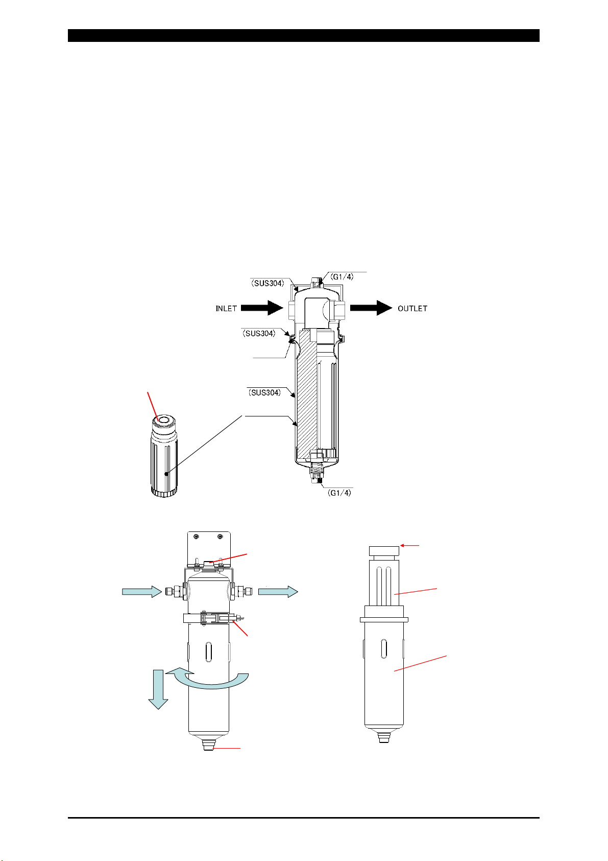
Mounting the DI Filter Replacement Cartridge
Since the DI cartridge deteriorates on contact with the air, it is packed separately.
Mount it before use.
1) Mount the a replacement cartridge with the seal part up. (See figure below.)
入口 出口
通気栓
ドレン栓
固定金具
緩む
入口 出口
通気栓
ドレン栓
固定金具
緩む
DIフィルター
交換用カートリッジ
シール部
DIフィルター
交換用カートリッジ
シール部
Seal part
DI filter
Replacement cartridge
Seal part
Drain plug
Ventilation plug
Loosen
Inlet OutletOutlet
Clamp
Cove
r
O-ring
Case
DI filter
cartridge
Air vent
V band
Drain

LP1173173
4
2) Mount the lower half of the DI filter with the reverse procedure to removing it.
3) Close the clamp.
4) Mount the drain plug.
5) Close the ventilation plug.
6) Start the thermo chiller with the valve of the DI filter closed.
7) Open the valve on the thermo chiller’s RETURN side only.
8) Open the ventilation plug to remove air, and close it again.
9) Open the valve on the thermo chiller’s OUTLET side.
⇒Check for leaks.
⇒When the cartridge is replaced, the water level of the cooling water tank will
drop. In that case, supply the cooling water.
Cooling Water
Use the cooling water meeting water quality standard established by Japan
Refrigeration and Air Conditioning Industry Association (JRA GL-02-1994 / cooling
water system - cyclic water - makeup water). (Cooling water supplied with the Laser
or distilled water is recommended.)
Tap water, water for industrial use, or ground water may cause corrosion or
clogging, resulting in fault of the equipment.
Connections and Preparations of Each Section
1) Connecting the power supply
When using the attached power cable (PZ1169303), use the terminal suitable for
the terminal block on the customer side.
For wiring, follow the attached operation manual for the thermo chiller.
200-230V AC
L
A
pprox.
3
m
A
pprox.
100
mm
Clr.: WHT
Clr.: BLK
Clr.: YEL/GRN
N
PE
LP1173173
5
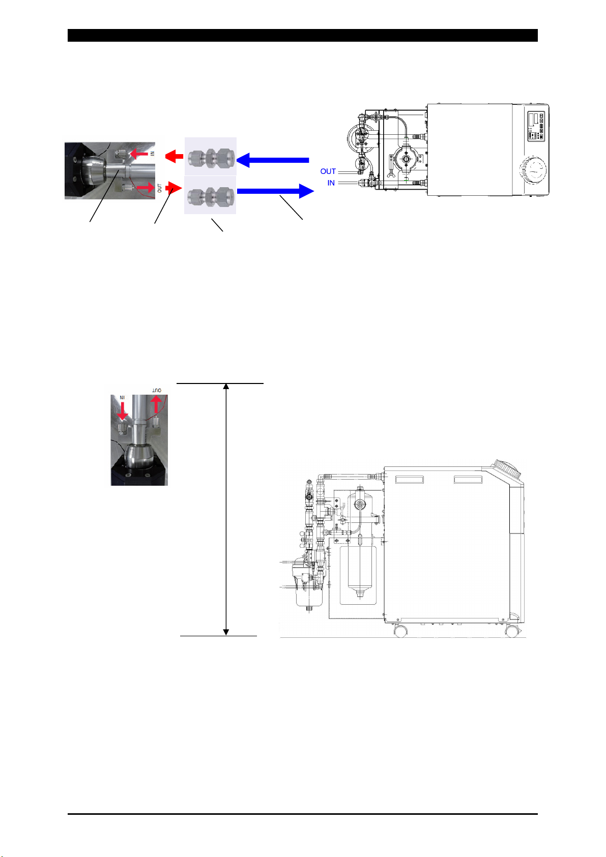
2) Connecting the tube
Note 1 Tube, TPH0806W-20
Cut the tube into any length in the range of 20 m on each side of IN/OUT.
(Since the required flow can not be secured with a tube over 20 m long, the flow
rate error will occur.)
Install the fiber connector 2.5 m or less from the floor.
Secure the minimum bending radius 100 mm.
Coupling,
SKUSDK8-6
(Note 2)
Tube,
TPH0806W-20
(Note 1)
Tube,
TPS0604W
(Note 3)
Fiber connector
(Note 4)
2.5 m max.

LP1173173
6
When cooling plural optical fibers:
・Up to two optical fibers can be cooled.
・Connect optical fibers in parallel as shown below.
・The maximum length of cooling tube should be 40 m in total. (+++++=
40 m max.)
Note 2 Coupling, SKUSDK8-6
Be sure to insert the insert material (SKITK8 or SKITK6) before connection.
Insert material (SKITK8 or SKITK6)
[Connection method]
a. Without removing the nut, insert the tube into
the coupling and push the end of the tube all
the way in.
b. Tighten the nut with a hand until it stops
moving. Put a mark in this position.
c. Rotate the nut 450 degrees clockwise with a
spanner, keeping the coupling body with
another spanner from moving.
SKUSDK8-6
SKUTK8
SKUTK8
SKUSDK8-6 SKUSDK8-6
SKUSDK8-6

LP1173173
7
[Reconnection method]
a. Before loosening the nut, check its
position. (This position is used as a
reference in the Step d.)
b. Remove the nut.
Check again that the front ferrule is
mounted at the proper position.
Check that no foreign matter is attached
to the body.
c. Insert the front ferrule until it attaches
firmly to the body and tighten the nut
with a hand.
Take care not to scratch the body with
the end of the tube.
d. Tighten the nut with a spanner until it
goes slightly over the position before
loosened (15 to 30 degrees).
Note 3 Tube, TPS0604W
It is recommended that the length be 100 mm or shorter on each side of IN/OUT.
When the length is longer than 100 mm, the pressure loss becomes greater and
a flow rate error may occur.
Note 4 Fiber connector
・Confirm that the optical unit is connected before fitting pipe.
・Confirm that the Laser is turned off.
・Be careful about IN and OUT.
100 mm or shorter
recommended
Coupling,
SKUSDK8-6
SKFPK8
Ferrule pack for recon-
necting the coupling
LP1173173
8
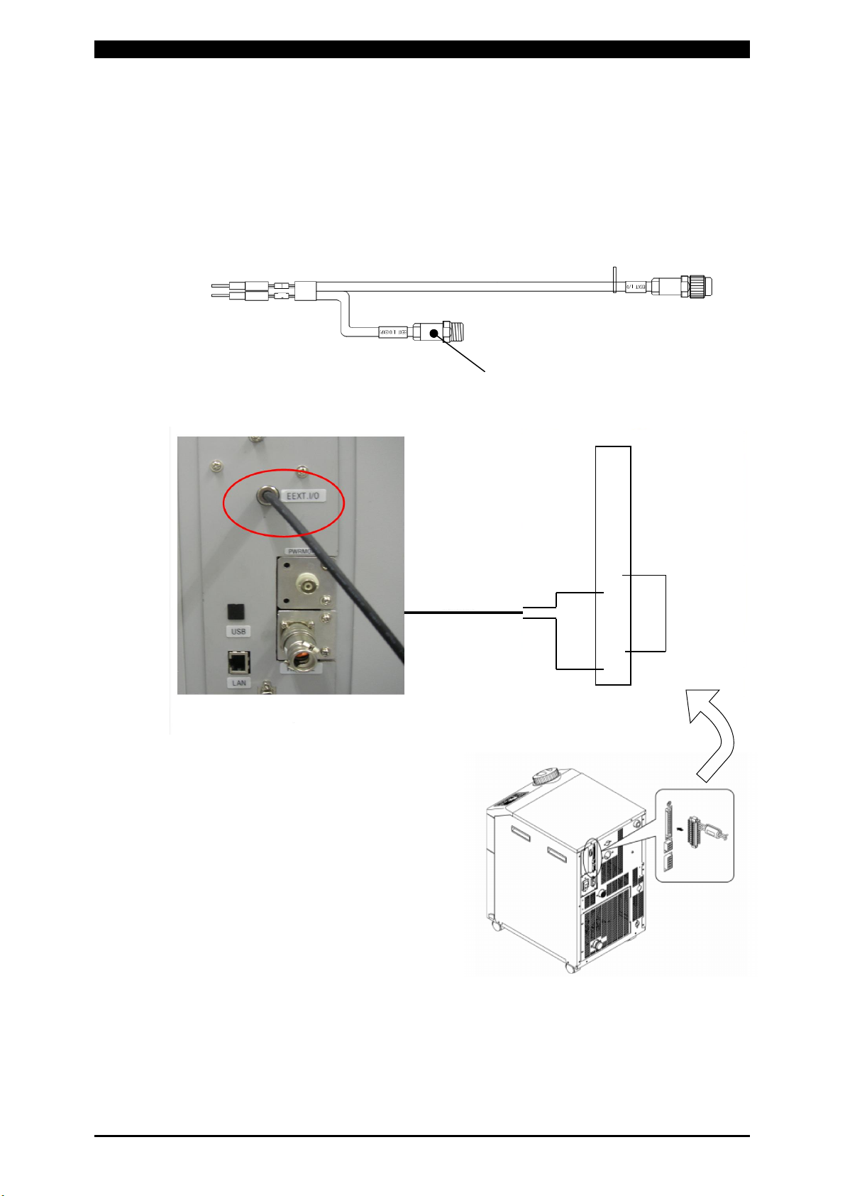
Wiring
・For the AC power cable connection, follow the attached operation manual for the
thermo chiller.
・Connect the alarm detecting cable (attached AS1172750 (20 m) or optional
AS1172751 (5 m)) to the Laser. Connect the EEXT. I/O (AS1172786)
disconnected from the Laser to the jack side of the alarm detecting cable.
To detect the alarm of the thermo chiller, connect the cable to Nos. 1 and 5.
Jack side
Alarm detecting cable
Connection
Laser rear Thermo chiller rear
5
12
11
10
9
8
7
6
5
4
3
2
1 AAS1185835
Alarm detecting cable
Table of contents
Popular Chiller manuals by other brands

Trane
Trane RTAA-70 Installation & maintenance guide

Carrier
Carrier Omnizone 50BVC Installation, Start-Up, Service and Controls Operation and Troubleshooting

York
York YGWH 115 Installation, commissioning & operation

Galletti
Galletti PERFORMA MPE Series Technical manual

SMC Networks
SMC Networks HRR Series manual

Daikin
Daikin EWAQ016CAW Installation and operation manual


