Telemark TVP-2000 Manual

Page i of 1
TVP Manual (full) March 2007 CE rev 03.doc
Operation, Installation and Service Manual
Water Vapor Cryotrap
Models TVP-2000 and TVP-3500

Page ii of 2
TVP Manual (full) March 2007 CE rev 03.doc
Tele ark Cryotraps TVP2000/3500

Page 3 of 3
TVP Manual (full) March 2007 CE rev 03.doc
Table of contents
Read this first - Health and Safety advice
Introduction
Section 1 Syste s Operation
1.1. Local ( anual ode using the front control panel)
1.2. Re ote ode operation of a TVP using the 37 pin isolated interface
1.3. Full co puter ode re ote operation using RS232 or other
co unication standard
1.4. Operators quick reference guide
Section 2 Installation Guide
2.0 Unpacking, inspection and installation require ents
2.1 Preparation of cryo-coil and refrigerant lines
2.2 Configuration of re ote interface
2.3 Full co puter ode re ote operation using RS232 or other
co unication standard
2.4 Calibration routine “cal2309”
2.5 Preparation for operation
2.6 Deco issioning
Section 3 Trouble Shooting guide
3.0 TVP 4 essential sub syste s
3.1 Initialisation and start up
3.2 Proble s during cool
3.3 Proble s during defrost
3.4 Interface and re ote control
Section 4 Tables and data
4.10 Description of electrical supplies, and controls electrical and syste
sche atics
4.11 Syste with side panel re oved showing ain sub-syste s
4.20 Interfacing to the TVP
4.30 Principles of operation
4.40 Description of safety syste s
4.50 Cooling curve TVP odels
4.60 The design and place ent of cryo-coils
4.70 Reco ended spare parts list
4.80 Materials safety data sheet
4.90 CE Certification
4.95 Chinese Hazardous Substances Concentration Table
Section 5 Warranty
5.0 Li ited Warranty for Tele ark Water Vapor Pu ps
Glossary

Page 4 of 4
TVP Manual (full) March 2007 CE rev 03.doc
WARNINGS
THE PHRASE WARNING IS USED WHERE THERE IS A HIGH PROBABILITY OF PERSONAL
INJURY OR DEATH SHOULD THE PROVISIONS HIGHLIGHTED BE IGNORED. IT IS THE DUTY
OF BOTH THE INSTALLER/OWNER AND OPERATOR OF THE EQUIPMENT TO BE FAMILIAR
AND COMPETENT WITH THE OPERATION AND USES OF THE PRODUCT. HELP MAY BE
SOUGHT FROM THE MANUFACTURER.
(1) The syste contains specific hazards, which present a significant danger to personal
safety;
(a) high voltage electrical co ponents and high-pressure refrigerant gases, which are
a significant frostbite hazard.
(b) refrigerant gases, which will cause asphyxiation in confined areas.
(c) refrigerant gases, which if exposed to high te peratures deco pose to for very
toxic by-products – never s oke in the vicinity of a TVP or any other si ilar syste
including the gas cylinders.
(d) water in close proxi ity to high voltage electricity.
(e) hot and cold surfaces which represent a significant burn / frostbite hazard.
(2) the syste contains gases under pressure, which ay constitute both a frostbite hazard
and a burn hazard. Refrigerant gases are known asphyxiants and are ildly narcotic.
Precautions ust be taken and work ust only be carried out by suitably qualified personnel.
(3) re oval of any panels other than the front door will expose the operator to high voltage
co ponents, which ay result in a fatal electrocution
(4) failure to leak test the syste as a whole ay result in the catastrophic release of
refrigerant, which presents a very high risk fro frostbite and or asphyxiation. See e ergency
shut down procedures and the aterial safety data sheet for guidance.
(5) during installation there is the potential to be exposed to high voltage co ponents (up
to 400v ac), which ay result in a fatal electrocution.
(6) TVP units ust always be operated with a suitable ground/earth line. Failure to co ply
ay result in fatal electrocution. Never ta per with or re ove any ground/earth connection
fro inside of the achine.
(7) isolate syste before connection. Ensure the connection cable used is co pliant with
local electrical require ents. Cabling within the unit is tri-rated to CSA / UL / CE nor s. There
should be three power wires and one ground wire; there is no neutral line. Feed cable through
gland and ter inate at ain syste isolator, having first re oved the protective cover.
Ground the TVP at pri ary ground point.
(8) failure to replace isolator cover exposes operators to potentially fatal electrocution. It
is essential this pri ary protection always be in place before the syste is energised.
(9) always isolate the syste through the ain circuit breaker before attaching the re ote
control. When in re ote operation take additional care to prevent personal injury,

Page 5 of 5
TVP Manual (full) March 2007 CE rev 03.doc
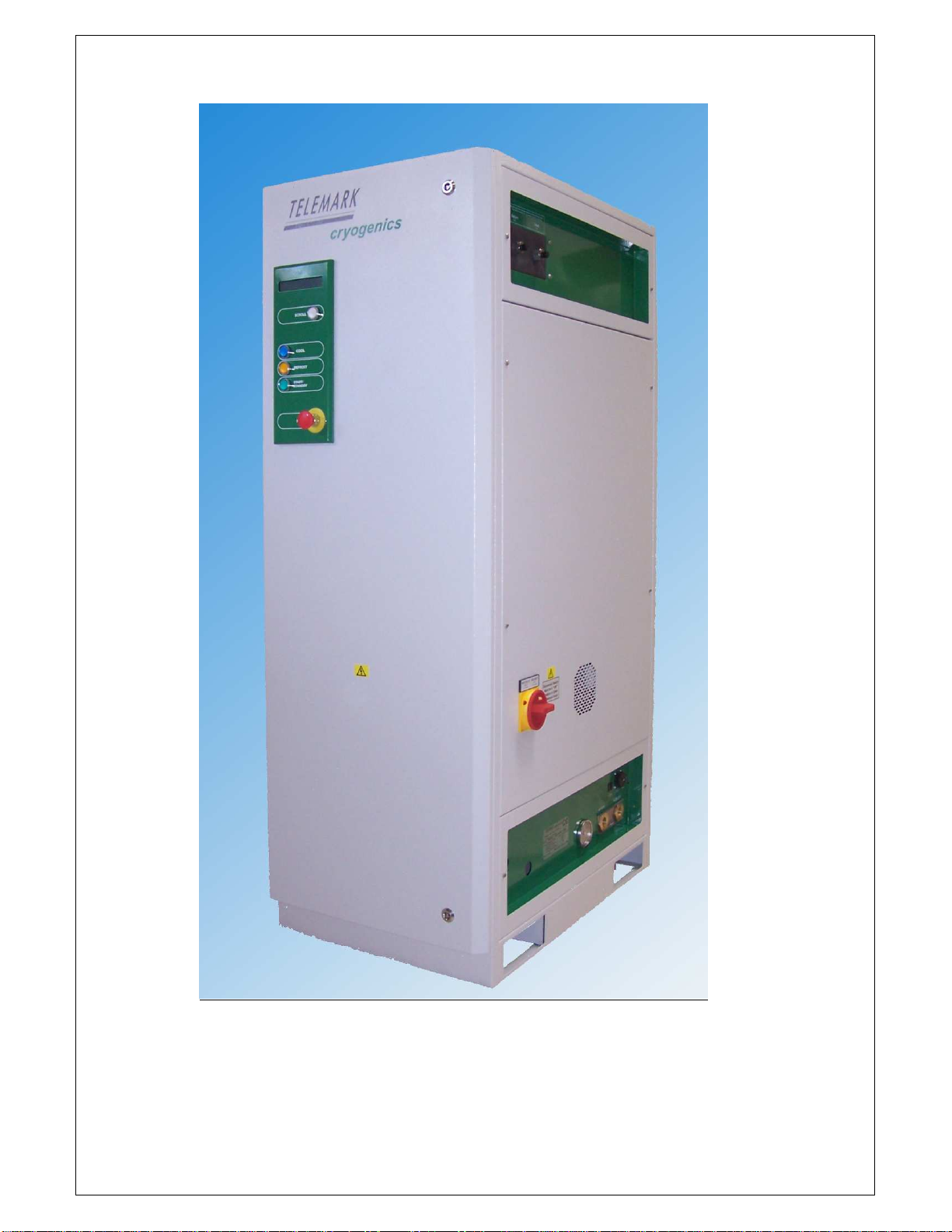
as viewed from right hand side.
(10) the refrigeration syste contains a ixed blend of refrigerants and polio-ester oil. These
do not present acute health risks it is essential that the following basic precautions are
followed:
(a) always wear eye protection.
(b) always wear surgical type rubber or latex gloves.
(11) the syste contains specific hazards, which present a significant danger to personal
safety
(a) high pressure refrigerant gases, are a significant frostbite hazard.
(b) refrigerant gases will cause asphyxiation followed by death in confined areas.
(c) refrigerant gases, which if exposed to high te peratures deco pose to for very
toxic by-products – never s oke in the vicinity of a TVP or any other si ilar syste
including the gas cylinders.
CAUTIONS
The phrase Caution indicates a risk of da age to the product or associated plant and
achinery if the provisions are not followed carefully.
(1) Tele ark will not be responsible or liable for either direct or consequential personal
injury or loss clai s arising fro the isuse of the product.
(2) Unit contains pressurised gas. Do not open hand valves until syste is connected to a
Cryocoil, which has been checked for leaks. Do not connect the syste to other syste s
unless their design and application has been approved by the anufacturer.
(3) Closure of the hand valves whilst the syste is at cryogenic te peratures ay da age
the valve seats and invalidate the syste s warranty. It ust only be atte pted on a
cryogenically cold syste in the case of an e ergency, which is causing gross leakage fro
the Cryocoil or refrigerant lines.
(4) Do not connect the TVP to an existing Cryocoil without insuring that the Cryocoil will
accept the operating pressure of the TVP syste and that the whole syste has been fully
leak checked. Failure to do so could da age the coil and the vacuu syste .
(5) The Cryocoil should be no less than 1/2 inch or 13 away fro the cha ber wall or
any other object including other parts of the Cryocoil. Failure to co ply will reduce efficiency.
It is bad practice to ount the Cryocoil directly onto a etal plate.
(6) Access to two sides ust be aintained: The front/control panel and the right side
cooling water/refrigerant line/power/re ote control points. No such require ents are
necessary for the left side or back of the TVP unit. Although a clearance of 70 to allow the
door to open fully is required on the left hand side of the unit.
(7) The correct orientation of the flow is essential if the full potential of the unit is to be
realised:
Inlet to coil on the right }
Outlet fro coil on the left }
(8) The TVP is phase sensitive, if connected in the wrong orientation the unit will not
operate correctly. No da age can be caused by incorrect orientation of the phases.
(9) Poor water vapour pu p perfor ance is often caused by poor insulation or by water
collection on the refrigeration lines.

Page 6 of 6
TVP Manual (full) March 2007 CE rev 03.doc
(10) If the lines have visible frosting or water is seen to leak fro the during defrost or
standby, all of the line insulation ust be replaced.
(11) The ost co on cause of syste alfunction are refrigeration leaks. Careful
attention to the integrity of the syste will ensure opti al perfor ance.
(12) Do NOT repeatedly bend the refrigerant line; this will cause leakage and or breakdown
of the insulating aterials.
(13) Always attach the refrigerant line to the feed-through coupling.
(14) Leak checking should always be carried out with a heliu ass spectro eter leak
detector. Any other ethod ay lead to conta ination of the syste , leaks and ulti ately
syste failure.
(15) Detecting leaks without a heliu ass spectro eter is difficult and ti e consu ing for
all but the grossest of leaks. The leak rate should be less than 5 x 10
-8
bar/L/S this is outside
of the detection range of hand held halogen sniffer.
(16) Most leaks are found at the connections of refrigerant lines, pay particular attention to
these areas. It is i portant that these joints are checked regularly throughout the life of the
installation.
(17) Failure to identify and repair leaks before operation will lead to poor perfor ance
syste conta ination and in extre e cases total syste failure. In such cases the Warranty
will be invalidated.
(18) Ensure the Cryocoil is located in a vacuu cha ber and that the cha ber is evacuated
to at least 0.01 Torr or 1 x 10
-2
bar to prevent overheating of the coil fro latent heat.
(19) Before any leaks are repaired the refrigerant ixture ust be drawn back into the TVP
unit. Using an oil free refrigerant reclai unit. This requires an experienced technician.
Details of how this aybe achieved are outside the scope of this anual.
(20) Do not operate the unit if a refrigerant leak is suspected. Be very careful not to pull a
vacuu within the refrigeration lines as this will lead to conta ination of the syste by water.
(21) Failure to adequately insulate and protect refrigerant feed lines and couplings will result
in reduced cryotrap perfor ance, including possible failure of the entire syste .
(22) The syste uses highly stable PT100 sensors, the te perature easure ent syste is
designed for long-ter reliability and stability of te perature easure ent. Inferring vacuu
perfor ance fro the CI/CO values is an unreliable ethod of process deter ination. Direct
easure ent and observation of the vacuu through either an RGA or Penning type gauge
are the only reliable ethods of evaluating the actual process conditions present.
(23) For process safety reasons the interface has the following co and hierarchy:
COOL - Overrides all other actions.
DEFROST - Will revert to STANDBY when co plete.
STANDBY - Default state.
(24) To prevent syste da age check controlling syste s status and the interface is
correctly wired before atte pting to connect to the TVP.

Page 7 of 7
TVP Manual (full) March 2007 CE rev 03.doc
(25) Do not short circuit the 24 V AC supply (pins 35 & 36) against any pin designated as
ground (GND) as this ay da age the low voltage circuitry. The syste is protected by a
anual re-settable 2-A p ther al fuse located on the left hand side of the re ote connector.
Ensure that there is sufficient resistance in any external circuit to prevent this value being
exceeded.
(26) The re ote is fully isolated, there will be a s all AC potential difference above the
chassis ground/earth. It is i portant to understand that switching can only be achieved
against the ground of the re ote interface as opposed to the earth of the unit.
(27) The onboard co puter protects the syste fro isuse therefore it ay not always be
possible to ake the syste functional. You ay need to wait a short ti e before engaging a
different ode.

Page 8 of 8
TVP Manual (full) March 2007 CE rev 03.doc
TELEMARK TVP SERIES
Classically a TVP is used with an evaporative surface (Meisner/cryo-coil), which is located
within the vacuu cha ber. When in this configuration a Tele ark TVP is an ultrahigh
perfor ance vacuu pu p capable of pu ping water vapor and other condensable gases at
speeds far in excess of conventional vacuu pu ps.
Your TVP uses the latest advanced heat exchanger and refrigeration technology to give
industry leading energy and vacuu perfor ance.
A Tele ark TVP couples speed with a sophisticated co puter control package which includes a
si ple and adaptable user interface with isolated interface and RS232 / 485 co s package
as standard.
The ranges of tasks to which your TVP can be applied are not li ited to pu ping water vapor
in vacuu . Many are used as substrate coolers (chuck coolers) or other applications where a
continuous level of high power cooling in the range –100 to –150
o
c is required.
Your invest ent in a Tele ark TVP is backed by a 1-year warranty, which is detailed at the
end of this anual.

Page 9 of 9
TVP Manual (full) March 2007 CE rev 03.doc
Diagra 1 External view of TVP

Page 10 of 10
TVP Manual (full) March 2007 CE rev 03.doc
Section 1 Syste operation
At any ti e a TVP syste and in any control ode aybe safely turned off by depressing the
stop / e ergency off (EMO) button. (Figure 1)
The following section assu es the syste has been installed correctly and covers the following
odes of operation.
Warning:
Vacuu syste s present any hazards, take ti e to read this anual and fa iliarise yourself
with your installation
1.1 “Local” ( anual) ode using the front control panel
A TVP water vapor cryotrap is fully protected by a sophisticated co puter control syste ,
which allows very si ple anual operation.
The on board co puter protects the syste fro isuse therefore it will not per it operation
when syste para eters are outside acceptable values. Likewise you ay need to wait a
short ti e before engaging a different ode. At any ti e while the syste has power it is
possible to use the scroll button, which re ains illu inated at all ti es.
Diagra 2 The display panel
Display character
ne onic
Meaning Units
DP Discharge pressure Psi
SP Suction pressure Psi
CT Coldest syste te perature (internal easure ent)
O
C
CI Coil in (outlet / flow fro unit) te perature
O
C
CO Coil out (inlet / return to unit) te perature
O
C
CI2 Second coil value – only dual coil units
O
C
E(n) Syste error where n = an integer
Caution
It is good practice to note the balance pressure SP or DP and the coldest te perature CT
before starting the syste after any extended period of shut down as this can pin point a leak
on the refrigeration lines or cryo-coil.

Page 11 of 11
TVP Manual (full) March 2007 CE rev 03.doc
1.101 Resetting the syste
To reset the STOP button after actuation it ust be turned 90o clockwise, at which point it will
click outwards, all other buttons have a o entary actuation. The TVP will auto atically
reset itself after a forced stop, a anual start or renewed re ote start signal are required for
restart. If the unit is ready for operation the green start / standby button will illu inate. The
illu ination of the action buttons is independent of the control ode they also provide status
indication.
If the syste fails to operate the over pressure trip ay have been triggered see diagra 12
in trouble shooting guide on resetting co pressor over te perature and pressure protection.
1.102 Switching the syste on
Depressing the illu inated start / standby button will start the syste – in the case of a dual
coil unit only one of the start / standby buttons will illu inate this is nor al. The syste will
start and the display will read “Pre-cool”. On a TVP3500 a single co pressor starts initially
when a CT value of less than –100
o
c is achieved the second co pressor will start.
When the syste is in the Pre-cool ode all other odes of operation are disabled, until
predefined conditions are et none of the control buttons will illu inate in this state. At the
end of the pre-cool phase the Start / Standby button will illu inate to indicate the syste is
able to start cooling. At all ti es the scroll button re ains illu inated
1.103 Standby
Standby is the nor al “resting state” both cool and defrost ay be selected when the standby
light is illu inated, however defrost will ter inate instantly if the CO value is higher than the
defrost ter ination value. In standby the display shows DP and SP.
1.104 Cool
Pressing the blue cool button activates the cool solenoid valve, allowing refrigerant to flow
around the cryo-coil. The syste display auto atically switches fro displaying DP and SP to
the te perature of the coil inlet and outlet (CI & CO). When the syste is in cool the button
will re ain illu inated.
1.105 Defrost
At any ti e defrost can be initiated by pressing the orange defrost button. Following the
initiation of defrost the cool solenoid valve is closed and the defrost valve is opened an audible
click will be heard. When the syste is in “defrost ode” the button will re ain illu inated.
During defrosting hot gas passes directly fro the co pressor into the cryo-coil causing very
rapid heating. The syste onitors the returning gas te perature, and discharge pressure in
deter ining if the cryo-coil has been defrosted. For protection of the syste it will ter inate
defrost and auto atically enter standby if greater than 4 inutes have elapsed following the
initiation of defrost. If defrost ter inates pre aturely check the discharge and water
te peratures first.
When defrost ends the syste auto atically enters standby this is indicated both on the
display and by the button illu ination changing.

Page 12 of 12
TVP Manual (full) March 2007 CE rev 03.doc
1.106 Syste Recovery after defrost
After defrost it is possible to enter cool i ediately however, better results (faster cycle ti es
and lower te peratures) are achieved if a short period ( ore than 4 inutes) in standby is
allowed for the syste to recover. The recovery period is in proportion to the defrost
ter ination te perature and the duration of the defrost cycle. A longer defrost period and the
higher ter ination te perature both increase the recovery period. A good rule of thu b is if
the discharge pressure is less than 160 psi then it is fully recovered.
Re ote display of syste status in anual ode can be achieved by using the syste
condition signals fro the re ote interface, which re ain active at all ti es. The analog
output also reads the coil out condition.
1.2 Re ote ode operation of a TVP using the 37 pin isolated interface
All buttons apart fro scroll and the e ergency off button are disabled by connection of the
re ote. The syste auto atically switches to re ote operation if a link between pin 9 and
24 is ade, this link is already ade in the ating connector supplied with the TVP.
The re ote is a fully isolated interface and irrors the operation of the front panel. Making a
connection between a syste ground pin and the appropriate co and pin will change the
syste s function.
Read back of syste function is retained by the buttons on the front panel beco ing
illu inated. The syste also has read back through the re ote connector via relays.
For process safety reasons the interface has the following co and hierarchy:
COOL – Overrides all other actions.
DEFROST – Will revert to standby when co plete.
STANDBY – Default state.
When the re ote connector is fully engaged the syste will auto atically switch fro “local”
to “re ote” operation. This is indicated on the front panel display. When in re ote operation
all control buttons apart fro the STOP / EMERGENCY OFF and SCROLL buttons are disabled.
WARNING
Always isolate the syste through the ain circuit breaker before attaching the re ote
control. When in re ote operation take additional care to prevent personal injury.

Page 13 of 13
TVP Manual (full) March 2007 CE rev 03.doc
1.3 Full co puter ode re ote operation using RS232 or other co unication standard
TVP units can be controlled or data logged via an integral RS232 port. The port is located on
the service panel (diagra 4). Connection to your PC is via your serial port to an RJ11 (US
style phone jack). Consult your PC anual or dealer for serial link cable and adapter. A
standard adaptor to 9 pin serial port can be obtained directly fro Tele ark.
Control is achieved using “hyper ter inal”, which is nor ally shipped with your Windows PC to
control and data log syste para eters.
Diagra 3
Having started hyper ter inal you are required to enter a connection na e
Diagra 4

Page 14 of 14
TVP Manual (full) March 2007 CE rev 03.doc
Hyper Ter inal Settings (assu es Windows 95 or newer)
Select the connect using box and set to your serial port (usually COM1)
Diagra 5
Select OK
You will auto atically be taken to COM1 properties window
Select the following settings
Bits per second = 9600
Data bits = 8
Parity = None
Stop Bits = 1
Flow control = Hardware
Diagra 6

Page 15 of 15
TVP Manual (full) March 2007 CE rev 03.doc
Enter return and the essage following will appear if a connection has successfully been
ade.
Diagra 7
Entering a query with a “? Return” will give the following screen
Diagra 8
Note
All co ands ust be executed as lower case characters followed by return. All co ands
apart fro the specialised calibration routine follow a three-character for at.
W2o
Turning the co s link on and allows both data logging (verbose ode) and control of the
TVP.
W2f
Turns the link off in this ode so only data logging is per itted

Page 16 of 16
TVP Manual (full) March 2007 CE rev 03.doc
Operational co ands
>Read Co ands ‘r’
Read co ands are used to interrogate the syste s and are very helpful when diagnosing
faults.
>Write Co ands ‘w’ are used to change status of the syste fro cool to defrost for
exa ple.
>------------------------------
>w2o – write 232 control ON
>w2f – write 232 control OFF
>wso – write Syste ON – switch unit on (standby)
>wsf – write Syste OFF – switch unit off
>wss – write Standby 1 – Standby ain or coil 1
>w2s – write Standby 2 – Standby coil 2 dual coil units only
>wsc – write Cool 1 – Cool or coil 1 dual coil units
>ws2c – write Cool 2 – cool coil 2 dual coil units only
>wsd – write Defrost 1 – defrost coil 1 or defrost
>w2d – write Defrost 2 – defrost coil 2 (dual coil units only)
>------------------------------
Please refer to the installation section of the anual for advanced instructions and detailed set
up guide.
To operate the TVP under RS232 the following typical control co and sequence would be
followed:
I. W2o – Turns RS232 control ‘on’
II. Wso – Turns TVP on
III. Wsc – Syste ‘cool’
IV. Wsd – Syste ‘defrost’
(co ands III and IV ay be repeated indefinitely at each cycle)
Wss – Places syste s in standby
Wsf – switches the TVP off

Page 17 of 17
TVP Manual (full) March 2007 CE rev 03.doc
1.4 Operators quick reference guide
Following syste para eters ranges are nor al any abnor al conditions will be reported via
the display and the RS232 link if enabled.
Para eter Description Acceptable (nor al) range
SP start up * Suction Pressure 20 to 120 psi
DP start up * Discharge pressure 100 to 470 psi
SP unit running 7 to 60 psi
DP unit running 100 to 380 psi
SP & DP unit off)
|
Syste balance at a bient 235 to 260 psi
CT Coldest te perature -100 to –170
o
C
WT Water te perature 35
o
C default 40
o
C optional
CI Coil in te perature +90
o
C to –150
o
C
CO Coil out te perature +40
o
C to –150
o
C
* Start up only
Balance pressure CT value to be obtained at sa e ti e.
Alar essages
Note all alar essages before resetting unit. Repeated alar essages can be an indication
of i inent syste failure or failure of the water supply.
The syste will shut down if control para eters are breached and an error essage will be
displayed: If a syste para eter is breached a anual reset is required. (actuate EMO and
resetting)
CAUTION
A forced anual reset eans it is the users responsibility to investigate and correct any cause
of error before re-starting
Error Code Display Message Means
E1 DP High Discharge pressure high
E2 SP Low Suction pressure low
E3 WT High Water te perature high (greater than 35
o
C)
E6 DT High Discharge gas te perature has exceeded 145
o
C
For an explanation of the error essages in relation to a possible fault see trouble shooting
section (3)
CAUTION
Greater syste perfor ance and reliability ay be achieved by following a few si ple
preventative observations
Daily checks
Frost build up on refrigeration lines or feed through. Excessive frost build up can lead to
fracturing of etal parts.
Syste running pressures after a predeter ined period of standby ideally at the beginning of
the working day.
Weekly checks
Syste balance pressure SP or DP when CT is above 0
o
C i.e. after 48 hours of shut down.
Typically Monday orning before syste restart.
Water chiller function
Water supply failure is the ost co on cause of an established syste failing
Annual check
Syste balance pressure SP or DP when CT is above 0
o
C

Page 18 of 18
TVP Manual (full) March 2007 CE rev 03.doc
Note
The syste uses highly stable PT100 sensors, the te perature easure ent syste is
designed for long-ter reliability and stability of te perature easure ent. Inferring vacuu
perfor ance fro the CI/CO values is an unreliable ethod of process deter ination. Direct
easure ent and observation of the vacuu through either an RGA or Penning type gauge
are the only reliable ethods of evaluating the actual process conditions present. The actual
vacuu relates to the su of the partial pressures of which water accounts typically 90-98%
within a vacuu syste . For further infor ation regarding the vapour pu ping of water
consult Section 4 vacuu data.

Page 19 of 19
TVP Manual (full) March 2007 CE rev 03.doc
Section 2 Installation Guide
Installation
WARNING
The syste contains gases under pressure, which ay constitute both a frostbite hazard and a
burn hazard. Refrigerant gases are known asphyxiants and are ildly narcotic. Precautions
ust be taken. Work ust only be carried out by suitably qualified personnel. Always wear
suitable eye and hand protection.
WARNING
All refrigeration work in which the refrigerant gas is oved or anipulated ust be done by a
qualified technician. Many national laws require individuals who perfor such work ust have
a certification of Refrigeration Technician. Other laws in various countries ight govern use or
service of this syste . Local regulations should be strictly adhered to. Particular attention
should be paid to the contain ent and recovery of refrigerants.
WARNING
The syste contains high voltage (either 208 or 415VAC) and high power co ponents. To
avoid the possibility of a fatal electrical shock always isolate the unit fro the ains supply
before working on the syste . A qualified technician should carry out the electrical work.
WARNING
Internal parts of the syste ay either be very hot, or very cold, presenting a possible burn
hazard. Always take precautions where the syste has been running within the last hour.
WARNING
Read the instruction anual before operation of the TVP Water Vapor Cryotrap.
CAUTION
Do not disconnect, alter or bypass any of the built in safety and protection devices. This will
void your warranty and possibly increase the risk of equip ent da age.
CAUTION
Unit contains pressurised gas. Do not open hand valves until syste is connected to a Cryo-
coil, which has been checked for leaks. Do not connect the syste to other syste s unless
their design and application has been approved by the anufacturer, and they have been
assessed for leak tightness.
CAUTION
Do not release refrigerant into the at osphere it is illegal and dangerous; please refer to your
local authorities instructions regarding the disposal of reclai ed refrigerants. Read the
Material Safety Data Sheet before installing the syste . Verify co pliance to your local
require ents.
CAUTION
Closure of the hand valves whilst the syste is at cryogenic te peratures ay da age the
valve seats and invalidate the syste s warranty. It ust only be atte pted on a cryogenically
cold syste in the case of an e ergency, which is causing gross leakage fro the Cryo-coil or
refrigerant lines.

Page 20 of 20
TVP Manual (full) March 2007 CE rev 03.doc
2.01 Unpacking and inspection
CAUTION
Before unpacking the unit please verify that the packaging is in good condition, including the
tip & tell and shock watch devices. Check these carefully before accepting the unit. If they
have been activated contact the shipper and your supplier i ediately.
The case is reusable and recyclable. Please treat the environ ent with respect. When
re oving the unit fro the case ensure that the zip loc bag containing the refrigeration line
connections, tool roll and other essential co ponents are not discarded. The TVP is ounted
to the pallet with four packing bolts. The wooden pallet on which the unit is shipped ust be
re oved prior to installation.
Inspect the unit for any signs of da age during shipping. If da age is noted contact the
carrier i ediately. For any further infor ation contact Tele ark or your distributor.
Syste shipping pressure
The TVP was shipped with an approxi ate standing pressure of 250psi the exact pressure,
which the unit shipped with, is noted on the packing list. A pressure gauge is ounted on the
green service panel on the lower right hand side of the unit. The static pressure ay vary by
up to +/- 16 psi with a bient te perature.
Additional ite s shipped with the TVP
The unit has been shipped with a co prehensive set of tools and co ponents to enable you to
install and aintain the unit. Please check all ite s listed on the packing list are present.
Replace ent parts list including tools are included in section 4.
2.02 Operating environ ent
Before installation ensure that the following ini u services are available.
Service TVP2000 TVP3500
Di ensions (L x W x H) 935 x 603 x 1745 935 x 603 x 1745
Floor space required (L x W) 1335 x 803 1335 x 803
Electrical Supply (400 volt co pressor code TWD)
With reco ended protection circuit breaker
value
380–420VAC/3-ph/50 Hz(35 A ps)
460 VAC/3-ph /60 Hz (35 A ps)
380– 420 VAC/3-ph/50 Hz
(60 A ps)
460 VAC/3-ph /60 Hz (60 A ps)
Electrical Supply (200 volt co pressor code TWC)
With reco ended protection circuit breaker
value
200 VAC/3-ph/50 Hz (60 A ps)
208–230 VAC/3-ph/60 Hz(60a ps)
200 VAC/3-ph/50 Hz (90 A ps)
208–230 VAC/3-ph/60 HZ
(90A ps)
Water flow require ents at 15
o
c inlet te p (40
o
c
Outlet)
6 L / in 12 L / in
Heat dissipated to water at peak load kW 11 20.4
Shipping weight 384 kg 494 kg
Water connections ¾” NPS fe ale ¾” NPS fe ale
Noise level dba @ 1 72 74.5
Refrigeration line connections Parker 2 x fe ale Ultraseal supplied 2 x fe ale Ultraseal supplied
Refrigeration line connections VCR
(optional)
VCR 8 ale & fe ale supplied VCR 8 ale & fe ale supplied
Water quality Ph 6.5 – 8 0.1 M oh resisting
chloride free
Ph 6.5 – 8 0.1 M oh resisting
chloride free
This manual suits for next models
1
Table of contents
Other Telemark Chiller manuals
Popular Chiller manuals by other brands

Maytag
Maytag HANDY CHILLER MSA240HC Instruction booklet

Aspen
Aspen FP00097 Installation and operation instruction

McQuay
McQuay WMC Installation, operation and maintenance manual

Jetson
Jetson FWCD Series Installation operation & maintenance

Multiaqua
Multiaqua MAC036-01-N Wiring diagram

Glastender
Glastender LC84 Operation manual

Carrier
Carrier 30HK Installation, Start-Up and Service Instructions

SMC Networks
SMC Networks HECR Series manual

omi
omi CHW Series Operating and maintenance manual

Trane
Trane CWE 600 x 600 Technical guide

Daikin
Daikin AGZ030E Installation, operation and maintenance manual

Huawei
Huawei NetCol5000-C030H90D0 user manual