6Technical Information
Service Manual
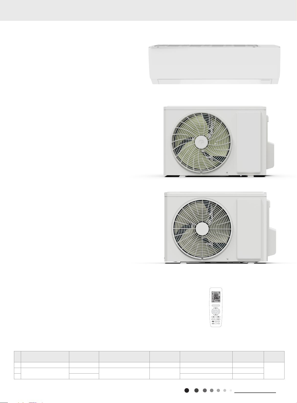
2. Specications
The above data is subject to change without notice. Please refer to the nameplate of the unit.
Outdoor
Unit
Outdoor Unit Model GWH09AGA-K6DNA1C/O GWH09AGA-K6DNA1C/O
Outdoor Unit Product Code CB385W05100 CB385W05101
Compressor Manufacturer ZHUHAI LANDA
COMPRESSOR CO.,LTD
ZHUHAI LANDA
COMPRESSOR CO.,LTD
Compressor Model QXF-N075zC170 QXF-N075zC170
Compressor Oil FW68DA or equivalent FW68DA or equivalent
Compressor Type Rotary Rotary
Compressor LRA. A / /
Compressor RLA A 3 3
Compressor Power Input W 633 633
Compressor Overload Protector / /
Throttling Method Capillary Capillary
Set Temperature Range ºC 16~30 16~30
Cooling Operation Ambient Temperature Range ºC 18~43 18~43
Heating Operation Ambient Temperature Range ºC -15~24 -15~24
Condenser Form Aluminum Fin-copper Tube Aluminum Fin-copper Tube
Condenser Pipe Diameter mm Φ7.94 Φ7.94
Condenser Rows-n Gap mm 1-1.2 1-1.2
Condenser Coil Length (LXDXW) mm 635X19.05X418 635X19.05X418
Fan Motor Speed rpm 940±20 940±20
Fan Motor Power Output W 20 20
Fan Motor RLA A 0.30 0.30
Fan Motor Capacitor μF 1.5 1.5
Outdoor Unit Air Flow Volume m3/h 1400 1400
Fan Type Axial-ow Axial-ow
Fan Diameter mm Φ350 Φ350
Defrosting Method Automatic Defrosting Automatic Defrosting
Climate Type T1 T1
Isolation I I
Moisture Protection IPX4 IPX4
Permissible Excessive Operating Pressure for
the Discharge Side MPa 4.3 4.3
Permissible Excessive Operating Pressure for
the Suction Side MPa 2.5 2.5
Sound Pressure Level (H/M/L) dB (A) 51/-/- 51/-/-
Sound Power Level (H/M/L) dB (A) 61/-/- 61/-/-
Dimension(WXHXD) mm 710X450X293 710X450X293
Dimension of Carton Box (LXWXH) mm 761X327X500 761X327X500
Dimension of Package(LXWXH) mm 764X330X525 764X330X525
Net Weight kg 21 21
Gross Weight kg 23 23
Refrigerant R32 R32
Refrigerant Charge kg 0.5 0.5
Connection
Pipe
Connection Pipe Length m 5 5
Connection Pipe Gas Additional Charge g/m 16 16
Outer Diameter Liquid Pipe inch 1/4 1/4
Outer Diameter Gas Pipe inch 3/8 3/8
Max Distance Height m 10 10
Max Distance Length m 15 15
Note: The connection pipe applies metric diameter.