Amada MG3 Hot Bar User manual

Original Instructions
76609576EN-MG3-HB-V1.0a
Digital Measuring Unit
MG3 Hot Bar
OPERATING INSTRUCTIONS

MG3 Hot Bar
76609576EN-MG3-HB-V1_0a.docx 2/49 2015-07-22
Annex:
-Safety Regulations
-General References on Resistance Welding
-Contact Addresses
Copyright 2015:
AMADA MIYACHI EUROPE GmbH
Lindberghstr. 1, 82178 Puchheim, Germany
All rights reserved. The products named in this manual are only used for identification
purposes and may be trademarks or registered trademarks of the respective companies
Version Date Revision notification
1.0 2013-04 New
1.0a 2015-10 Changed company name

MG3 Hot Bar
Table of Contents
76609576EN-MG3-HB-V1_0a.docx 3/49
Table of Contents
1General Information ........................................................................... 5
1.1Preface ........................................................................................................... 5
1.2Copyrights, Proprietary Rights........................................................................ 5
1.3Definition of Symbols Used ............................................................................. 6
1.3.1Prohibition and Warning Symbols...................................................................................6
1.3.2Further Symbols .............................................................................................................7
2Technical Description.......................................................................... 8
2.1Mode of Action................................................................................................ 8
2.2Technical Data ................................................................................................ 8
3Commissioning ................................................................................... 9
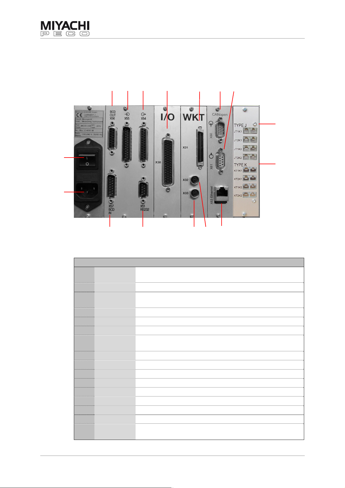
3.1Connecting the Components ......................................................................... 10
3.1.1Description of the Connectors.......................................................................................10
3.1.2Connector Pin Assignment of Inputs & Outputs ............................................................11
3.1.2.1Connector X54 (Outputs) ..................................................................................................11
3.1.2.2Connector X55 (Inputs) .................................................................................................... 12
3.1.2.3Connector X38 (I/O Outputs) ............................................................................................ 13
3.1.2.4Connector X38 (I/O Inputs)...............................................................................................14
3.1.2.5Connector X51 (RS232) / Baud rate ................................................................................... 14
3.1.2.6Connector X60 and X61 (CANopen).................................................................................... 15
3.1.3Connecting Temperature Sensor...................................................................................15
3.1.4Connecting Displacement Sensor (optional) .................................................................15
3.1.5Connecting Force or Pressure Sensor (optional)...........................................................15
3.1.6WK-Adapter (optional) .................................................................................................16
3.2Initial Commissioning................................................................................... 16
3.2.1Preconditions................................................................................................................16
3.2.2Starting-up ...................................................................................................................16
4Operation.......................................................................................... 17
4.1Toggle Wheel................................................................................................ 17
4.2LED Status Display........................................................................................ 18
4.3Screen (Display)........................................................................................... 18
4.3.1Display Windows – Quadrant 1 to 4 ..............................................................................19
4.3.2Menu Bar ......................................................................................................................19
4.3.3Program Display ...........................................................................................................19
4.3.4Measuring Mode............................................................................................................19
4.3.5Status Bar.....................................................................................................................19
4.4USB Port ....................................................................................................... 20
4.5UNDO Function ............................................................................................. 20
5How to …? ........................................................................................ 21
5.1Make General Settings .................................................................................. 21
5.2Measure Temperature................................................................................... 24
5.3Switch between Single and Multiple Measurement ....................................... 26
5.4Configure the Display Windows (Quadrants)................................................ 27
5.5Measure Displacement.................................................................................. 29
5.5.1Configure Displacement Measurement..........................................................................29
5.5.2Configure Part Detection...............................................................................................30

MG3 Hot Bar
Table of Contents
76609576EN-MG3-HB-V1_0a.docx 4/49
5.6Measure Pressure or Force ........................................................................... 32
5.7Set Limit Values............................................................................................ 33
5.8Copy, Save and Load Programs and Parameters ........................................... 34
5.9Count Measurements .................................................................................... 35
5.10View and Save Measuring Waveforms........................................................... 36
5.11Print Measured Values .................................................................................. 38
5.12Set and Change Password............................................................................. 39
5.13Configure the Logger .................................................................................... 40
5.14Display the Parameter Overview................................................................... 42
5.15Analyze Accept-Reject Ratio ......................................................................... 43
5.16Monitor Statistical Values ............................................................................. 44
5.17Determine Limit Values Statistically ............................................................. 45
5.18Transfer Data to PC/Laptop.......................................................................... 46
5.19Make a Screenshot of the Current Display .................................................... 46
5.20Register the Device....................................................................................... 46
6Integration in Automated Installations ............................................ 47
6.1Connection to field bus system ..................................................................... 47
7Appendix .......................................................................................... 48
7.1Error messages............................................................................................. 48
8Indexes ............................................................................................ 49
8.1Figures.......................................................................................................... 49
8.2Headwords.................................................................................................... 49

MG3 Hot Bar
General Information
76609576EN-MG3-HB-V1_0a.docx 5/49
1General Information
1.1 Preface
Information about safety regulations, usage location conditions,
copyrights, protection rights, symbols, and notes on resistance
welding can be found in the annex of the operating instructions.
Please read this information carefully before using this unit.
These operating instructions shall help you to familiarize yourself with the
unit and take advantage of its application possibilities when used as directed.
The operating instructions contain important notes to help operate the unit
safely, properly, and economically.
Observing the notes will help avoid risks, decrease repair costs and down
times, and enhance reliability and the service life of the unit.
The operating instructions should always be accessible at the unit operating
site. It should be read, understood and utilized by any person assigned to
work on or with the unit. This applies in particular to the notes on safety,
notes concerning safety regulations as well as safety and warning notes.
The fundamental principle applies:
Safety first!
Always carry out a function test before the first weld!
Warning
Do not operate the unit before reading these operating instructions!
1.2 Copyrights, Proprietary Rights
The copyright of these operating instructions remains the property of our
company.
These operating instructions are only meant for the internal use of the
operator of resistance welding units (hereafter called “unit”) and his/her
personnel.
It contains descriptions, technical drawings, regulations and instructions
which should not be copied, distributed, passed on to others or use without
permission for competitive purposes, whether completely or in part. In the
event of competitors endeavoring to see these operating instructions, we
expect the same fairness from you that you, in turn, would expect from your
customers in such cases.
All rights are reserved, particularly in cases of patent granting or other
registrations. We reserve the right to make technical alterations.

MG3 Hot Bar
General Information
76609576EN-MG3-HB-V1_0a.docx 6/49
1.3 Definition of Symbols Used
1.3.1 Prohibition and Warning Symbols
This symbol indicates an imminent danger.
Failure to heed these instructions will lead to irreversible or even life-
threatening injuries, grave adverse effects on health or considerable material
damage.
Danger
This symbol indicates a potentially imminent danger.
Failure to heed these instructions can lead to irreversible or even life-
threatening injuries, grave adverse effects on health or considerable material
damage.
Warning
This symbol warns of hazards emanating from electrical voltage.
Failure to heed these instructions can lead to grave, irreversible or even life-
threatening injuries caused by electric shocks.
Warning
This symbol indicates a potentially harmful situation.
Failure to heed these instructions can lead to product damage or damage to
objects in its near vicinity.
Caution
This symbol indicates possibly harmful situations.
Failure to heed these instructions can lead to work delays or light damage to
the product.
Attention
Crush hazard
Magnetic field hazard
Tipping over hazard
Prohibition for wearers of cardiac pacemakers
Prohibition for wearers of metallic implants

MG3 Hot Bar
General Information
76609576EN-MG3-HB-V1_0a.docx 7/49
1.3.2 Further Symbols
Wear eye protection
Disconnect power plug
Wear protection gloves
Pay attention to Operating Instructions
Information
This symbol indicates operator tips and other useful information for
optimum utilization of the machine.

MG3 Hot Bar
Technical Description
76609576EN-MG3-HB-V1_0a.docx 8/49
2Technical Description
2.1 Mode of Action
The MG3 Hot Bar is a digital measuring and monitoring instrument for Hot
Bar installations.
You can adjust up to 99 programs with different parameters for monitoring.
Choose one of these programs for monitoring the welding process.
The values of the last welds (up to 2500) are stored in a buffer.
If this buffer is full (or the set number of welds to be stored is reached), the
complete measurement data packet is written as a log file onto the USB-
stick.
You can print selected parameters of each welding on a printer with serial
interface.
Individual operator configurations remain stored even when the device has
been switched off.
The MG3 is operated by a toggle wheel.
2.2 Technical Data
Program monitoring 99 programs, internal or external program
selection
Measuring functions 2 temperatures with temperature peak,
temperature integral, temperature average,
temperature gradient, temperature difference,
heat time (s)
Optional: displacement and force or pressure
Counter Up and down counter with prewarn and final value
signal-output
Measuring range
temperature Temperature 1 (T1): 25 to 600 °C
Temperature 2 (T2): 25 to 600 °C
Measuring accuracy 1.5 % of upper range value for temperature
Graphic resolution Sample rate 100 ms
Measuring interval Variable
Note: The more graphics are displayed, data
through RS232 and limit values are monitored, the
longer the measuring interval.
Limit value setting Upper and lower limit value, independently from
each other
Prewarn setting Upper and lower prewarn value, independently
from each other
Graphic display VGA, 640 x 480 pixel
Optical indications 8 front LEDs
Inputs / outputs See chap. 3.1.1
Mains voltage and
frequency 110 - 240 Volt AC;
50-60 Hz, switching power supply
Power consumption 60 W
Ambient temperature 0 °C to 40 °C
Relative humidity max 70 %
Dimensions ½ 19“: (W x H x D) 280 x 140 x 340 mm
Weight approx. 5.4 kg, (approx. 11.9 lbs)

MG3 Hot Bar
Commissioning
76609576EN-MG3-HB-V1_0a.docx 9/49
3Commissioning
The MG3 Hot Bar is supplied with an adjustable support stand.
To have a non-dazzling reading of the screen adjust the tilt angle with this
stand.
Fig. 1: MG3 with support stand
Remove the MG3 Hot Bar from the packing and set it up at the designated
place.
Pull apart both caps at the stand’s pivot points and adjust the desired
position.

MG3 Hot Bar
Commissioning
76609576EN-MG3-HB-V1_0a.docx 10/49
3.1 Connecting the Components
3.1.1 Description of the Connectors
②
①
③④⑤ ⑥ ⑦ ⑧ ⑨
⑩
⑪
⑯⑮ ⑭ ⑬ ⑫
Fig. 2: Connectors on the housing rear side
No. Connector Function
①Mains Connector for mains cable.
Check mains voltage on type designation plate.
②On/off switch
③X56 Outputs for program number (set BCD or binary code
accordingly, 1...99)
④X55 Control inputs from peripheral equipment
⑤X54 Control outputs to peripheral equipment
⑥X38 Inputs and outputs extended I/O
⑦X31 Connector for displacement measuring or WK-Adapter
(for displacement and force or pressure measuring)
⑧X60 CANopen IN
⑨X61 CANopen Out
⑩TYPE J Connectors for thermocouples of thermode J
⑪TYPE K Connectors for thermocouples of thermode K
⑫X63 Ethernet
⑬X32 Not used
⑭X33 Not used
⑮X51 RS232 interface (e.g. to serial printer)
⑯X57 Inputs for program number (set BCD or binary code
accordingly, 1...99)

MG3 Hot Bar
Commissioning
76609576EN-MG3-HB-V1_0a.docx 11/49
3.1.2 Connector Pin Assignment of Inputs & Outputs
The outputs always represent the last measurement.
They will be set or cleared only after a new measurement.
In the following tables means
High = voltage level +24 V and Low = voltage level 0 V
3.1.2.1 Connector X54 (Outputs)
Pin Name Chan. Function
1 Ready 1 and 2 Control unit ready to receive data. Ready flag
does not apply during counter or measured value
reset, during boot procedure or by HIGH signal at
control input NOT READY, measurement reset,
data transfer
2 Temperature 1 Signalizes the superior control that measurement
is started by an external trigger signal. Signal
remains until manually set measuring time ends.
3 WARN min. 1 and 2 Monitoring of minimum prewarn value.
4 WARN max. 1 and 2 Monitoring of maximum prewarn value.
5 Limit value
min. 1 and 2 Monitoring of minimum limit value.
6 Counter limit 1 and 2 Signal waiting when counter reached final value,
until counter reset.
7 REJECT 2 Signal waiting as soon as monitored parameter is
out of limits.
8 Temperature 2 Signalizes the superior control that measurement
is started by an external trigger signal. Signal
remains until manually set measuring time ends.
14 ACCEPT 1 Signal waiting as long as parameters monitored
with limit values are within the limit.
15 REJECT 1 Signal waiting as soon as monitored parameter is
out of limits.
16 Overflow 1 and 2 Signal waiting if a set measuring range is
exceeded by the measured parameter.
17 No
temperature 1 Signal is activated (High):
a) after external trigger signal if no temperature
is measured during this.
b) after valid part detection
c) if trigger source “0 penetration“ or “Force
trigger“ is activated and no temperature is
measured.
Signal is deactivated (low):
a) at beginning of measurement
b) with signal at input reset measuring value
18 Limit value
max. 1 and 2 Monitoring of maximum limit value.
19 Counter WARN 1 and 2 Signal waiting when counter reached prewarn
value, until counter reset.
20 ACCEPT 2 Signal waiting as long as parameters monitored
with limit values are within the limits.

MG3 Hot Bar
Commissioning
76609576EN-MG3-HB-V1_0a.docx 12/49
Pin Name Chan. Function
21 No
temperature 2 Signal is activated (High):
a) after external trigger signal if no temperature
is measured during this.
b) after valid part detection
c) if trigger source “0 penetration“ or “Force
trigger“ is activated and no temperature is
measured.
Signal is deactivated (low):
a) at beginning of measurement
b) with signal at input reset measuring value
3.1.2.2 Connector X55 (Inputs)
Pin Name Chan. Function
5 Clear ACCEPT
outputs, set
faults
1 and 2 Disables all ACCEPT outputs;
all limit, REJECT and prewarn (WARN) outputs
(fault outputs) are set.
8 Save log-file 2
9 Counter reset 1 Resets counter to its initial value.
10 Measurement
reset and
outputs cleared
2 Displayed measured values are set to zero and
outputs are cleared.
12 Hold 1 High: measured values of a succeeding welding
are not accepted. With falling edge measured
values are read in again starting with a new
welding.
13 Trigger 1 High:
- if no measuring signal is detected a ‘no
temperature error’ is set with falling edge.
- only the last measuring before falling edge is
evaluated.
17 Not ready 1 and 2 Disables parameter value acquisition; ready
output at X54 pin 1 goes to LOW.
18 Set ACCEPT
outputs, clear
faults
1 and 2 Disables all REJECT and limit value outputs; all
ACCEPT outputs are set.
21 Save log-file 1
22 Counter reset 2 Resets counter to its initial value.
23 Measurement
reset and
outputs
cleared.
1 Displayed measured values are set to zero and
outputs are cleared.
24 Hold 2 High: measured values of a succeeding welding
are not accepted. With falling edge measured
values are read in again starting with a new
welding.
25 Trigger 2 High:
- if no measuring signal is detected a ‘no
temperature error’ is set with falling edge.
- only the last measuring before falling edge is
evaluated.

MG3 Hot Bar
Commissioning
76609576EN-MG3-HB-V1_0a.docx 13/49
3.1.2.3 Connector X38 (I/O Outputs)
Pin Name Chan. Function
3
4 Displacement min.
Displacement max. 1
1 High: currently measured displacement
is outside the set limits
5
6 Displacement min.
Displacement max. 2
2 High: currently measured displacement
is outside the set limits
7
8 Prewarn Dist. S3
Prewarn Dist. S6 1
2 High: prewarn value is exceeded
9
10 Sinking 2 Accept 2
Sinking 1 Accept 1 2
1 Output enabled if sinking 2/1 is ACCEPT
11 Pressure/Force
reject 1
12 Pressure/Force
accept 1
13 Pressure/Force
reject 2
14 Pressure/Force
accept 2
17
31
Path Abort
Temperature High
Path Abort
Temperature Low
2
2
High: cutoff value is exceeded.
Low: cutoff value is exceeded.
18,
21 Plus terminal (+) Common plus terminal (+) for PIN:
14, 13, 11, 12, 10, 9, 8, 7, 6, 5, 4, 3,
30, 29, 28, 27, 26, 25, 24, 23
19 Common (+) 1 1 Common plus terminal 10 – 30 V for PIN
16 and 20.
20
16
Path Abort
Temperature High
Path Abort
Temperature Low
1
1
High: cutoff value is exceeded.
Low: cutoff value is exceeded.
25
26
Parts Detection
Low active
Parts Detection
Low active
1
2
Low: limit values are not reached or
exceeded, (pressure switch control unit).
27
28
Path Parts
Detection min.
Path Parts
Detection max.
1
1
Depending on setup default; becomes
active if the currently measured parts
control path min./max. is exceeded or
remains under.
29
30
Path Parts
Detection min.
Path Parts
Detection max.
2
2
High: currently measured parts detection
path min/max is exceeded or remains
under.
34 Common (+) 2 Common plus terminal 10 – 30 V for PIN
17 and 34.

MG3 Hot Bar
Commissioning
76609576EN-MG3-HB-V1_0a.docx 14/49
3.1.2.4 Connector X38 (I/O Inputs)
Pin Name Chan. Function
22 Ground
connection Common connection of the inputs.
35 n/c
36 n/c
37 n/c
38 n/c
39 Reference run
part detection 1 and 2 High: part detection without inserted part
for reference run
(can also be actuated with the reference
button on the display)
41 n/c
42 n/c
43 n/c
44 n/c
45 Null Sinking 2 Triggers with rising edge, cooling time
with falling edge.
46 Null Sinking 1 Triggers with rising edge, cooling time
with falling edge.
47 Parts Detection 2 Set parts detection = HWScan.
Measured value is evaluated and part min.
2 – max. 2 is set.
48 Parts Detection 1 Set parts detection = HWScan.
Measured value is evaluated and part min.
1 – max. 1 is set.
49 Start Measure 2 Starts part detection 2 for sensor 2.
50 Start Measure 1 Starts part detection 1 for sensor 1.
3.1.2.5 Connector X51 (RS232) / Baud rate
Pin Name Pin Name
1 free 6 free
2 TxD 7 CTS
3 RxD 8 RTS
4 5V 9 free
5 GND
Baud rates (bit/s) 9600; 19200; 38400; 57600; 115200
Data bits 8
Start bits 1
Stop bits 1
Parity none
Busy Control no/off

MG3 Hot Bar
Commissioning
76609576EN-MG3-HB-V1_0a.docx 15/49
3.1.2.6 Connector X60 and X61 (CANopen)
Connection with standard RS232 extension cable (1:1)
Pin Name Function
1 Free
2 CAN_L Low-level
3 CAN_GND Ground
4 Free
5 CAN_SHLD Circuit shield
6 Free
7 CAN_H High-level
8
9
CAN-Baud rates 1 MB/s; 800 kB/s; 500 kB/s; 250 kB/s; 125 kB/s;
50 kB/s; 20 kB/s; 10 kB/s
3.1.3 Connecting Temperature Sensor
For the mounting of the thermocouples on the Hot Bar head please see the
operating instructions of the Hot Bar system.
Connect the plug of the thermocouples with the corresponding socket on the
rear side of the MG3 (see chap. 3.1.1).
Note: Switch off the MG3 Hot Bar before connecting.
3.1.4 Connecting Displacement Sensor (optional)
For displacement measurement you need an optional available displacement
sensor and the corresponding mounting kit.
For the mounting of the displacement sensor on the Hot Bar head please see
the operating instructions of the Hot Bar system.
Connect the plug of the displacement sensor with the supplied sensor cable
adapter and then connect the adapter with the corresponding socket (X31)
on the rear side of the MG3 (see chap. 3.1.1).
Note: Switch off the MG3 Hot Bar before connecting.
If a WK-adapter is used (necessary for force or pressure measurement),
connect the plug of the displacement sensor directly to the WK-adapter.
3.1.5 Connecting Force or Pressure Sensor (optional)
For force or pressure measurement you need optional available force or
pressure sensor, the corresponding mounting kit and the WK-adapter.
For the mounting of the respective sensor on the Hot Bar head please see the
operating instructions of the Hot Bar system.
Connect the plug of the sensor to the WK-adapter and then connect the
adapter with the corresponding socket (X31) on the rear side of the MG3 (see
chap. 3.1.1).
Note: Switch off the MG3 Hot Bar before connecting.

MG3 Hot Bar
Commissioning
76609576EN-MG3-HB-V1_0a.docx 16/49
3.1.6 WK-Adapter (optional)
Fig. 3: WK-Adapter
For force or pressure measurement you need an optional available force or
pressure sensor, the corresponding mounting kit and the WK-adapter.
For the mounting of the respective sensor on the Hot Bar head please see the
operating instructions of the Hot Bar system.
Connect the plug of the sensor to the WK-adapter and then connect the
adapter with the corresponding socket (X31) on the rear side of the MG3 (see
chap. 3.1.1).
Note: Switch off the MG3 Hot Bar before connecting.
3.2 Initial Commissioning
3.2.1 Preconditions
•Check whether the MG3 Hot Bar is switched off. The main switch must be
in position 0.
See chap. 3.1.1.
•Check mains voltage and frequency at place of installation. See chap. 2.2.
•Plug in power supply cord to the corresponding connector at the rear of
the MG3 Hot Bar.
•Check whether the USB stick is plugged in.
3.2.2 Starting-up
Switch on the main switch on the rear side of the MG3 Hot Bar.
After initialization - lasting for approx. 30 seconds - you can configure the
MG3 Hot Bar.

MG3 Hot Bar
Operation
76609576EN-MG3-HB-V1_0a.docx 17/49
4Operation
Fig. 4: Control panel MG3 Hot Bar
4.1 Toggle Wheel
The toggle wheel is the central operating element of the MG3 Hot Bar.
You can carry out all settings with the toggle wheel:
•Select by turning the toggle wheel. The selected item changes to red.
•By pushing the toggle wheel (hereinafter called clicking) you can enable
resp. activate/deactivate the selected item (button, check box, list box,
quadrant, etc.).
•Grayed items are disabled and cannot be selected.
Input fields are:
•Buttons which trigger a certain action when clicked
•Check boxes which have two switching conditions (black = on/active;
gray = off/inactive)
•List boxes which allow you to select from a list of options.
•Edit boxes which allow the input of numbers.
Click once to get to the quick-edit mode where you can change the whole
number (by turning the toggle wheel).
Click twice to get to the precision editing mode where you can change
each digit separately.
Click again to get back to the edit box.
USB-Port
Screenshot
Remove USB-Stick
Toggle Wheel
Screen (display)
LED
status
display

MG3 Hot Bar
Operation
76609576EN-MG3-HB-V1_0a.docx 18/49
4.2 LED Status Display
READY MG3 Hot Bar ready for measurement
TRIGGER1 Measurement activity on channel 1
TRIGGER2 Measurement activity on channel 2
OVERFLOW MG3 Hot Bar overflow measuring range
ACCEPT Measurement within set limits
PREWARN Measurement outside set prewarn limits
REJECT t
Measurement outside set limits
USB USB stick missing (blinking) or access to USB stick
(on steady)
4.3 Screen (Display)
Fig. 5: Screen (Display)
1. Display window quadrant 1 (Q1)
2. Display window quadrant 2 (Q2)
3. Menu bar
4. Program number selection
5. Button for single measurement
(SINGLE)
6. Button for permanent
measurement (RUN)
7. Button for logging (LOGGER)
8. Button for configuration menu
(MENU)
9. Button for parameter
overview (PARAM)
10.Button for analysis
(LIMITS)
11.Shows current measuring
mode
(SINGLE/RUN)
12.Status bar for status, help
and fault messages
13.Display window quadrant 4
(Q4)
14.Display window quadrant 3
(Q3)

MG3 Hot Bar
Operation
76609576EN-MG3-HB-V1_0a.docx 19/49
4.3.1 Display Windows – Quadrant 1 to 4
The measured values can be shown in four fully configurable display windows
(quadrants).
Each quadrant can show the values in one of the following display modes:
•numeric
•graphical
•SPC*-Chart
•SPC*-Values
* SPC: Statistical Process Control
Select the quadrant by turning the toggle wheel.
Click on one quadrant to see an enlarged and more detailed view of this
quadrant with additional setting possibilities.
To get back to the previous display click to the main display field in this
screen.
Special feature of the numeric display mode:
After a measurement the measured value can flash colored or gray.
This means:
•yellow: the measured value is outside the set prewarn limits
•red: the measured value is outside the set limits
•gray: invalid measurement (range overflow)
4.3.2 Menu Bar
The menu bar comprises the following controls:
•Display/setting of the current program number (1…99)
•Display of the current measuring mode (SINGLE/RUN)
•Buttons for selecting displays and measuring mode
4.3.3 Program Display
Shows the number of the currently active measuring program.
Range: 1 to 99.
Program selection by the toggle wheel.
4.3.4 Measuring Mode
You can switch between the two measuring modes by clicking on it:
•Single measurement (SINGLE) or
•Multiple measurement (RUN)
The currently active measuring mode is shown in the last field below.
4.3.5 Status Bar
Depending on the selected controls the status bar shows:
•Information on the last measurement (channel 1/2)
•Details on the meaning of the selected controls
•Information on the condition of the selected function
•Fault messages

MG3 Hot Bar
Operation
76609576EN-MG3-HB-V1_0a.docx 20/49
4.4 USB Port
Loss of data !
Disable the USB stick before you remove it from the notebook or PC.
Press the ‘remove USB stick’ button on the front of the MG3 Hot Bar before
you remove the USB stick (see chap.4, fig. 4).
Caution
4.5 UNDO Function
The menu bar offers the button UNDO for all screens where parameters can
be set or changed.
With this button you can undo the last (up to 50) settings in this screen one
by one.
Table of contents
Other Amada Measuring Instrument manuals
Popular Measuring Instrument manuals by other brands

LaserLiner
LaserLiner BeamControl-Master BCM operating instructions

Spectra Geospatial
Spectra Geospatial Focus 35 user guide

Autel
Autel TBE200E manual

Sper scientific
Sper scientific 800098 instruction manual

Dwyer Instruments
Dwyer Instruments 250-AF Series Installation and operating instructions

pH ELECTRODE
pH ELECTRODE PE-03 Operation manual

TESTO
TESTO 521 instruction manual

Vanguard Instruments
Vanguard Instruments Auto-Ohm 10 user manual

LaserLiner
LaserLiner MeterMaster Plus quick start guide

Decagon Devices
Decagon Devices KD2 Pro Operator's manual

MRC
MRC PS-9302 instruction manual

Blue Sea Systems
Blue Sea Systems M2 OLED Quick start installation guide