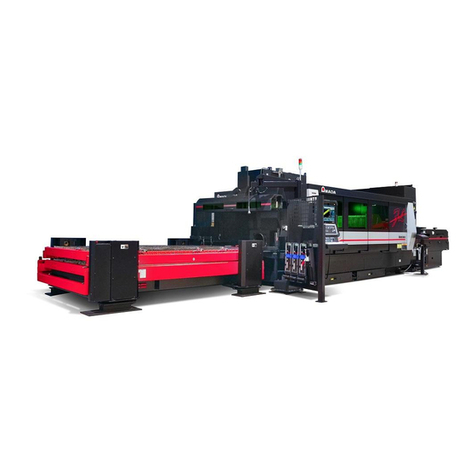
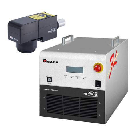
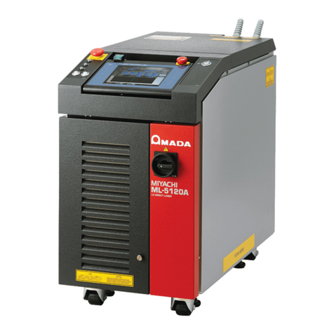
Amada ML-9011A User manual

Z06OM1191383-06
YVO4SHG Laser Marker
ML-9011A
OPERATION MANUAL

Thank you for purchasing our YVO4SHG laser marker ML-9011A.
Please read this manual carefully to ensure correct use of the product. Store the manual in a
convenient place for future reference.
This documentation for the YVO4SHG laser marker ML-9011A covers installation, operation,
maintenance, and specifications.
For marking in LMDraw6 using a computer, refer to the manual for LMDraw6.
■Notes
•Unauthorized reproduction of this manual in whole or in part is prohibited.
•The contents of this manual are subject to change without notice.
•Every effort has been made to ensure the accuracy of this manual, but if you notice oversights or
errors, please notify your dealer.
•Be sure to read the user's manuals for any equipment used in conjunction with the system (e.g.,
documentation for computer systems).
•This system incorporates a QR code engine developed by Denso Wave Inc.
•Graphics rendering support in LMDraw6 (for importing DXF data) is provided by CADBuilderOCX,
developed by Knack SoftWare Inc.
■Trademarks
•Microsoft, Windows, and OpenType are trademarks or registered trademarks of Microsoft
Corporation in the United States and other countries.
•AutoCAD is a trademark or registered trademark of Autodesk Incorporated in the United States
and other countries.
•TrueType is a trademark or registered trademark of Apple Incorporated in the United States and
other countries.
•Intel and Celeron are trademarks or registered trademarks of Intel Corporation or its subsidiaries
in the United States and other countries.
•Other company and product names in this manual are trademarks or registered trademarks of
their respective owners.
■Symbols Used in This Manual
•Menus, icons, buttons, windows, tabs, and keys are indicated in brackets ([ ]).
Example: Click the [OK] button.
•Cross-references are enclosed in quotations.
Example: See 3.2.1 "Marking Condition Settings" (p. 5).
Indicates instructions that must be followed to prevent hardware or software damage or
operating errors.
Indicates that incorrect operation may pose a risk of injury or damage.
Indicates additional information on a particular topic.

Chapter Overview
Chapter 1 Safety Precautions
Precautions for safe use of the marker
Chapter 2
Overview of the ML-9011A
Summary of fiber laser marker features
Chapter 3 Part Names and Functions
Marker part names and functions
Chapter 4 System Configuration
System configuration, constituent parts, and included accessories
Chapter 5 Unpacking
Size and mass of the marker packaging, as well as lists of package contents
Chapter 6 Installation
Marker installation requirements and instructions
Chapter 7 Starting/Stopping the Equipment
Part names, starting and stopping the equipment, and general safety precautions
Chapter 8 Marker Specifications
Detailed marker specifications
Chapter 9 Serial Interface Specifications
RS-232C communication specifications for the marker
Chapter 10
QR Code and DataMatrix Specifications
QR code and DataMatrix specifications and instructions for preparing data elements
Chapter 11 Interface Specifications
General marker interface specifications
Chapter 12 Maintenance
Marker maintenance information and instructions
Chapter
6
Chapter
1
Chapter
2
Chapter
3
Chapter
4
Chapter
5
Chapter
7
Chapter
8
Chapter
9
Chapter
10
Chapter
11
Chapter
12


1
ML-9011A
Contents
■Notes
■Trademarks
■Symbols Used in This Manual
Chapter Overview
Chapter 1
Safety Precautions...............................................................5
1.1 Meaning of Symbols.......................................................................6
1.2 Danger, Warning, and Caution Items.............................................7
1.3 Guidelines for Normal Use...........................................................10
1.4 For Disposal.................................................................................12
1.5 Warning/Explanation Labels for Safety........................................13
■Control Unit ..................................................................................................13
■Head Unit .....................................................................................................13
1.6 LD (Diode Laser) Precautions......................................................14
Chapter 2
Overview of the ML-9011A.................................................15
2.1 Features.......................................................................................15
■YVO4 SHG Laser Marking ...........................................................................15
■ML-9011A.....................................................................................................15
Chapter 3
Part Names and Functions................................................17
3.1 Control Unit ..................................................................................17
■Front.............................................................................................................17
■Back .............................................................................................................19
3.2 Head Unit .....................................................................................21
■Side ..............................................................................................................21
■Top ...............................................................................................................21
■Back .............................................................................................................22
Chapter 4
System Configuration........................................................23
4.1 System Configuration Schematic.................................................23
4.2 Components.................................................................................24
4.3 Included Accessories ...................................................................24
4.4 Options.........................................................................................25
Chapter 5
Unpacking...........................................................................26
5.1 Moving the Container...................................................................26
■Container Size and Mass ............................................................................. 26

2ML-9011A
Contents
5.2 Checking the Container Contents ................................................27
■Containers....................................................................................................27
■Options.........................................................................................................28
Chapter 6
Installation ..........................................................................29
6.1 Installation Requirements.............................................................29
■Control Unit ..................................................................................................29
■Head Unit .....................................................................................................30
6.2 Connections .................................................................................32
Chapter 7
Starting/Stopping the Equipment .....................................33
7.1 Turning the Hardware On and Off................................................33
■Starting the Marker.......................................................................................33
■Stopping the Marker.....................................................................................37
7.2 Adjusting the Work Distance........................................................38
Chapter 8
Marker Specifications ........................................................40
8.1 Basic Specifications .....................................................................40
8.2 Marking Area Specifications.........................................................42
8.3 External Specifications.................................................................43
■Control Unit ..................................................................................................43
■Head Unit (Analog Scanner Specification) ...................................................44
■Head Unit (Digital Scanner Specification (Option)) ......................................45
Chapter 9
Serial Interface Specifications ..........................................46
9.1 Cable Specifications.....................................................................46
■Pin assignments (unit side) ..........................................................................46
■Connection example: Connected to a computer ..........................................47
9.2 Communication Settings ..............................................................48
9.3 Communication Codes.................................................................49
9.4 Communications Protocol ............................................................50
■Transmission control code ...........................................................................50
■Checksum ....................................................................................................50
■Numerical notation .......................................................................................51
■String notation ..............................................................................................51
9.5 Commands...................................................................................52
■Command Details.........................................................................................53
9.6 Communication Period.................................................................67
Chapter 10
QR Code and DataMatrix Specifications..........................68
10.1 QR Code Specifications...............................................................68
10.1.1 QR Code Symbol Specifications.......................................68
■Detailed Specifications.................................................................................69

3
Contents
ML-9011A
10.1.2 Preparing Data..................................................................70
■Overview of Sample Data............................................................................. 70
■Examples of Preparing Data Elements ........................................................71
10.2 DataMatrix Specifications.............................................................74
10.2.1 DataMatrix Symbol Specifications.....................................74
■Detailed Specifications.................................................................................74
10.2.2 Preparing Data..................................................................75
■Overview of Sample Data............................................................................. 75
■Examples of Preparing Data Elements ........................................................76
Chapter 11
Interface Specifications.....................................................79
11.1 External Input and Output (EXT. I/O)...........................................80
11.1.1 Input and Output Signals...................................................80
■Input Signals.................................................................................................80
■Output Signals..............................................................................................81
11.1.2 Connection Examples .......................................................82
■When connected to an output PLC with a 24 V DC source..........................82
■When using a contact signal ........................................................................83
■When using an open-collector signal ...........................................................84
11.1.3 Time Chart ........................................................................85
■During normal operations (no EEXT. I/O) ....................................................85
■If laser errors occur ......................................................................................86
■If data errors occur .......................................................................................87
■When marking is stopped............................................................................. 87
■If the power is turned ON and OFF ..............................................................88
■If the counter is used (Count reset and count up enabled) ..........................89
■When counter stop is used (increment of 1).................................................90
■When carriage control signal is used ...........................................................91
11.2 Extended External Input and Output (EEXT. I/O) ........................92
11.2.1 Input and Output Signals...................................................92
■Input Signals.................................................................................................92
■Output Signals..............................................................................................92
11.2.2 Connection Examples .......................................................93
■When connected to an output PLC with a 24 V DC source..........................93
■When using a contact signal ........................................................................94
■When using an open-collector signal ...........................................................95
11.2.3 Time Chart ........................................................................96
■During normal operations.............................................................................96
■During data errors (errors from unregistered layouts)..................................97
11.3 Emergency Stop/
Remote Interlock (REM. I/L)98
11.3.1 Pin Layout .........................................................................99
■Input Signals.................................................................................................99
■Output Signals..............................................................................................99
11.3.2 Connection Examples .....................................................100
■Remote Interlock ........................................................................................100
■Emergency Stop.........................................................................................101

4ML-9011A
Contents
11.3.3 Time Chart ......................................................................103
■Remote Interlock ........................................................................................103
■Emergency Stop.........................................................................................104
Chapter 12
Maintenance......................................................................105
12.1 Maintenance Tasks....................................................................105
12.2 Part Replacement Schedule ......................................................106
12.3 Air Filter Inspection and Replacement .......................................108
12.3.1 Control Unit .....................................................................108
12.3.2 Head Unit ........................................................................109
12.4 Protective Glass Inspection and Replacement ..........................110
12.4.1 Cleaning the Protective Glass.........................................110
12.4.2 Replacing the Protective Glass.......................................110
12.5 FC-LD Inspection and Replacement..........................................112
■FC-LD Warranty Period.............................................................................. 112
12.6 Desiccant Agent Inspection and Replacement ..........................113
12.7 Backup Lithium Battery Replacement........................................116
12.8 Memory Card Management .......................................................118
■How to Remove the Memory Card .............................................................118
■How to Insert the Memory Card .................................................................118
■Memory Card Backup.................................................................................119
■Restoring Backup Data ..............................................................................119
Index ......................................................................................... 120

5
ML-9011A
Safety Precautions
Before using the Laser Marker, carefully read these safety precautions to ensure correct use.
•These precautions are intended to ensure safe use of the unit and to prevent damage or personal
injury to the user and other individuals. Be sure to read all precautions; they are critical for ensuring
safe use.
•The warning symbols are defined as follows:
Incorrect operation poses imminent risk of serious injury or fatality.
Incorrect operation may pose risk of serious injury or fatality
Incorrect operation may pose risk of injury or damage.
DANGER
WARNING
CAUTION
Chapter
1

Chapter
1
6ML-9011A
Chapter 1Safety Precautions
1.1 Meaning of Symbols
These symbols indicate prohibited actions.
The symbols warn against actions that will void the terms of the warranty.
The prohibited action is depicted in a circle or illustrated in a figure or described in a statement nearby.
These symbols indicate actions users must take.
The prohibited action is depicted in a circle or illustrated in a figure or described in a statement nearby.
The symbol indicates caution for electrical shock.
The symbols indicate danger, warning, or caution items.
The prohibited action is depicted in a circle or illustrated in a figure or described in a statement nearby.

Chapter
1
7
ML-9011A
1.2 Danger, Warning, and Caution Items
Do not touch inside the Laser Marker when it is switched on
Doing so may result in electric shock.
Never attempt to disassemble, repair, or modify the Laser
Marker
Doing so may result in electric shock or fire.
Refrain from any mechanical adjustment other, than
maintenance specifically described in the operation manual.
Never expose eyes or skin to laser irradiation
Exposure to direct or scattered laser light is extremely
hazardous.
Direct exposure of the eye to laser beams may result in
blindness.
Never burn, destroy, cut, crush or chemically decompose
the Laser Marker
This product incorporates parts containing gallium arsenide
(GaAs).
DANGER

Chapter
1
8ML-9011A
Chapter 1Safety Precautions
Wear protective eyewear
Always wear protective eyewear having an optical density of at
least 7 when using the Laser Marker.
Keep in mind that exposure of the eyes to direct laser
irradiation through protective eyewear may result in blindness,
even when wearing protective eyewear. Protective eyewear
attenuates the laser beam, but does not block it.
Never aim the laser at any parts of your own body or those
of other individuals
Exposure to laser beams will cause severe burns.
Never aim the laser at yourself or at anyone else.
Do not touch workpieces during or just after marking
Workpieces may still be very hot.
Use only the specified cables. Make sure they are firmly
connected
Using cables of inadequate current capacity or connecting
cables loosely may result in fire or electric shock.
Avoid damaging power or connecting cables
Do not step on, twist, or pull cables.
Damaged cables may result in electric shock, short circuits, or
fires.
To repair or replace cables, contact your dealer or us.
Stop using the Laser Marker if any problems arise
Continuing to use the Laser Marker in the presence of
abnormalities (fumes, unusual sounds, excessive heat, smoke,
and so forth) may result in electric shock or fire.
In this case, immediately turn OFF the Laser Marker and
contact your dealer or us.
Ground the Laser Marker
Make sure that the Laser Marker is grounded before turning ON
the power supply. Failure to ground the Laser Marker may
result in electric shock.
Pacemaker users must not approach the Laser Marker
Unless a physician has consented, pacemaker users must not
approach the Laser Marker in use, or even approach the
working area.
The Laser Marker generates electromagnetic fields that may
affect pacemaker function.
WARNING

Chapter
1
9
ML-9011A
1.2 Danger, Warning, and Caution Items
Avoid spilling or splashing water on the Laser Marker
The presence of water on electrical parts may result in electric
shock or short circuits.
Use the appropriate tools to terminate the power cable (wire
strippers, crimp tools, etc.)
Failure to use the appropriate tools may result in damage to the
wire core, resulting in fire or electric shock.
Install the Laser Marker on a solid, level surface
Should the Laser Marker tip over or fall, injury or damage to the
unit may result.
Never place liquid containers on the Laser Marker
Liquid spills may degrade the unit's insulation, resulting in
electric leaks or fire.
Keep combustible materials away from the Laser Marker
Sparks or spattering material may ignite combustible matter.
Do not apply the laser beam to combustible materials
To avoid risk of fire, never apply the laser beam to flammable or
combustible materials.
During use, do not cover the Laser Marker with a blanket,
cloth, or similar articles
When using the Laser Marker, do not cover with a blanket,
cloth, or similar articles.
The Laser Marker may become extremely hot, resulting in fire.
Do not use the Laser Marker for any purpose other than
laser marking
Using the unit for nonspecified applications may result in
electric shock or fire.
Wear protective gear
Use protective gloves, long-sleeve garments, leather aprons, or
other appropriate protective gear.
Sparks or spattering material may burn the skin on contact.
Keep a fire extinguisher nearby
Keep a fire extinguisher in the marking area in case of fire.
Maintain and inspect the unit at periodic intervals
Maintain and inspect the unit at periodic intervals. Repair any
damage before resuming use.
CAUTION

Chapter
1
10 ML-9011A
Chapter 1Safety Precautions
•Appoint a safety supervisor with as much expertise and experience with lasers and laser
equipment as possible. The supervisor, who will be in charge of the laser key switch, should
familiarize users with safety issues and coordinate laser marking.
•Partition off the area which might be exposed to the laser beam. A supervisor should control this
work area and post signs to keep out unauthorized personnel.
•Install the Laser Marker on a solid, level surface. Using the unit (other than the Head Unit) at an
angle or on its side may damage it.
-
To prevent distorted marking, put workpieces on the same stand as the Head Unit so that
the workpieces do not vibrate during marking.
-
The required power supply is as follows: single-phase 100 V AC to 120 V AC (50/60 Hz)
with a capacity of at least 15 A, or 200 V AC to 240 V AC (50/60 Hz) with a capacity of at
least 7 A.
-
Be sure to ground the unit with a Class D ground.
•To ensure optimal marking quality, use the Laser Marker in a place where the ambient
temperature is 5 to 35 °C, where the relative humidity is 40 to 80%, and where it is not subject to
sudden temperature fluctuations. In addition, do not use the marker in the following places:
-
Where there is excessive dirt, dust, or oil mist
-
Where the unit is subject to vibration or impact
-
Where the unit is exposed to chemicals
-
Where there is a nearby source of high noise
-
Where moisture may condense on the unit
•If the room temperature changes quickly (such as when a heater is turned on in cold weather),
moisture may condense on the optical elements. Dust may adhere or the elements may become
fogged up with condensation. Thus, avoid sudden temperature changes. If condensation has
occurred, wait for a while after turning the unit on before starting operation.
•The exterior of the system should be wiped clean using a soft or moist cloth. If the exterior is
particularly dirty, wipe it clean using diluted detergent or alcohol.
Do not use paint thinner, benzine, or similar chemicals, which may discolor the unit or deform
parts.
•Do not place screws or other foreign objects inside the marker. This may damage the unit.
•Operate the switches and buttons gently by hand. Applying excessive force or using the tip of a
screwdriver, a pen, or other instrument may damage or break the switches or buttons.
•Operate only one switch or button at a time. Operating several switches or buttons at a time may
damage or break the unit.
•If a computer is connected, it will continue to access the memory card for about 15 seconds after
going offline. During this time, do not turn off the MAIN POWER switch of the Control Unit.
1.3 Guidelines for Normal Use

Chapter
1
11
ML-9011A
1.3 Guidelines for Normal Use
•If a computer is connected, never disconnect the LAN cable before turning off the MAIN POWER
switch.
•For more consistent marking, allow the unit to warm up for about 10 to 30 minutes after turning
on the LD. The warmup time varies depending on the temperature and workpiece material.
•In the LD starting state, you will see green light even when the laser is not emitted. Since it is
classified Class 1 or lower, it does not have a safety problem, but do not directly look it in.
•When a supervisor or operator enters the area where the laser is used, safety measures not to
exceed the MPE* level must be provided.
* MPE: The maximum level of permissible exposure of the eyes or skin to laser beams.
Abbreviation of Maximum Permissible Exposure.
•Since the surge absorber is built in, do not perform the insulation resistance test and the
withstand voltage test. If the surge absorber fails, the marker may become unusable.
For other information on managing laser equipment or the MPE level, refer to the
following standards.
・JIS C 6802 "Safety of laser products"
・Ministry of Health, Labour and Welfare Notification No. 0325002 "Prevention
measures against laser injuries" (in Japanese)

Chapter
1
12 ML-9011A
Chapter 1Safety Precautions
This product incorporates parts containing gallium arsenide (GaAs). At the time of disposal, separate it
from general industrial waste or domestic waste and carry out the disposal in accordance with
applicable laws and regulations.
1.4 For Disposal

Chapter
1
13
ML-9011A
1.5 Warning/Explanation Labels for Safety
The following labels are applied to the marker. Read and follow the instructions on the labels to ensure
correct use.
■Control Unit
■Head Unit
1.5 Warning/Explanation Labels for Safety
%#76+10
ᵈᗧ
%.'#06*'#+4(+.6'4
10%'#/106*
ࠛࠕࡈࠖ࡞࠲ߪᲤ
ߒߡߊߛߐޕ
ࡈࠔࠗࡃߩᦛߍඨᓘߪOOએ
⏕ߒߡߊߛߐޕ
'0574'6*'$'0&+0)4#&+75
1((+$'4OO14/14'
ᵈᗧ
%#76+10
ߎߎࠍ㐿߈ޔࠗࡦ࠲ࡠ࠶ࠢࠍ⸃㒰
ᵈᗧ
ߔࠆߣࠢࠬߩࠩ߇ࠆ
ࡆࡓ߿ᢔశߩ⋡ߪ
⊹⤏߳ߩⵍߪෂ㒾㧍
ߚࠅ⸅ࠇߚࠅߒߥߎߣ
%.#55.#5'44#&+#6+10
%#76+10
9*'012'0#0&+06'4.1%-5
&'('#6'Q+&';'
145-+0':21574'61&+4'%6
145%#66'4'&4#&+#6+10
ࡈࠔࠗࡃߪࠤࡉ࡞ࠍឞࠎߢ
ⵝ⟎ࠍᜬߜㆇ߮ߒߥߎߣޕ
&1016%#44;6*'&'8+%'
$;(+$'414%#$.'
ᵈᗧ
%#76+10
ߎߩ㕙߆ࠄOOએߩ
ࠬࡍࠬࠍ⏕ߒߡߊߛߐ
#..19#6.'#56OO
%.'#4#0%'106*+55+&'
ᵈᗧ
%#76+10
0F;81
.#5'4
27.5'
PO/#:9PU
)7+&'.#5'4
%9
PO/#:O9
ߎࠇߦࠃࠅᧄⵝ⟎߇⎕៊ߒߚ႐วޔ⸽ߩኻ⽎ᄖߣߥࠅ߹ߔޕ
ࠩࡋ࠶࠼ࠍಽ⸃ޔߥࠄ߮ߦขࠅᄖߐߥߢߊߛߐޕ
శࡈࠔࠗࡃࠍขࠅᄖߐߥߢߊߛߐޕ
ᵈᗧ
%#76+10
&1016#66'/2661&+5#55'/$.'#0&4'/18'6*'.#5'4
&1+0)519+..&'5641;6*'/#0&81+&6*'9#44#06;
*'#&&1016#66'/26614'/18'6*'(+$'4
#81+&';'145-+0':21574'61&+4'%6
145%#66'4'&4#&+#6+10
8+5+$.'#0&+08+5+$.'
.#5'44#&+#6+10
%.#55.#5'4241&7%6
นⷞ߮นⷞࠩ
ࡆࡓ߿ᢔశߩ⋡ߪ⊹⤏߳ߩⵍߪ
ෂ㒾ߚࠅ⸅ࠇߚࠅߒߥߎߣ
ࠢࠬࠩຠ
%#76+10
ᵈᗧ
%.'#06*'2416'%6+8'
).#5510%'#&#;
⼔ࠟࠬߪᲤᣣ
ߒߡߊߛߐޕ
%#76+10
ᵈᗧ
%.'#06*'#+4(+.6'4
10%'#/106*
ࠛࠕࡈࠖ࡞࠲ߪᲤ
ߒߡߊߛߐޕ
ࡈࠔࠗࡃߩᦛߍඨᓘߪOOએ
⏕ߒߡߊߛߐޕ
'0574'6*'$'0&+0)4#&+75
1((+$'4OO14/14'
ᵈᗧ
%#76+10
ࡈࠔࠗࡃߪࠤࡉ࡞ࠍឞࠎߢ
ⵝ⟎ࠍᜬߜㆇ߮ߒߥߎߣޕ
&1016%#44;6*'&'8+%'
$;(+$'414%#$.'
ᵈᗧ
%#76+10
ߎߩ㕙߆ࠄOOએߩ
ࠬࡍࠬࠍ⏕ߒߡߊߛߐ
#..19#6.'#56OO
%.'#4#0%'106*+55+&'
ᵈᗧ
%#76+10
ߎߩ㕙߆ࠄOOએߩ
ࠬࡍࠬࠍ⏕ߒߡߊߛߐ
#..19#6.'#56OO
%.'#4#0%'106*+55+&'
ᵈᗧ
%#76+10
㧨ࠩߩญ㧪
ⵍ࿁ㆱߩߎߣ
ߎߩ㐿ญ߆ࠄࠩ߇ࠆ
ࠢࠬࠩຠ
#81+&':21574'.#5'4
.#5'4#2'4674'
+5'/+66'&(41/6*+5#2'4674'
%.#55.#5'4241&7%6

Chapter
1
14 ML-9011A
Chapter 1Safety Precautions
●Turning the pumping diode on and off frequently will shorten its useful life.
Do not use the Emergency Stop switch to stop the unit unless it is an emergency. Use regular
methods.
●The useful life of pumping diodes is such that over time their output declines.
When the laser output declines from its initial level, increase the current. The current can be
increased up to the LD current limit (around 50%).
Refer to the manual for LMDraw6 for details.
1.6 LD (Diode Laser) Precautions

15
ML-9011A
Overview of the
ML-9011A
The ML-9011A is an air-cooled second-harmonic generation (SHG) laser marker (532 nm) that uses a
diode laser (LD) for Nd:YVO4crystal excitation.
This marker produces wavelengths half the length of fundamental wavelengths (1064 nm), providing
marking spots of half the width for even greater marking precision. In addition to marking, the ML-9011A
can be used for highly detailed machining, including fine cutting work.
■YVO4 SHG Laser Marking
•Supports marking of highly reflective materials
The ML-9011A can mark highly reflective materials that cannot be marked with 1064 nm lasers.
Such materials include polyimide and other resins as well as copper, gold, and various other
metals.
•Single-mode marking
As single-mode lasers, YVO4laser markers focus beam energy into a single spot. For this and
other reasons, thermal efficiency surpasses conventional YAG lasers for reduced heat effects
outside the processing area.
•More stable at high frequencies
Nd:YVO4lasers are more stable at high frequencies, an advantage that affords exceptional
marking quality for materials commonly marked at high frequencies, such as resins.
■ML-9011A
•Compact and lightweight
Ideal for production lines where space is limited.
•Energy efficient
Low power consumption, thanks to a highly efficient diode laser.
•Fully air-cooled
Easy maintenance. Fully air-cooledno coolant or coolant filters needed.
•Compatible with PCs running Windows operating systems
The product is bundled with the LMDraw6 Windows-based marking application. Figures created
with commercial CAD software are easily registered as marking data.
•High-speed marking
Engraves 550 characters per second.
•Seven marking ranges
Choose the best marking range for the shape of your workpiece, in diameter of 80 mm, or areas
of 49 x 49 mm, 74 x 74 mm, 98 x 98 mm, 141 x 141 mm, 175 x 175 mm, or 216 x 216 mm. In the
digital scanner specification, diameter and area are slightly different.
•Large, easy-to-read screen for graphics
The Windows-based operating window provides a large, easy-to-see drawing area.
2.1 Features
Chapter
2

Chapter
2
16 ML-9011A
Chapter 2Overview of the ML-9011A
•Improved usability
The basic screen for normal use consists of just two main screens for drawing and marker
operations for a simple working environment.
•Full-featured drawing functions
•Able to import files in the AutoCAD 2009 DXF format
•Able to handle high-capacity marking data with memory card
•More powerful hatching functions for easier creation of figures with hatching
•Versatile drawing functions for more efficient production of marking data.
Standard functions: Move, rotate, copy, enlarge, reduce, compress, mirror text, reverse
marking, undo, redo, grid, ruler, and rectangular DataMatrix
•Supports registration of multiple marking conditions
Up to 1,023 conditions may be specified.
•Auto backup
Specify an interval (in time or number of operations) for automatic data backup.
•Digital scanner specification (option)
High-repetition position accuracy is achieved. Also, there is a type which the camera for
observing the processing point can be mounted on.
Table of contents
Other Amada Measuring Instrument manuals