• Energy Management System Features
Temperature Setback -
This
option
can
save
energy dol-
lars
for
unrented or unoccupied rooms
by
automatically
setting back the operational temperatures. This mode
of
operation is selected through the configuration routine
(see
Configuration Settings section).
If
none
of
the
keys
on
the control
pad
have been
pressed
for
an
18-hour
pe-
riod. The
unit
will
automatically
go
into
a 3-stage setback
routine; after
30
minutes, a 1 degrees setback; after 3
hours, 3 degrees,
and
at 8 hours, a 7-degree setback.
NOTE:
Temperature setback
does
not work with a wired
remote thermostat.
Door
Switch
and
Motion
Sensor
Low
Voltage Terminals
(DS1
,
DS2,
MS1,
MS2)
-
The
doorswitch
and
motion
sensor
oper-
ate
as
a unit, the door switch terminals allows for wired
connection
of
a door
sensor
to
the control board. The
motion
sensor
interprets
any
door movement
as
a signal
of
occupancy.
If
the switch between
DS1
and
DS2
isclosed,
the door control
will
interpretthe room door
as
closed.
If
the switch between
MS1
and
MS2
terminals is opened (or
closed
if
unit
is configured for normallyopen) the control
will
interpret the action
as
a signal
of
occupancy.
If
thirty
minutes
pass
without
any
door activity,
Energy
Manage-
ment Temperature setback activates.
Serial Port Interfaces -
Two
serial ports located
on
the
control board provide
easy
access
for two-way communi-
cations tothe control board from
an
optional
RF
antennae
can
be
attached for wireless communications.
AWARNING
HIGH VOLTAGE
DISCONNECT
ALL
POWER
BEFORE
SERVICING
OR
INSTALLING
THIS
UNIT.
MULTIPLE
POWER
SOURCES
BE
PRESENT.
FAILURE
TO
DO
SO
MAY
CAUSE
PROPERTY
DAMAGE,
PERSONAL
IN.IURY
OR
DEATH.
TRANSPORTATION DAMAGE
All units are securely packed in shipping containers tested
according
to
International
Safe
Transit Association specifica-
tions. The carton must
be
checked upon arrival for external
damage.
If
damage is found, a
written
request for inspection
by
the carrier's agent must
be
made immediately.
In
the event
of
damage, the consignee must:
1.
Make
notation
on
delivery receipt
of
any
visible damage to
shipment or container.
2.
Notify carrier promptly
and
request
an
inspection.
3.
In
case
of
concealed damage, carrier should
be
notified
as
soon
as
possible-preferably within 5
days.
4.
File the claim with the following supporting documents
within the 6 month statute
of
limitations.
a.
Original Bill
of
Lading, certified copy,
or
indemnity
bond.
b.
Original paid freight
bill
or indemnity in lieu thereof.
c. Original invoice
or
certified copy thereof, showing
trade
and
other discounts or reductions.
d.
Copy
of
the inspection report issued
by
carrier's
representative
at
the time damage is reported to the
carrier.
The carrier is responsible for making prompt inspection
of
damage
and
for
a thorough investigation
of
each claim. The
distributor
or
manufacturer
will
not acceptclaims from dealers
for transportation damage.
UNIT
ACCESSORIES
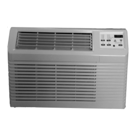
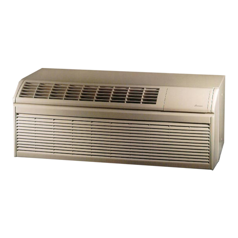
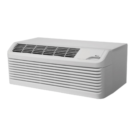
This
unit
is designed for through-the-wall installation in new or
existing buHdings. To complete theinstallation
of
this
PTAC,
an
insulated wall sleeve
and
an
outdoor grille (either the stamped
aluminum grille, the architectural grille or polymer grille) are
required.
The
chassis
and
the cabinet
front
are shipped
in
one carton.
Optional accessories to complete a particular installation are
the following:
OPTIONAL
ACCESSORIES
Power Switch Kit Wire
Harness
Kit
Wall Sleeve Kit Circuit Breaker Kit
Key
Lock Kit Architectural Grille Kit
Drain Kit Remote Escutcheon Kit
Filter Kit External Transformer Kit
Subbase
Kit Water or Steam Valve Kit
Hard Wire Kit Condensate Disposal
Pump
Kit
Main Duct Kit Remote Temperature
Sensor
Kit
Power Vent Kit Wireless
RF
Antenna
Leveling
Legs
Kit Wireless
RF
Thermostat
Hydronic Heat Kit Wireless Motion
Sensor
Stamped Grille Kit Wireless Door Switch
Deflector Grille Kit Wired Motion
Sensor
Polymer Grille Kit Wired Door Switch
Extension Duct Kit Extra
Deep
Sleeves
Wall Thermostat Kit
Fuse
Holder Kit
NOTE:
Consult sales literature for the appropriate voltage
and
amperage selections,
if
applicable. For additional details
and
illustrations
of
the accessories, refer
to
the Architect's
and
4 Engineer's Manual.

