Amana room air conditioner User manual

is a registered trademark of Maytag Corporation or its related companies
and is used under license to Goodman Company, L.P., Houston, TX. All rights reserved.
RoomAir Conditioner & Heat Pump
Use and Care Manual
Introduction
Roomairconditionerscool,dehumidify,andfilterairinside
yourhome. Heatpumpandelectricheatmodelsofferboth
heating and cooling. Opening sections of manual provide
general information for all room air conditioner models.
OperatingControlssectiondescribesoperationofcontrols
foreachmodel. Afterreading the opening sections,turnto
Operating Controls section and find the panel layout that
matches the model of your unit.
Readentiremanualthoroughlybeforebeginninginstallation
andoperationofyournewroomairconditioner. Besureyou
have all necessary tools and materials on hand for the job.
Study illustrations to familiarize yourself with important
details of the installation process. Review manual for
operatinginstructions.
NOTE
1. Mechanical experience is required to install air condi-
tioner.
2. Installation can take from 1 to 3 hours, depending on
installer’s knowledge and skill.
3. If you encounter problems during installation, call our
consumerinformationlinetoll-freeat1-877-376-0214. If
yourproblemcannotberesolvedbyphone,contactan
authorizedAmana®brandservicer. Contactandservice
will be at your expense.
IO-372B
©2010,2013 GoodmanCompany, L.P.
Effective:September2013
SafetyInformation
Besureelectricalserviceisadequateforchosenmodelofair
conditioner. Complete electrical rating for unit is found on
serialplatelocatedbehindfrontgrille.Electricaloutletmust
becloseenoughtounitforpowercordtoreachwithoutstrain.
Air conditioner should be the only appliance on individual
circuit.
For personal safety and to avoid possible damage to appli-
anceorhome,observeallsafetyinstructionshighlightedby
symbolshownbelow.
RECOGNIZE THIS SYMBOL AS A
SAFETY PRECAUTION.
Afterinstallingunit, reread instructionstoensure each step
iscompleteandthatallpartsarefastenedinplace.Forbest
results and to minimize installation time, perform all proce-
duresin the ordershown.
WARNING
Contents
Introduction.................................................................. 1
Safety Information....................................................... 1
Unpacking .................................................................... 2
Electrical Requirements.............................................. 2
Installation ................................................................... 3
Room Heat Pumps....................................................... 3
Normal Care & Maintenance ...................................... 3
General Instructions .................................................... 5
InstallationInstructions ............................................... 6
Through-The-Wall Installation Instructions ............. 12
Operating Controls .................................................... 15
Before Calling Service.............................................. 17
When Service Is Required ........................................ 18
AnyQuestions? .......................................................... 18
Warranty..................................................................... 20

2
WARNING
WARNING
HIGH TEMPERATURE STRESS HAZARD
This room air conditioner is not meant to provide
unattended cooling or life support for persons or
animals that are unable to react to failure of the
product.
The failure of an unattended air conditioner may
result in extreme heat in the conditioned space
causing overheating or death or persons or
animals.
Precautions must be taken to ward off or guard
against such an occurrence.
WARNING
Unpacking
Unpackandvisuallyinspecttheunit. Reportanydamageto
the delivering carrier immediately. Remove and discard all
packingmaterial.
Do NOT operate unit with shipping foam
blocks in place. Always remove prior to
running unit.
WARNING
Onsomemodelstheairconditionerfrontand/ormountingkit
hardwaremaybepackedseparately.
Recordthemodel,serialandmanufacturingnumbersofyour
unitinthespaceprovidedbelow. Thisinformationisfoundon
a nameplate visible after the front of the air conditioner has
beenremoved. Theratedvoltage,amperageandcapacityfor
your specific model can also be found on this nameplate.
Readthewarrantypackagedwiththeunit. Keepthewarranty
andacopyofyoursalesreceiptforfuturereference. Youmay
alsowanttorecordinthespaceprovidedthedatepurchased
andthe sellingdealer.
OWNER'S PRODUCT IDENTIFICATION
MODEL NUMBER
SERIAL NUMBER
MANUFACTURING NUMBER
Owner's Name
Address
City State Zip
/ /
Date of Purchase
Authorized Dealer
Address
City State Zip
( )
Phone Number
To avoid death, personal injury or property
damage due to electrical shock:
• Observe all local codes and ordinances.
•Disconnect electrical power to unit before servicing.
• Ground appliance properly.
• Check with a qualified electrician if you are not
sure this appliance is properly grounded.
• DO NOT ground to gas line.
• DO NOT ground to cold water pipe if pipe is
interrupted by plastic, non-metallic gaskets, or
other insulating (non-conducting) materials.
• DO NOT modify plug on power cord. If plug
does not fit electrical outlet, have proper outlet
installed by qualified electrician.
• DO NOT have a fuse in the neutral or ground
circuit. A fuse in the neutral or ground circuit
could result in an electrical shock.
• DO NOT use an extension cord with this appliance.
• DO NOT use an adapter plug with this appliance.
• DO NOT pinch power cord.
•DO NOT REMOVE warning tag from power cord.
WARNING
ElectricalRequirements
GroundingInstructions
Thisapplianceisequippedwithathree-pronggroundingplug
forprotectionagainstpossibleshockhazards. Ifatwo-prong

3
wallreceptacleis encountered, thecustomeris required to
contact a qualified electrician and have the two-prong wall
receptacle replaced with a properly grounded three-prong
wall receptacle in accordance with the National Electrical
Code.
Roomairconditionersaredesignedtooperateaccordingto
requirements on the nameplate and as shown in Table 1.
Fuseorcircuitbreakerratingsmustbeaccordingtothefuse
instructionlabelandasshowninTable1. Donotplugmodels
marked“UseonSingleOutletCircuitOnly”intoacircuitwith
anotherapplianceorlightfixture.
ReceptacleWiring
Receptaclewiring must beof adequate sizefor unit. Refer
tounitidentificationplate for exact powerrequirements.
Minimum size of wiring, based on power requirements, is:
Units up to 20 amps: 12gauge
20–30ampunits: 10gauge
Usecopperwireonly.Consumer’sresponsibilityistoprovide
properand adequatereceptacle wiringthat conformsto all
applicablecodes.Allwiringshouldbeinstalledby qualified
electrician.
LCDIorAFCIPowerCords
Underwriters Laboratories (UL) and the National Electric
Code (NEC) now require power cords that sense current
leakageandcanopentheelectricalcircuittotheunit. Inthe
event, the unit does not operate, check the reset button
locatedonornearthe head ofthepowercordaspartofthe
normaltroubleshootingprocedure.
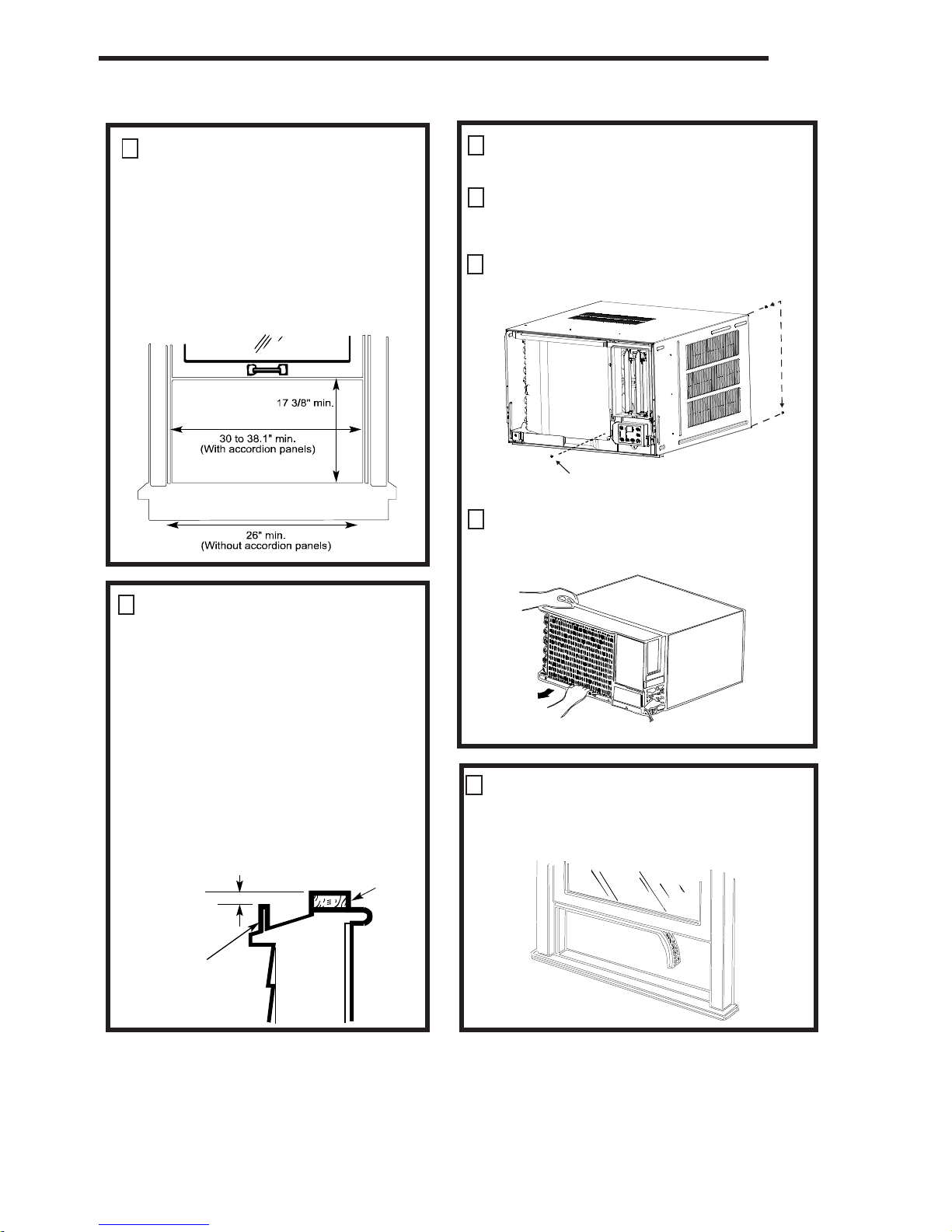
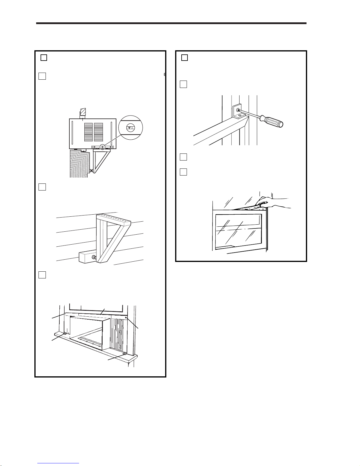
Installation
Completestep-by-stepinstallationinstructionsarefurnished
withyourunit. Theseinstructionswillbefoundonaseparate
page included with this manual or in the mounting kit
assembly. Followtheseinstructionscarefully. Keepthese
instructionswiththismanualforfuturereference. Yourunit
willbe one ofthefollowing designs:
•Unitwithawindowmountingkit
These models are designed for mounting though an
opening in a wall. These units can be adapted to
windowinstallationbyusingtheoptionalwindowmount-
ing kit supplied with your unit.
•Unitwithoutawindowmountingkit
No window mounting kit is supplied with the unit.
These models are designed for mounting through an
opening in a wall. These units can be adapted to
windowinstallationbypurchasinganoptionalwindow
mountingkit. Consultyourdealertochoosethekitthat
isappropriateforyourmodeland installation.
RoomHeatPumps
Heatpumpsworkbymovingheatinsteadofcreatingit. Inthe
summer, the cool indoor coil absorbs heat from your room
andmovesitoutdoors,providingcooling. Inthewinter,heat
pumpsreversethisoperation. Byloweringthetemperature
of the outdoor coil below the outdoor temperature, the heat
pump absorbs the heat from outdoors and moves it inside
yourhouse. Thisheattransferring processisveryefficient.
Forexample,at45°Foutdoortemperature,aheatpumpcan
provide 2 ½ watts of heat for every watt of electricity it
consumes.
As outdoor temperatures drop, the heating capacity and
efficiencyoftheheatpumpdeclines. Attemperaturesbelow
45°F, it is likely that ice will form on the outdoor coil. Heat
pump units are designed to operate as a heat pump above
approximately 40°F. Below 40°F, these units switch auto-
matically from reverse cycle heat pump to auxiliary electric
heating. No defrost is required. There is no minimum
operatingtemperature.
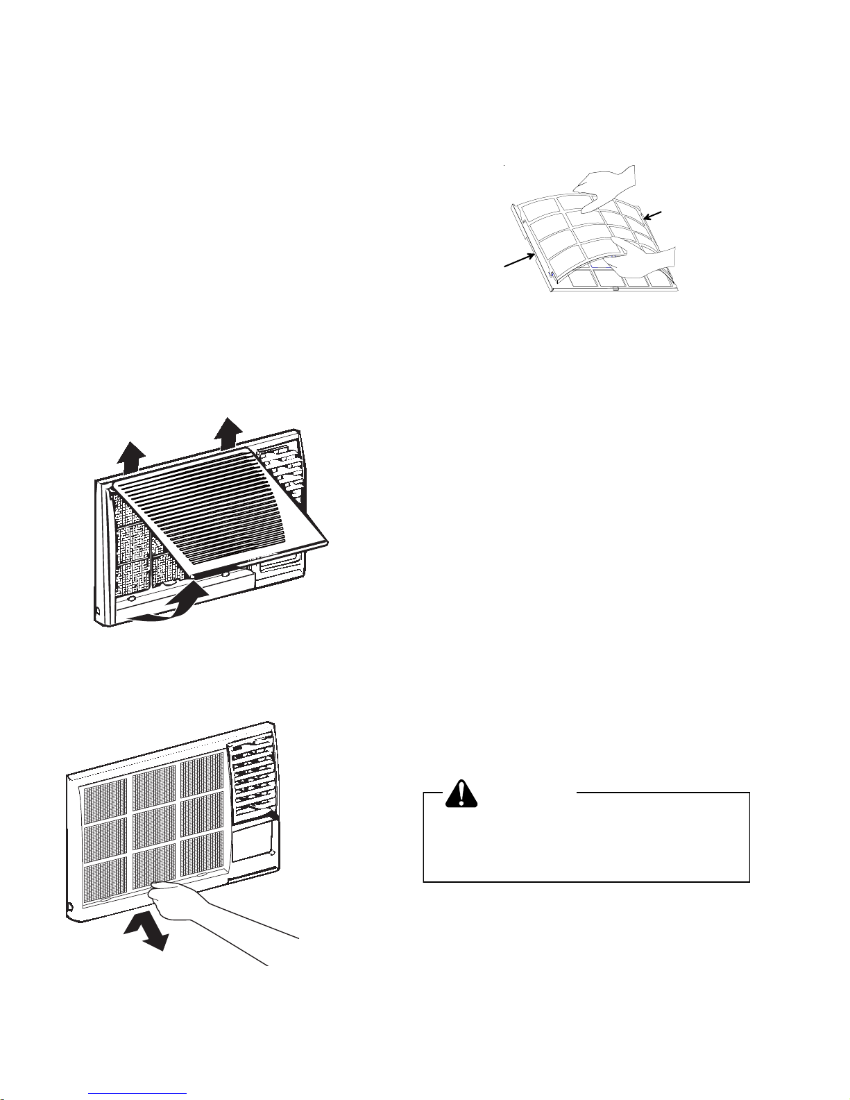
NormalCareandMaintenance
WARNING
Installing an air conditioner through a wall requires
extensive carpentry and/or masonry experience.
Thru-wall installations performed by inexperienced
or unqualified individuals can result in costly
damage to home or result in equipment malfunction
that could cause property damage, personal injury
or death.
CAUTION
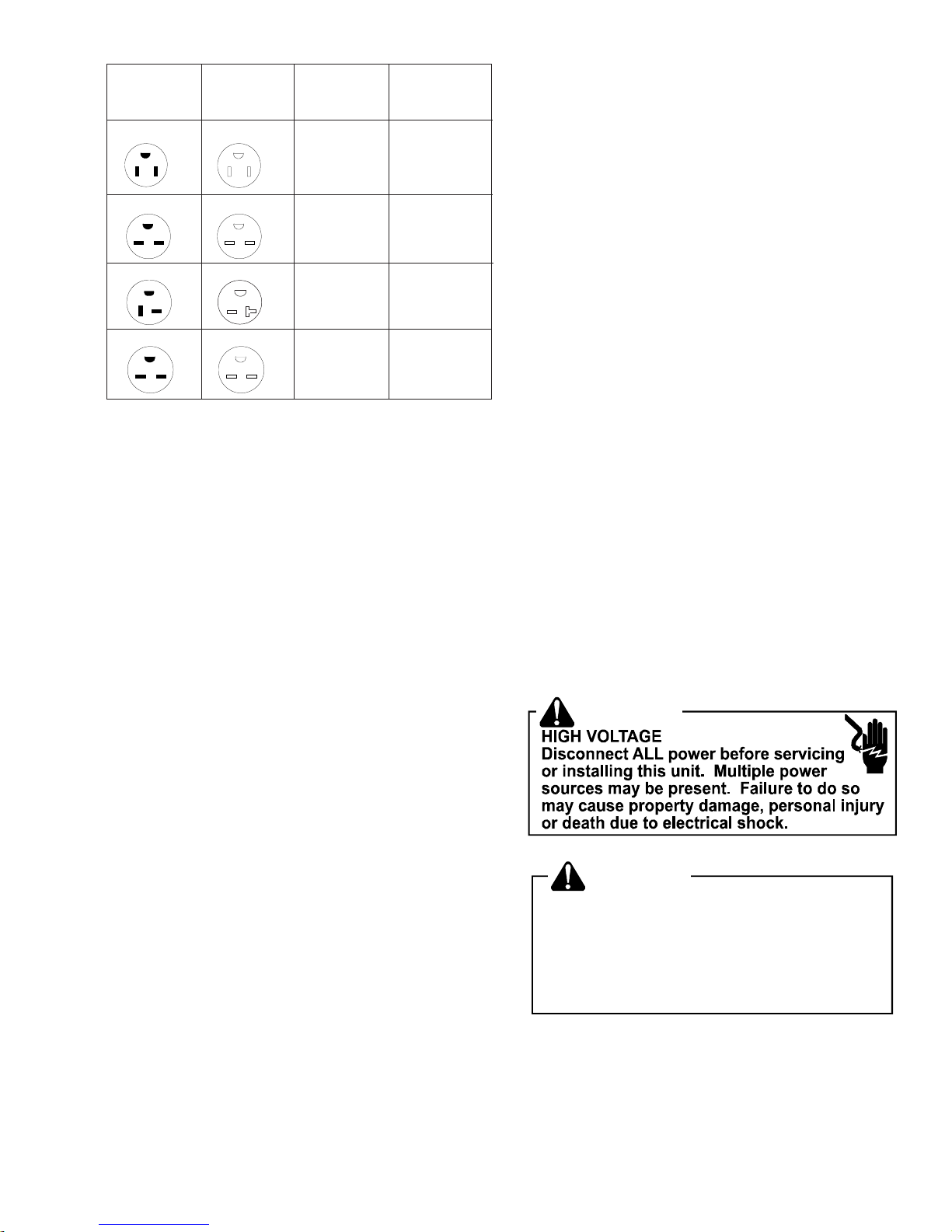
NEMA No. 5-15P NEMA No. 5-15R 125V-15AMP 115V
NEMA No. 6-15P NEMA No. 6-15R 250V-15AMP 230/208V rated
at 12 amperes or
less
NEMA No. 6-20P NEMA No. 6-20R 250V-20AMP 230/208Vrated
over 12 amperes,
but not more than
16 amperes
NEMA No. 6-30P NEMA No. 6-30R 250V-30AMP 208V rated over
16 amperes, but
not more than
24 amperes
Unit Plug Receptacle Circuit Rating, Voltage
Type Required Breaker, Time Rating On
Delay Fuse Nameplate

4
AnnualInspection
Itis suggested that yourunit be inspectedby your dealer or
servicer once a year. It is advisable to have the outer case
removedandtheunitthoroughlycleaned.
Note: Thelifeofyourunitmaybegreatly reducedifyoulive
inasaltairorothercorrosivetypeenvironment. Underthese
conditions, the unit should be removed from its case and
completely cleaned at least once a year. At that time any
scratches or blisters on the painted surfaces should be
sanded and repainted. Placing an algaecide tablet in the
outdoor side of the unit’s basepan is suggested in humid
areaswherealgaeformationiscommon. Werecommendthe
followingalgaecidecleaners:PanGuard®byControlReleased
Technologies, Inc. and CDC Anti-Clog®by Virginia KMP.
Front Grille and Filter Removal
Thefrontcontainsanairfilterthatcanberemoved.Toclean
thefilter,usethefollowingmethodforfilterremoval.
Graspexhaust grille andhinge up.
Grasp filter handle and slide filter out of unit.
OptionalCharcoalAirFilterInstallation
Removecharcoalair filterfromplasticbag.Insertthreetabs
onright side of filter into three slots on filter frame. Carefully
bowmiddleoffilteruntiltwotabsonfiltercanbeinsertedinto
two slots on filter frame. Relax bow.
Reinstallairfilterbyreversingremovalprocedure.
Front Grille and Cabinet Cleaning
Grilleandcabinetmaybecleanedwithwarmwaterandmild
soapordetergent.Cleaningandpolishingcompoundsarenot
recommended, as they may damage plastic surfaces.
Air Filter Cleaning
A dirty air filter reduces operating efficiency of unit. Filter
shouldbeinspectedatleastonceeveryweekduringopera-
tion.Cleanfilterwithvacuumcleanerorwashinwarmwater
andmilddetergent.Filtershouldbethoroughlydriedbefore
replacing in unit. Do not operate unit without filter in place.
Fan Motor Care
Thefanmotorispermanentlylubricatedforlonglife.Thereis
no need to oil the motor.
Slide-outChassisRemovalfromOuterCase
1. Hingefront grilleup.
2. Removeairfilterbygraspinghandleandliftingup.
3. Remove3screws(1eachsideand1behindfilter)holding
plasticfronttounitand remove front.
4. If the unit has a screw holding the basepan clip to the
chassis, remove the screw.
CAUTION
To reduce the risk of personal injury, be sure to
have sufficient help when moving your unit. A
room air conditioner can weigh between 70 and
240 pounds.
5. Usingbasepanhandle,pull chassis straightout,slowly
andevenly,untilapproximately9-12inchesextendsfrom
outer case. Use both hands to grasp basepan and pull
remainingchassis from outer case.
NOTE:Basepanclipisshippedinplasticbagwithmounting
screwandcondensatedraincup.Installclipafterreinserting
chassis into outer case to prevent accidental chassis re-
moval.

5
Plastic Front
Chassis
GeneralOperating Instructions
While operation of all units is similar, controls vary slightly
from model to model. Operating Controls section shows
controlpanelofunitpurchasedandgivesdetailedinformation
aboutoperationofcontrols.
InitialStart-UpandCooling
Selectthehighestfanspeedandsettemperaturecontrolto
its coldest position. When the desired temperature is
reached, slowly move the temperature control toward a
warmersettinguntilthe compressor shutsoff. Thethermo-
statwillthencyclethecompressoronandofftomaintainthis
selected temperature. Adjust the fan speed for desired air
circulation.
Outdoor
Louvers
Indoor
Grille
Baffles
ChangingAirflowDirectionBaffles
Airflow on unit may be diverted left or right from center by
baffles.Upwardanddownwardairdischargeisprovidedby
tiltinglouvers.Adjustbaffles and tiltlouversfordesired
airflow pattern. Unit also has automatic left to right air
movementwith"Circulaire"feature. (Seepage15under
OperatingControls.)
Airflow Around Unit
Checktheindoorgrilleandoutdoorlouversforobstructionsto
airflow. Donotblocktheairflowtoandfromtheunit. Ifairis
obstructed and/or deflected back into the unit, the air
conditioner’scompressormaycycleonandoffrapidly. This
coulddamageyourunit.
DrainCupInstallationandUse
Yourairconditionerusesasystemwherethewaterremoved
fromtheindoorair(condensate)ischanneledtotheoutdoor
side of the unit. The outdoor fan blade has a “slinger” ring
attachedtoitthatdipsintothewaterandslingsthewateronto
theoutdoorcoilsurface. Thisisthesoundofwateryouhear
duringnormaloperation. Thewaterquicklyevaporatesonthis
warmsurfaceandimprovestheefficiencyofyourairconditioner.
Innormalconditionstheunitcanevaporatethewaterasfast
as it is removed from the indoor air.
However, invery humid conditionsexcess amounts of water
may drip off the unit chassis. If this proves to be a problem,
installthecondensatedraincupincludedwith the unit to route
excesswaterwhereitwouldnotbeaproblem(see illustration
below).
Toinstall,removetheunitchassisfromtheoutercase. Insert
thecondensatedraincupthroughtherecessed½”holeonthe
backcenterflangeoftheoutercase. Onceinserted,placea
½”diameterhoseortubeonthedraincupbottomspout. The
hoseallowsyoutoroutewhereyouwanttheexcesswaterto
go. Reinsert the unit chassis into the outer case. The unit
basepan overflow hole will be positioned directly above the
drain cup and will catch any water that might run out.
1/2" Diameter
Hose
Condensate
Drain Cup
Outer Case
SwitchoverThermostatControl
Emergency heat switch overrides heat pump (compressor)
and starts auxiliary electrical heater. When switch is ON,
heat pump is locked out.
• Use emergency switch only when heat pump fails to
provideadequateheat. Causeofheatpumpmalfunc-
tionshouldbedeterminedbyauthorizedservicer.Cost
of operating unit will increase when emergency heat
switch is engaged.

6
Installation
Instructions Air Conditioner
BEFORE YOU BEGIN
Read these instructions completely and care-
fully.
• IMPORTANT-Savetheseinstructionsforlocal
inspector'suse.
• IMPORTANT-Observeallgoverningcodesand
ordinances.
• NotetoInstaller-Besuretoleavetheseinstructions
withtheConsumer.
• NottoConsumer-Keeptheseinstructionsforfuture
reference.
• Skilllevel-Installationofthisappliancerequiresbasic
mechanicalskills.
• Completiontime-Approximately1hour
• Werecommendthattwopeopleinstallthisproduct.
• Properinstallationistheresponsibilityoftheinstaller.
• Productfailureduetoimproperinstallationisnot
coveredundertheWarranty.
Question?Consumerinformationlinetoll-free1-877-376-0214
ELECTRICAL REQUIREMENTS
The3-pronggroundingplugminimizesthe
possibility of electric shock hazard. If the wall
outletyouplantouseisonlya 2-prong outlet, it is
yourresponsibilitytohaveit replaced with a
properlygrounded3-prongwalloutlet.
Somemodelsrequire230/208-volta.c.
protected with a time delay fuse or circuit
breaker.Thesemodelsshouldbeinstalledon
their own single branch circuit for best
performanceandtopreventoverloading
houseor apartment wiring circuits, which
couldcause a possiblefire hazardfrom
overheatingwires.
CAUTION
Do not, under any circumstances, cut or
remove the third (ground) prong from the
power cord.
Do not change the plug on the power cord of
this air conditioner.
Aluminum house wiring may present special
problems - consult a qualified electrician.
Powercordincludesacurrentinterrupter device.
Atest and resetbutton isprovidedon theplug
case.Thedeviceshouldbetestedonaperiodic
basisbyfirstpressingtheTESTbuttonandthen
theRESETbutton.IftheTESTbuttondoesnottrip
oriftheRESETbuttonwillnotstayengaged,
discontinueuseoftheairconditionerandcontacta
qualifiedservicetechnician.
Adjustablewrench
A
djustable wrench
WARNING DisconnectALLpowertounitbeforeinstallingorservicing,making
sureunitispluggedinonlywheninstructionsstateitissafetodoso.
Failuretofollowinstructionsmaycausepropertydamage,personal
injuryordeath.
Phillips head screwdriver
Level
Phillips head screwdriver
Pencil
Flat-blade screwdriver
Ruler or tape measure
Scissors or knife
TOOLS YOU WILL NEED

7
Type A (6)
V-support (2)
Window locking
bracket (2)
Top
mounting
rail
Right
accordion
panel
Foam top
window gasket
Window
sash seal
Left
accordion
panel
Type B (4) Type C (7) Type E (
Bolt (2) & nuts (2)
PARTS INCLUDED
(Appearance may vary)
Installation Instructions
Type D (6) Type E (4) Type F (2)
Installation Instructions

8
1/2" higher
than frame
Storm
window
frame
Wood
Stool
•Theseinstructionsareforastandarddouble-
hung window. You will need to modify them for
other types of windows.
•Theairconditionercanbeinstalledwithoutthe
accordion panels if needed to fit in a narrow
window.Seethe window openingdimensions.
•Allsupportingpartsmustbesecuredtofirm
wood,masonryormetal.
•Theelectricaloutletmustbewithinreach ofthe
power cord.
1 WINDOW REQUIREMENTS
•A storm window frame will not allow the air
conditionertotilt toward the outside, and will
keepitfromdrainingproperly.
To adjust for this, attach a piece of wood to
thestool.
WOODPIECES
WIDTH:2"
LENGTH:Longenoughtofitinsidethewindow
frame.
THICKNESS:Todeterminethethickness,placea
pieceofwood on thestoolto make it1/2"higher
than the top of the storm window frame.
Attach securely with nails or screws
providedbytheinstaller.
2STORM WINDOW REQUIREMENTS
Removethelockingscrewandlocking
bracket from the lower frame. Save to
reinstalllater.
Removetheground screw andsaveto
reinstalllater.
4PREPARE THE WINDOW
3 REMOVE THE AIR CONDITIONER
FROM THE CASE
A
B
Cut the window sash seal to the proper
length. Peel off the backing and attach the
seal to the underside of the window sash.
Installation Instructions
CSlidetheairconditionerfromthecaseby
grippingthebasepanhandleandpulling
forward while bracing the case.
Remove the ground screw and save to reinstall later.
Remove shipping screws
(if present) and discard
Installation Instructions

9
PREPARE THE CASE
Install the top mounting rail with 4 type B
screws from the inside of the case.
Insert the frames for the accordion panels
into the top mounting rail and the bottom
frame guides. Attach the accordion panels
to the side of the case using 3 type A screws
on each side.
N ote: When attaching the accordion panels,
make sure to only screw the inner panels
to the case sides.
B
A
5
Installation Instructions
Top mounting rail
Bottom frame guides
INSTALL THE CASE
IN THE WINDOW
Carefully slide the case into the window and
center the case. Lower the window behind
the top mounting rail. Pull the bottom of the
case forw ard s o that the bottom mounting
rail is tight agains t the back of the window
stool. Mount the case to the window s ill using
4 type E screws. Drill pilot holes, if neces s ary.
Make sure the bolts and nuts are all of the
way in both the left and right V-supports.
Position the V-supports on the case bottom
so that they will be near the outside wall.
Attach a V-support to each side of the
bottom of the cas e using type C screws,
3 on each side.
C
B
A
6
Bolt and nut
V-support
4 type E screw s
S tool
Make sure the bolts and nuts are all of the
way in both the left and right V-supports.
Stool
Installation Instructions
Position the V-supports on the case bottom
so that they will be near the outside wall.
Attach a V-support to each side of the
bottom of the case using type C screws,
3 on each side.
Carefully slide the case into the window and
center the case. Lower the window behind
the top mounting rail. Pull the bottom of the
case forward so that the bottom mounting
rail is tight against the back of the window
stool. Mount the case to the window sill using
4 type E screws. Drill pilot holes, if necessary.

10
Installation Instructions
INSTALL THE CASE
IN THE WINDOW (cont.)
Adjust the leveling bolts and nuts against the
outside wall so that the case has a slight tilt
to the outside. Tighten nuts with an adjustable
wrench. Use a level; about a 1/2 bubble will
be the correct case slant to the outside.
Use a wood block (obtained locally) between
the leveling bolts and the wall if the wall is
weak or if the weight of the air conditioner
falls between the studs in the wall.
E xtend the left and right accordion panels
to the vertical window sashes. Drill pilot
holes and attach the top and bottom corners
with 4 type D screws .
F
E
D
6
Type D
screw Type D
screw
Type D
screw
Top mounting rail
Type D
screw
INSTALL SUPPORT BRACKETS
AND THE FOAM TOP WINDOW
GA S K E T
Attach the support brackets with two
type D screw s, one on each s ide.
Cut the foam top window gas ket to the
window width.
Stuff the foam between the glass and the
window to prevent air and insects from
getting into the room.
C
B
A
7
Adjust the leveling bolts and nuts against the
outside wall so that the case has a slight tilt
to the outside. Tighten nuts with an adjustable
wrench. Use a level; about a 1/2 bubble will
be the correct case slant to the outside.
Installation Instructions

11
INS TALL THE AIR CONDITIONER
IN THE CASE
Slide the air
conditioner into
the case. Do not
push on the
controls or the
finned coils .
Make sure the
air conditioner
is firmly seated.
Reinstall the locking bracket and s crew
removed earlier.
Reconnect the ground wire to the air
conditioner using the s crew rem oved earlier.
IMPOR TANT: The ground wire must be
reinstalled to ensure a proper ground.
Remove the front grille from its box and
remove the shipping tape.
Grasp the inlet grille at the bottom corners
and pull it forward. Unhook it from its top
hinges and set it aside.
Using the tab, pull up slightly on the filter
to release it and pull it down and out.
F
E
D
C
B
A
8
Installatio n Instructio ns
INSTALL THE AIR CONDITIONER
IN THE CASE
(cont.)
Pull the coiled power cord from its shipped
position in the air discharge area. Attach
the front grille frame to the case by inserting
the tabs on the grille frame into the slots
on the front top of the cas e. Push the grille
frame in. And install the 2 side screws at bottom
left and right side of front panel.
Secure the front grille frame to the cas e
with one type C s crew.
Reinstall the filter.
Reinstall the inlet grille. Connect power.
J
I
H
G
8
Guide the lever carefully
through the grille fram e
as you push it in.
Remove the front grille from its box and
remove the shipping tape.
Slide the air
conditioner into
the case. Do not
push on the
controls or the
finned coils.
Make sure the
air conditioner
is firmly seated.
Installation Instructions
Pull the coiled power cord from its shipped
position in the air discharge area. Attach the
frontgrilleframe tothecase byinsertingthetabs
on the grille frame into the slots on the front top
of the case. Push the grille frame in. Install the
2TypeFscrewsatthebottomleftandrightsides
of the front panel.

12
Dimension of Bottom Rail
/
2
"
3”
Front of
outer case Bottom rail
26”
9”
16 7/8”
A
E18: 25 3/5”
18: 28 1/3”AH
Outer Case Dimensions
(chassisremoved)
GeneralInstructions
AllAmana®brandCompact RoomAir Conditioners feature
a slide-out chassis. Chassis and front cover must be re-
movedfromouter case forinstallation.
Introduction
Thisinstruction sheet providesguidelinesfor installing a
compactair conditioner throughan outside wall.
WARNING
Installing an air conditioner through a wall requires
extensive carpentry and/or masonry experience.
Thru-wall installations performed by inexperienced
or unqualified individuals can result in costly
damage to home or result in equipment malfunction
that could cause property damage, personal injury
or death.
CAUTION
Air Conditioner Dimensions
Thefollowingfigures show theoutside dimensions of air
conditioner with chassis installed, and dimensions of outer
casewith chassis removed.
Thru-wall Installation Instructions
for Amana®Brand Room Air Conditioner
is a registered trademark of Maytag Corporation or its related
companies and is used under license to
Goodman Company, L.P., Houston, TX. All rights reserved.
Air Conditioner Dimensions
(with chassis installed)

13
In order to reinstall the chassis and re-
attach the air conditioner front cover, the
installed outercase must be square and
level from side to side. Use wood shims
between sides of case and finished open-
ing - especially where case is secured to
opening - to prevent warping or distorting.
Check installed case for distortion using
carpenter's square.
CAUTION
Afinished opening 26 1/8-inches widex 17-inches high is
recommended.Thelower left insidecornerof opening must
bewithin 5 feet of an appropriate electrical outlet (see Use
andCaremanualfor electrical requirements.)
When wall thickness exceeds 9-inches, opening must be
modified to allow air to enter side louvers on case (see spe-
cial instructions on back ). Do not install air conditioner in
walls thicker than 11 2/5-inches.
Brick Veneer or Frame Wall Construction
See CAUTION under General Instructions. Cut or build
roughopeninglargeenough to allow aframed,finished
opening17-inches high and 261/8-incheswide.When case
is properly positioned in opening, secure it to framing mate-
rial with nails or screws driven through holes in sides of
outercase (shim caseand predrill holes before securing).
Framing
lumber
26 1/8”
17”
Framed/Finished Opening
(brickveneerorframe wall construction)
Placement of Outer Case in Opening
Place outer case in opening, flush against one side of
opening.Use carpenter’s level andensure case islevel
from side to side and has a 3/8-inch slope from front to back
(back of case must be 3/8-inch lower than front to ensure
propercondensatedrainage). If needed, useshimsto level
case (from side to side) and to obtain proper back slope.
Front of case must project ¾-inch (minimum) beyond in-
sidewall in order to attachair conditioner front frame. If
framingindoorside of opening withwoodmolding (or other
decorativematerial),extend outer case¾-inchbeyond
molding.
When case is properly positioned in opening, use wood
shims to fill any gaps between case and finished opening,
especially in area where case will be secured to opening.
Take care not to warp or distort case when installing
shims.For condensate drainage, installdrainage cup in
drainhole on baseplateof case.
Dimensions of Finished Opening
Masonry Construction
See CAUTION under General Instructions. In masonry
walls, cut or build a finished opening 17-inches high by
261/8-inches wide. When case is properly positioned in
opening, secure it in place with mortar or concrete nails
driven through holes in sides of outer case (shim case and
predrillholesbefore securing withnails).

14
Caulk all
sides
Lintel and
flashing
(if required)
Outercase must project
a minimum ¾"
beyond inside wall
or molding to attach front frame
9
3
/
8
"
with
3
/
8
"
drainage
Front of outer case
to side air louvers
Optional
molding
(not provided)
Installed Case
(brickveneerorframe wall constructionshown)
Installation in Wall
Thicker Than 9-inches
Thesidelouvers in outercaseprovide ventilation toaircon-
ditionercompressor and fan motor andmust notbe
blocked. When installing unit in a wall over 9-inches thick,
provisionsmust be madein wall openingto ensure freeair
flow to the side louvers. This can be accomplished by
chamferingthe vertical portions ofthe outside openingas
shown.
Ventilation louvers on top of case must not be obstructed.
Do not attempt to install unit in walls thicker than
112/5-inches.
5
Chamfering Walls Thicker Than 9-inches

15
Operating Controls
Operatingyourairconditionerproperlyhelpsyoutoobtainthe
best possible results.
Thissectionexplainsproperairconditioneroperation.
IMPORTANT:
• Ifyouturnofftheairconditioner,waitatleast3minutes
before turning it back on. This prevents the air condi-
tionerfromblowingafuseortrippingacircuitbreaker.
• Donottrytooperateyourairconditionerinthecooling
modewhenoutsidetemperatureisbelow61°F(16°C).
Donottrytooperateyourairconditionerintheheating
modewhenoutsidetemperatureisover86°F(30°C).
NOTES:
1. NOTE: Factory default setting is for °F. To convert to
°C, press the INCREASE
/ DECREASE
buttons
simultaneously for approximately 5 seconds. To return
to°F,repeat the procedure.
2. In the event of a power failure, your air conditioner will
operate at the previous settings when the power is
restored.
Lights next to the touch pads on the air conditioner control
panel indicate the selected settings.
Controls
nPowerPad(Button)
Turnsair conditioner onand off. Whenturned on, the
displaywill show theroom temperature.
oDisplay
Shows the Set temperature when in HEAT, COOL or
ENERGY SAVER mode; shows the time remaining on
the Delay Timer; shows the room temperature when in
Fan Only mode. TheSET lightwill turn on whilesetting.
pTempIncrease/DecreasePads
Use to set temperature when in HEAT (on some mod-
els), COOL or ENERGY SAVER mode. The SET light
will turn on while setting.
qDelayTimerIncrease(+) /Decrease(-)Pads
Eachtouch of the INCREASE
/ DECREASE
pads
on the unit or the INCREASE (+) / DECREASE (-) pads
on the remote control will set the delay time when using
the DELAY 1-24 HR timer .
The SET light will turn on while setting.
rFanSpeedPads
Useto set thefan speed toLOW, MED, HIGH orAUTO,
on the unit.
NOTE: On the remote control, use the fan speed IN-
CREASE(+)/DECREASE(-) pads to set thefanspeeds
to LOW, MED or HIGH. Use the AUTO pad to turnAuto
fanon.
sMode Pad
UsetosettheairconditionertoCOOL, ENERGYSAVER,
FAN ONLY orHEAT (on some models)mode.
tTimerPads
TIMER ON - Whenthe air conditioneris off, itcanbe set
to automatically come on in 0.5 (1/2 hr.) to 24 hours at
itsprevious mode andfan settings.
TIMER OFF - When the air conditioner is on, it can be
set to automatically turn off in 0.5 (1/2 hr.) to 24 hours.
control panel indicate the selected settings.
Set
TIMER
SWING
-
FAN
SPEED
MED
HIGH
LOW
AUTO
POWER
COOL
FAN ONLY
HEAT
MODE 1-24 HR
ENERGY SAVER
TEMP/TIMER
+
Light indicates the
delay timer is set.
Light indicates the unit
is in the temperature or
delay time Set mode.
The display always shows the room
temperature except when setting the
Set temperature or the Delay timer.
Air Conditioner Controls
Light indicates
SWINGis on.
Light indicates
SWING is on.
The display always shows the room
temperature except when setting the
Set temperature or the Delay timer.
Light indicates the unit is in the temperature or
delay time Set mode.
pq
7
Delay 1-24 hr
4
Delay timer
Decrease
5
Mode select
6
5
Fan speed
Decrease
5
5
Temperature
set Increase
and Decrease
3
The display shows the Set temperature
when in HEAT, COOL or ENERGY SAVER
mode. It also shows the time remaining on
the Delay timer and the room temperature
when in Fan Only mode.

16
Howtoset:
Press the TIMER 1-24 hr pad on the unit or the pad
onthe remotecontrol. Eachtouch ofthe INCREASE
/ DECREASE padsontheunitortheINCREASE (+) /
DECREASE (-) pads on the remote control will set the
timerin 0.5 (1/2 hr.) or1-hour intervals. (The delaytimer
can be set in 0.5 (1/2 hr.) increments if programmed for
under10 hours, but if thedelay timer is set forabove10
hours, the timer will be set in 1-hour increments.) The
SET light will turn on while setting.
ToreviewtheremainingtimeontheTIMER 1-24hrtimer,
presstheTIMER 1-24 hr pad on theunit or the pad
on the remote control. Use the INCREASE / DE-
CREASE pads on the unit or the INCREASE (+) /
DECREASE (-) pads onthe remote controlto set anew
time if desired.
To cancel the timer, pressand hold the TIMER 1-24 hr
pad until the light on the TIMER 1-24 hr pad goes off.
uSwingPad
Turnontoprovidecontinuousside-to-sideair circulation.
For fixed side-to-side air direction, turn on until the de-
sired air direction is obtained, then turn it off.
RemoteControl:
• Toensureproperoperation,aimtheremotecontrolat
thesignalreceiverontheairconditioner.
• Theremotecontrolsignalhasarangeofupto20feet.
• Makesurenothingis betweentheairconditionerand
the remote control that could block the signal.
• Make sure your batteries are fresh and installed cor-
rectly as indicated on the remote control.
Cool Mode
Use the COOL mode at LOW, MED, HIGH, or AUTO
FAN SPEED for cooling. Use the TEMPERATURE IN-
CREASE / DECREASE pads to set the desired
temperaturebetween61° and 86°Fin 1° increments.
Thecompressorwillcycleon and off tokeeptheroomat
the set level of comfort. Set the thermostat at a lower
number and the indoor air will become cooler. Set the
thermostatata higher numberandthe indoor airwillbe-
comewarmer.
NOTE: If the air conditioner is off and then turned on
while set to a COOL setting, or if it is turned from a fan
setting to a COOL setting, it may take approximately 3
minutesforthecompressorto start and cooling tobegin.
CoolingDescriptions
ForNormalCooling - SelecttheCOOL modeandHIGH
orMED fan with a middle settemperature.
For Maximum Cooling - Select the COOL mode and
HIGH fanwith a lowerset temperature.
For Quieter & Nighttime Cooling - Select the COOL
mode and LOW fan with a middle set temperature.
Energy Saver Mode
Controlsthefan.
ON - The fan will cycle on and off with the compressor.
This results in wider variations of room temperature
and humidity and is normally used when the room is
unoccupied.
NOTE:Thefanmaycontinueto run for ashorttimeafter
the compressor cycles off.
OFF - The fan runs all the time, while the compressor
cycles on and off.
Fan Only Mode
Use the FAN ONLY mode at LOW, MED or HIGH fan
speedtoprovideaircirculation and filtering withoutcool-
ing. Sincethefanonly settings donotprovidecooling, a
SETtemperaturecannotbeentered.The room tempera-
ture will appear in the display.
NOTE:AutoFanSpeedcannotbeusedwhenintheFAN
ONLYmode.
Heat Mode (on some models)
UsetheHEAT modeatLOW,MED,HIGHorAUTO FAN
SPEEDforheating. UsetheTEMPERATUREINCREASE
/ DECREASE pads to set the desired tempera-
turebetween 61°F and86°F in 1°F increments.
Auto Fan Speed
Set to AUTO fan speed for the fan speed to automati-
cally set to the speed needed to provide optimum com-
fortsettings with the set temperature.If the room needs
morecooling, the fanspeed will automaticallyincrease.
If the room needs less cooling, the fan speed will auto-
maticallydecrease.
NOTE: AutoFanSpeedcannotbe used whenintheFAN
ONLYmode.
PowerOutageRecoveryFeature
Inthecaseofa power outage or interruption,theunitwill
automatically re-start in the settings last used, after the
powerisrestored. If theTIMER 1-24 hr feature wasset,
it will resume countdown. You may need to set a new
time if desired.

17
BEFORECALLINGSERVICE
PROBLEM POSSIBLE CAUSE SUGGESTED REMEDY
UNIT WILL NOT RUN No power to unit Push reset button on power cord.
Set Fan Control to position other than OFF.
Make sure plug is firmly seated in outlet.
Check for blown fuses, tripped circuit breakers.
LITTLE OR NO COOLING
LITTLE OR NO HEATING
(fan and compressor run)
Fresh air/exhaust damper open
Obstructed indoor or outdoor airflow
Dirty air filters
Unit undersized for application
Set vent to CLOSED.
Remove obstruction from indoor grille or outdoor louvers.
Dirty air filter. Clean or replace, as needed.
Check with dealer to determine proper capacity unit for application.
LITTLE OR NO COOLING
LITTLE OR NO HEATING
(only fan runs)
Temperature Control not set properly For cooling, turn Temperature Control to cooler setting.
For heating, turn Temperature Control to warmer setting.
NOISY UNIT Loose front on mounting assembly
Weak building construction
Water hitting fan blade
Unit oversized for application:
compressor cycles on and off frequently
Tighten any loose parts.
Provide additional support for unit.
Normal in high humidity. Stop noise by removing drain plug or
adding condensate drain cup.
Check with dealer to determine proper capacity unit for application.
MOUNTING SUPPORT NOT
INSTALLED Storm window frame installed in window Some models require removal of storm window frame before
installation.
FROST ON INDOOR COIL Dirty air filter
Normal for low outdoor temperatures
Clean air filter by vacuuming or washing with water and mild soap.
Turning Temperature Control to warmer setting reduces occurrence
and duration of frost.
FROST ON OUTDOOR COIL
(heat pump models only) Normal for outdoor temperatures at or
below 45°F Call for service only if unit does not heat room and you have
checked all problems and remedies listed under LITTLE OR NO
HEATING.
ODORS IN COOLING Mold, mildew, or algae formation on wet
surfaces To reduce algae growth, use algaecide tablet in base pan; remove
drain plug; add condensate drain cup and hose. Thoroughly clean
unit.
ODORS IN HEATING Normal for first time electric heater is
used each season Caused by dust accumulation during unused months.
Odor dissipates quickly with heater use.
Thefollowingisalistofproblemsthataresometimesencounteredwhenusingaroomairconditioner. Possiblecauseand
suggestedremediesaregivenforeachproblem.
If the problem cannot be fixed using the suggested remedies, see WHEN SERVICE IS REQUIRED section.
WARNING

18
When Service Is Required
Your room air conditioner dealer can give you the name of
your nearest Authorized Service Center. Help them give
you prompt service by providing:
• An accurate description of problem.
• Completemodel,serial,andmanufacturingnumbers
fromserialplate.
• Proofofpurchase(salesreceipt)uponrequest.
Repairbyunauthorizedservicerthatresultsinsubsequent
failure of unit voids warranty. Warranty details are con-
tained in warranty certificate enclosed with unit.
Keepaccuraterecordsofservicecalls,includingwhat was
done, servicer’s name, and date of service.
AnyQuestions?
Mostquestionscanbeansweredbyyourlocaldealer. Ifyou
have other matters that cannot be resolved locally, or you
need additional information regarding other heating and
cooling products offered by us - please call:
CONSUMERINFORMATIONLINE
AMANATOLLFREE
1-877-376-0214 (U.S. and Canada only)
fax us at: (713) 856-1821
(Not a technical assistance line for dealers.)
Outside the U.S. and Canada, call 1-713-861-2500.
(Not a technical assistance line for dealers.)
Your telephone company will bill you for the call.

19
LIMITED WARRANTY
CONSUMERS
WARRANTY LIMITATIONS:
WE ARE NOT RESPONSIBLE FOR:
• Damage or repairs required as a result of faulty installation or application
• Damage or repairs required as a result of floods, fires, wind, lightning, accidents, corrosive
atmosphere or other conditions beyond our reasonable control
• Damage or repairs required as a result of the use of components or accessories not
compatible with the unit
• Units installed outside of the United States and Canada
• Normal maintenance, as described in the installation and operating manual, such as
cleaning of the coils, filter cleaning and/or replacement, or damage caused by failure to
perform such maintenance
• Parts or accessories not supplied or designated for use by us
• Damage or repairs required as a result of any improper use, maintenance, operation or
servicing
• Damage or failure to start due to interrupted and/or inadequate electrical service
• Changes in the appearance of the unit that do not affect its performance
• Replacement of fuses and replacement or resetting of circuit breakers
THIS WARRANTY IS THE ONLY EXPRESS WARRANTY PROVIDED ON THE UNITS COVERED;
AND ANY IMPLIED WARRANTIES, INCLUDING ANY IMPLIED WARRANTY OF MERCHANT-
ABILITY OR FITNESS FOR A PARTICULAR PURPOSE ARE LIMITED TO THE DURATION OF
THIS WARRANTY. Some states and provinces do not allow limitations on how long an implied
warranty lasts, so the above limitation may not apply to you.
WHETHER ANY CLAIM IS BASED ON NEGLIGENCE OR OTHER TORT, BREACH OF WAR-
RANTY OR OTHER BREACH OF CONTRACT, OR ANY OTHER THEORY, IN NO EVENT SHALL
WE BE LIABLE FOR INCIDENTAL OR CONSEQUENTIAL DAMAGES, INCLUDING BUT NOT
LIMITED TO LOST PROFITS, LOSS OF USE OF A UNIT OR OTHERWISE. Some states and
provinces do not allow the exclusion or limitation of incidental or consequential damages, so
the above exclusion may not apply to you.
This warranty gives you specific legal rights, and you may also have other rights which vary
from state to state or province to province.
RAC WINDOW TYPE H & C (AE,RAC WINDOW TYPE H & C (AE,
RAC WINDOW TYPE H & C (AE,AH, PBC, PBE, PBH)AH, PBC, PBE, PBH)
AH, PBC, PBE, PBH)AH, PBC, PBE, PBH)
AH, PBC, PBE, PBH)
is a registered trademark of Maytag Corporation or its related companies and is used under license to Goodman Company, L.P., Houston, TX. All rights reserved.
For service, contact an Authorized Amana
®
Brand Servicer.
For answers to questions regarding the above or to locate an authorized servicer, contact
Goodman Consumer Affairs • 7401 Security Way • Houston, Texas 77040
1-877-254-4729 inside U.S.A. • 1-713-861-2500 outside U.S.A. ©
2010 Goodman Company, L.P.
Part No. PW-342C
12/2010
This warranty is extended only to purchasers for personal, family or household use. A
distinct warranty is extended to commercial customers.
Amana® brand RAC window-type heating or air conditioning units identified as AE, AH,
PBC, PBE and PBH units are warranted by Goodman Company, L.P. to consumers
against defects in materials and workmanship under normal use and maintenance, as
provided below.
FIRST-YEAR COVERAGE (ENTIRE UNIT): We will repair or replace, free of charge (to
include labor), any part of a unit that proves to be defective due to workmanship or
materials within the first year after the date of purchase.
SECOND THROUGH FIFTH YEARS SEALED SYSTEM COVERAGE: During the 2
nd
through 5
th
years after the date of purchase, we will repair (to include labor) any refrig-
erant leaks caused by defects in workmanship or material of a unit, and will repair or
replace (to include labor) any portion of the evaporator coil, condenser coil, compressor,
reversing valves or connecting tubing that proves to be defective, in workmanship or
materials.
If the date of purchase cannot be verified, the warranty period begins three months after
the month of manufacture (indicated by the first four digits of the unit’s serial number
(yymm)).
Any part replaced or leak repaired under this warranty is warranted only for the unex-
pired portion of the original warranty term.
The above remedies are our only responsibilities, and the consumer’s only remedies,
under this warranty. For warranty credit, any defective part must be returned to an
Amana® brand heating and air conditioning products distributor by an authorized
Amana® brand servicer; and all warranty service must be performed by an authorized
Amana® brand servicer. To locate an authorized Amana® brand servicer, contact
Goodman Company Consumer Affairs at the number or address found at the bottom of
this certificate.
Goodman will not pay for electricity or fuel costs, or increases in electricity or fuel costs,
for any reason, including additional or unusual use of supplemental electric heat. This
warranty does not cover lodging.
Model # & Serial # _________________________________ Date of Purchase _________________________________

20
11
is a registered trademark of Maytag Corporation or its related companies and is used under license to Goodman Company, L.P., Houston, TX. All rights reserved.
For service, contact an Authorized Amana
®
Brand Servicer.
For answers to questions regarding the above or to locate an authorized servicer, contact
Goodman Consumer Affairs • 7401 Security Way • Houston, Texas 77040
1-877-254-4729 inside U.S.A. • 1-713-861-2500 outside U.S.A. ©
2010 Goodman Company, L.P.
Part No. PW-343
5/2010
WW
WW
WARRANTY TO COMMERCIALARRANTY TO COMMERCIAL
ARRANTY TO COMMERCIALARRANTY TO COMMERCIAL
ARRANTY TO COMMERCIAL CUSTOMERSCUSTOMERS
CUSTOMERSCUSTOMERS
CUSTOMERS
This warranty is extended to commercial customers only. A distinct warranty is
extended to purchasers for personal, family or household use.
Amana® brand RAC window-type heating or air conditioning units identified as AE,
AH, PBC, PBE and PBH units are warranted by Goodman Company, L.P. to commercial
customers against defects in materials and workmanship under normal use and
maintenance, as provided below.
FIRST-YEAR COVERAGE (ENTIRE UNIT): We will repair or replace, free of charge
(to include labor)
, any part of a unit that proves to be defective due to workmanship
or materials within the first year after the date of purchase.
SECOND THROUGH FIFTH YEARS SEALED SYSTEM COVERAGE: During the 2
nd
through 5
th
years after the date of purchase, we will repair
(to include labor)
any
refrigerant leaks caused by defects in workmanship or material of a unit, and will
repair or replace
(to include labor)
any portion of the evaporator coil, condenser coil,
compressor, reversing valves or connecting tubing that proves to be defective, in
workmanship or materials.
If the date of purchase cannot be verified, the warranty period begins three months
after the month of manufacture (indicated by the first four digits of the unit’s serial
number (yymm)).
Any part replaced or leak repaired under this warranty is warranted only for the
unexpired portion of the original warranty term.
The above remedies are our only responsibilities, and the customer’s only remedies,
under this warranty. For warranty credit, any defective part must be returned to an
Amana® brand heating and air conditioning products distributor by an authorized
Amana® brand servicer; and all warranty service must be performed by an autho-
rized Amana® brand servicer. To locate an authorized Amana® brand servicer,
contact Goodman Company Consumer Affairs at the number or address found at the
bottom of this certificate.
Model # & Serial #
_________________________________
Date of Purchase
_________________________________
Goodman will not pay for electricity or fuel costs, or increases in electricity or fuel
costs, for any reason, including additional or unusual use of supplemental electric heat.
This warranty does not cover lodging.
WARRANTY LIMITATIONS:
WE ARE NOT RESPONSIBLE FOR:
• Damage or repairs required as a result of faulty installation or application
• Damage or repairs required as a result of floods, fires, wind, lightning, accidents,
corrosive atmosphere or other conditions beyond our reasonable control
• Damage or repairs required as a result of the use of components or accessories
not compatible with the unit
• Units installed outside of the United States and Canada
• Normal maintenance, as described in the installation and operating manual, such as
cleaning of the coils, filter cleaning and/or replacement, or damage caused by
failure to perform such maintenance
• Parts or accessories not supplied or designated for use by us
• Damage or repairs required as a result of any improper use, maintenance, opera-
tion or servicing
• Damage or failure to start due to interrupted and/or inadequate electrical service
• Changes in the appearance of the unit that do not affect its performance
• Replacement of fuses and replacement or resetting of circuit breakers
THIS WARRANTY IS PROVIDED IN LIEU OF ANY OTHER WARRANTIES, EXPRESS OR
IMPLIED, INCLUDING ANY IMPLIED WARRANTY OF MERCHANTABILITY OR FIT-
NESS FOR A PARTICULAR PURPOSE. WHETHER ANY CLAIM IS BASED ON NEGLI-
GENCE OR OTHER TORT, BREACH OF WARRANTY OR OTHER BREACH OF CON-
TRACT, OR ANY OTHER THEORY, IN NO EVENT SHALL WE BE LIABLE FOR INCIDEN-
TAL OR CONSEQUENTIAL DAMAGES, INCLUDING BUT NOT LIMITED TO LOST
PROFITS, LOSS OF USE OF A UNIT OR OTHERWISE.
RAC WINDOW TYPE H & C (AE,RAC WINDOW TYPE H & C (AE,
RAC WINDOW TYPE H & C (AE,AH, PBC, PBE, PBH)AH, PBC, PBE, PBH)
AH, PBC, PBE, PBH)AH, PBC, PBE, PBH)
AH, PBC, PBE, PBH)
Table of contents
Other Amana Air Conditioner manuals

Amana
Amana AMAP081BW User manual

Amana
Amana 10M52TA-P1214708R User manual

Amana
Amana PGA**C User manual

Amana
Amana PACKAGE TERMINAL Service manual

Amana
Amana APG16 M Series User manual

Amana
Amana AAC051SRA User manual

Amana
Amana AMAP084AW User manual

Amana
Amana VCA Operating instructions

Amana
Amana APG14 M Series Manual

Amana
Amana GSH13018 Operating instructions

Amana
Amana APN14J User manual

Amana
Amana RSC Ultron User manual

Amana
Amana ACE15KE User manual

Amana
Amana DigiSmart PTC models User manual

Amana
Amana ACD105E User manual

Amana
Amana SC-415 Service manual

Amana
Amana 10c5ez Assembly instructions

Amana
Amana ACE156E User manual

Amana
Amana AMAP222BW User manual

Amana
Amana RCA User manual