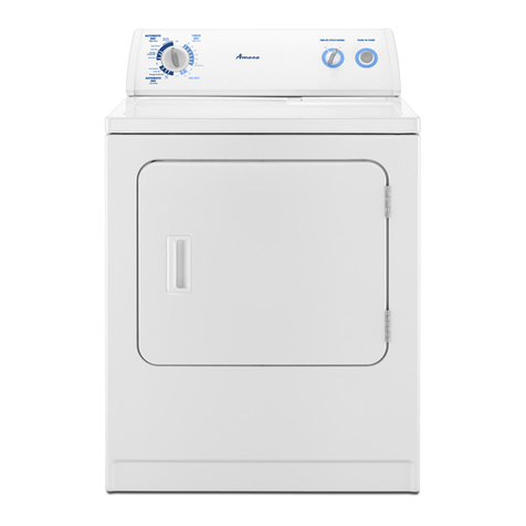
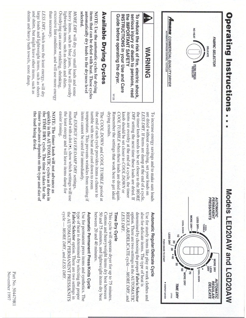
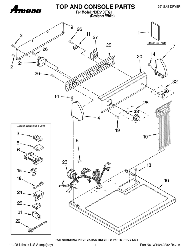
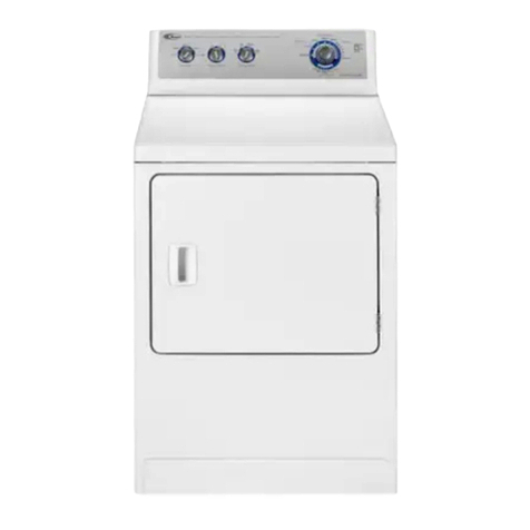
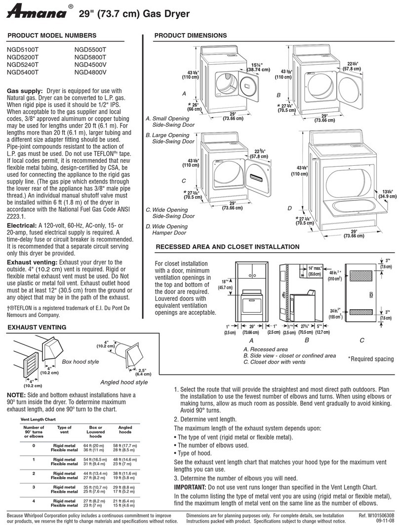
Amana ALE643RA series Manual

Amana Domestic Electric DryerTechnical Information
October 2001 RT3220006 Rev. 31
240 V, 60 Hz Models
ALE643RA* PALE643RA* ALE643RC*PALE643RC*
ALE643RB* PALE643RB* ALE643RC*PALE643RC*1
•Due to possibility of personal injury or property damage, always contact an authorized technician for servicing or
repair of this unit.
•This technical sheet replaces RT3220006 Rev. 2.
•Refer to Service Manual RS3200007 for detailed installation, operating, testing, troubleshooting, and disassembly
instructions.
•Refer to Parts Manual RP3200024 for part number information.
CAUTION!
All safety information must be followed as provided in this Technical Sheet and in Service Manual RS3200007.
!WARNING
To avoid risk of electrical shock, personal injury or death; disconnect power to washer before servicing, unless testing
requires power.
Models ALE643RA*
ALE643RB*
ALE643RC*
ALE643RC*1
Models ALE643RA*
ALE643RB*
ALE643RC*
ALE643RC*1
Power Source Temperature settings 4
Voltage AC 240 VAC Color coded control Electromechanical
Bi-directional
Amperage (Single Unit) 30 A Features
Frequency 60 Hz Easy AccessOpening X
Motor horsepower 1/3 Reversible door X
Dimensions Upfront lint filter X
Cabinet Front serviceable X
Height−overall 43"FabriCaresystem X
Height of cabinet 36"Adjustable buzzer X
Width 27"Drum light X
Depth 28"Extended tumble cycle X
Clearance−dryer door 23 1/2"Drum−Stainless steel X
Weight
Crated 145 lbs.

Component Testing Information
!WARNING
To avoid risk of electrical shock, personal injury or death; disconnect power to washer before servicing, unless testing
requires power.
RT3220006 Rev. 3 October 20012
Illustration Component Test Procedure Results
40113801
Thermal fuse Measure resistance of thermal fuse from
terminal to terminal.
Open at 360°±12°F (182°±7°C) ........
Auto reset −31°F (−35°C)
If thermal fuse is open, both thermal fuse
and thermostat limit must be replaced.
Continuity < 1 Ω
Red −62641
Thermostat limit
S.P.S.T. −2 terminals
Measure resistance of the following
terminals:
Terminals 1 −2..................................
Open at 225°±7°F
Close at 185°±9°F
Continuity < 1 Ω
Pink / White −503979
Thermostat cycling
S.P.D.T. −3 terminals
Measure resistance of the following
terminals:
Terminals 1 −3..................................
Heat thermostat with a small flame until a
distinct click is heard.
Terminals 1 −2..................................
Open at 153°±5°F
Close at 138°±5°F
Continuity < 1 Ω
Continuity < 1 Ω
61623
Thermostat heater Disconnect wire terminals and measure
resistance of terminals.
Terminal to terminal...............................
2400 ±240 Ω
504570
Door switch
1 −COM
2 −N.C.
3 −N.O.
Measure resistance of the switch:
Door closed
Terminals 1 −3..................................
Door opened
Terminals 1 −2..................................
Continuity < 1 Ω
Continuity < 1 Ω
38424*
Rocker switch
(Extra Rinse)
* -Indicates color
Measure resistance of switch positions:
Closed (ON position).........................
Open (OFF position)........................
Continuity >1 Ω
Infinite 1 MΩ
40070501
Adjustable buzzer Measure resistance of the switch in the
following positions:
Off...................A −Open...................
Low .................A −1.........................
Medium.............A −2.........................
High..................A −1 −2...................
Infinite > 1 MΩ
Continuity < 1 Ω
Continuity < 1 Ω
Continuity < 1 Ω
40084201
Fabric selector
4 position switch Place switch in the positions indicated in
the chart.
Measure resistance of the terminals
indicated.
X indicates continuity (< 1 Ω)
Fluff
Delicate
Perm
Press
Regular
L1-1
X
L1-2
X
X
X
L1-3
X
L1-4
X
40112701
Timer Verify input and output voltage is
present. See specific Wiring Diagram for timing
sequence chart.
Component Testing Information
!WARNING
To avoid risk of electrical shock, personal injury or death; disconnect power to washer before servicing, unless testing
requires power.
October 2001 RT3220006 Rev. 33
Illustration Component Test Procedure Results
Heating element Measure resistance of element from
terminal to terminal.
Heating elements part numbers
61195...............................................
503978.............................................
10.71 −10.08 Ω
10.01 −9.43 Ω
40099801
Motor See “Internal Motor Diagram and
Schematic” section. See following section “Internal
Motor Diagram and Schematic” for
correct wiring contacts.
40111201
Belt Verify belt is not damaged or slipping. Wipe excess oil from cylinder, motor
pulley, and belt, to prevent slippage.
Replace belt if damaged.
40097501
Power cord Measure resistance of wires. Continuity should be indicated on each
wire.
501801
Cylinder seal Verify air leakage is not present around
cylinder seal. Replace seal, if indication of leakage.
40116501
Cylinder glide Verify glides are not damaged. Replace all glides when replacing any
glides.

Internal Motor Diagram and Schematic
!WARNING
To avoid risk of electrical shock, personal injury or death; disconnect power to washer before servicing, unless testing
requires power.
RT3220006 Rev. 3 October 20014
R
R
S
2 6 4 3 5 1
MAIN
START
ORANGE
CUSTOMER CIRCUIT
OVERLOAD
PROTECTOR
BROWN
BLACK
YELLOW
PUSH TO
START
LINE
SWITCH SHOWN IN START POSITION
R.S.P.C.
2 6 4 3 5 1
G

Internal Motor Diagram and Schematic
!WARNING
To avoid risk of electrical shock, personal injury or death; disconnect power to washer before servicing, unless testing
requires power.
October 2001 RT3220006 Rev. 35
Unplug motor wire terminal from
motor before starting this test.
Continuity exists between switch
terminal 5 and Black wire.
Manually depress actuator.
Continuity broken between
switch terminal 5 and Black wire.
Continuity exists between switch
terminal 6 and Yellow wire.
Manually depress actuator.
Continuity broken between
switch terminal 6 and Yellow wire.
Continuity broken between switch
terminal 1 and switch terminal 2.
Manually depress actuator.
Continuity exists between switch
terminal 1 and switch terminal 2.
Motor switch checks OK.
Inoperative start switch.
Replace switch.
Inoperative start switch.
Replace switch.
Inoperative start switch.
Replace switch.
Start
Terminals
NOTE: Disconnect
Yellow wire from
motor switch
before testing
start terminals.
Run
Terminals
NOTE: Reconnect
Yellow wire to
motor switch
before testing
run terminals.
Heater Circuit
Terminals
YES
YES
YES
YES
YES
YES
YES
NO
NO
NO
NO
NO
NO

Wiring Diagram and Schematic
!WARNING
To avoid risk of electrical shock, personal injury or death; disconnect power to washer before servicing, unless testing
requires power.
RT3220006 Rev. 3 October 20016
F
F
OORG-12
GRY/BLK-18
PARTNO. 40012204
GRN/YEL-18
YEL-18
BRN-18
WHT-18
WHT-18
RED-18
GRN-12
TERMINAL
BLOCK
240 VAC
120
VAC
NL1 L2
TO TOP
GROUND BLK-12
CONNECTION DIAGRAM
BLOCK BRACKET
GROUND TO TERMINAL
GRN/YEL-18
ORG-12 HEATING ELEMENT
LIMIT
THERM.
BLK-12
dangerous operation."
"Verify proper operation after servicing"
disconnection when servicing controls.
Wiring errors can cause improper and
"Caution: Label all wires prior to MOTOR
1
1
2
2
4
4
5
5
G
G
6
6
NUMERALS FOLLOWING
INDICATE WIRE GAUGE
COLOR MARKINGS
GRY-18
BLOCK BRACKET
GROUND TO TERMINAL
BLK-18
VIO-18
VIO-18
BLK-22
BLK-12
DOOR SWITCH
1
RED-12
RED-18
2
3
PNK-18
TIMERMOTOR
BLK-22
BLK-12
TIMER
BLK-12
SIGNAL
B
T
L1
REG/DRY
AUTOMATIC WRINKLE OUT
AUTOMATIC
TIME
DRYF
F
O
F
F
OFABRIC SELECTOR
WHT-18
JUMPERSUPPLIED
ONTIMER
ORG-12
CYLINDER LIGHT
THERMAL
FUSE THERM.
CYCLING
VI0-18
3
1
2
N
A
X
M
H
S
START
GRY/BLK-18
PUSHTO
AUTOMATIC
PERM PRESS/KNITS
F
F
O
TIMER KNOB
TUMBLE
SWITCH SWITCH
BLU-12
THERMOSTAT
HEATER
BRN-18
GROUND
TO
BASE
HOUSING
BLK-18
214 3L1-3 NOHEAT
RESISTOR
VIO-18
REGULAR
PERM PRESS
DELICATE
L1-2
L1-4-2
L1-1-2
ORG-12
L1
BRN-18
WARNING
Failure to install, maintain, and/or operate this
machineaccording tomanufacturer's
instructions may result in conditions which can
produce bodily injury and/or propertydamage.
FOLLOWING PATENTS:
CANADIAN NO:
THIS MACHINE MANUFACTURED
UNDER ONE OR MORE OF THE
UNITED STATES NO: 5,113,562
OTHER PATENTS PENDING
5,257,448
ALE643RA* PALE643RA*
ALE643RB* PALE643RB*

Wiring Diagram and Schematic
!WARNING
To avoid risk of electrical shock, personal injury or death; disconnect power to washer before servicing, unless testing
requires power.
October 2001 RT3220006 Rev. 37
CYCLING
A
CYLINDER LIGHT
1
SCHEMATIC
PUSH
TO
START
L1 TIMER
T
S
TUMBLE
SWITCH
SIGNAL
MXH
4
SELECTOR
SWITCH
FABRIC
L1
3
2
L1
LIMIT ELEMENTFUSE
MOTOR
B
TM
N
RESISTOR
560 3W
5
1 3
THERMOSTAT
HEATER
START
MAIN TP 4
1
62
THERMAL
13
2
240 VAC
120 VAC
(COM)
(NO)
HEATING
3
SWITCH
DOOR
(NC)
21
L2
N
PART NO. 40012204
ALE643RA* PALE643RA*
ALE643RB* PALE643RB*

Wiring Diagram and Schematic
!WARNING
To avoid risk of electrical shock, personal injury or death; disconnect power to washer before servicing, unless testing
requires power.
RT3220006 Rev. 3 October 20018
F
F
OORG-12
GRY/BLK-18
120 VAC
RED
WHT
BLK
240 VAC
LEAD-IN
CORD
PART
NO.
40049403
GRN/YEL-18
YEL-18
BRN-18
BLK-12
CONNECTION DIAGRAM
ORG-12 HEATING ELEMENT
LIMIT
THERM.
BLK-12
dangerous operation."
"Verify proper operation after servicing"
disconnection when servicing controls.
Wiring errors can cause improper and
"Caution: Label all wires prior to
MOTOR
1
1
2
2
4
4
5
5
G
G
6
6
NUMERALS FOLLOWING
INDICATE WIRE GAUGE
COLOR MARKINGS
GRY-18
BLK-18
VIO-18
VIO-18
BLK-22
BLK-12
DOOR SWITCH
1
RED-12
RED-18
2
3
PNK-18
TIMERMOTOR
BLK-22
BLK-12
TIMER
BLK-12
SIGNAL
B
T
L1
REG/DRY
AUTOMATIC WRINKLE OUT
AUTOMATIC
TIME
DRY
F
F
O
F
F
OFABRIC SELECTOR
WHT-18
JUMPER SUPPLIED
ON TIMER (YEL-18)
ORG-12
CYLINDER LIGHT
THERMAL
FUSE THERM.
CYCLING
VI0-18
3
1
2
N
A
X
M
H
S
START
GRY/BLK-18
PUSHTO
AUTOMATIC
PERM PRESS/KNITS
F
F
O
TIMERKNOB
TUMBLE
SWITCH SWITCH
BLU-12
THERMOSTAT
HEATER
BRN-18
GROUND
TO
BASE
HOUSING
BLK-18
214 3L1-3 NO HEAT
RESISTOR
VIO-18
REGULAR
PERMPRESS
DELICATE
L1-2
L1-4-2
L1-1-2
ORG-12
L1
BRN-18
GROUND TO TERMINAL
GRN/YEL-18
WHT-18
WHT-18
TERMINAL
BLOCK
L2 N
RED-18
BLOCK BRACKET
L1
TO TOP
GROUND
WARNING
Failure to install, maintain, and/or operate this
machine according to manufacturer's
instructions may result in conditions which can
produce bodily injury and/or propertydamage.
FOLLOWING PATENTS:
CANADIANNO:
THIS MACHINE MANUFACTURED
UNDER ONE OR MORE OF THE
UNITED STATES NO: 5,113,562
OTHER PATENTS PENDING
5,257,448
ALE643RC* PALE643RC*
ALE643RC* PALE643RC*1

Wiring Diagram and Schematic
!WARNING
To avoid risk of electrical shock, personal injury or death; disconnect power to washer before servicing, unless testing
requires power.
October 2001 RT3220006 Rev. 39
CYCLING
A
CYLINDER LIGHT
1
SCHEMATIC
PUSH
TO
START
L1 TIMER
T
S
TUMBLE
SWITCH
SIGNAL
MXH
4
SELECTOR
SWITCH
FABRIC
L1
3
2
L1
LIMIT ELEMENTFUSE
MOTOR
B
TM
N
RESISTOR
560 3W
5
13
THERMOSTAT
HEATER
START
MAIN TP 4
1
62
THERMAL
13
2
240 VAC
120 VAC
(COM)
(NO)
HEATING
3
SWITCH
DOOR
(NC)
21
L2
N
PART NO.40049403
ALE643RC* PALE643RC*
ALE643RC* PALE643RC*1
This manual suits for next models
5
Table of contents
Other Amana Dryer manuals

Amana
Amana NED7200T User manual

Amana
Amana ALE230RAW User manual

Amana
Amana NED5100TQ0 User manual

Amana
Amana LE7163WM/LM User manual

Amana
Amana ALG643RA Series Manual

Amana
Amana NED4500VQ Parts list manual

Amana
Amana ned4655ew User manual

Amana
Amana LEA60AL User manual

Amana
Amana LG4219*2 User manual

Amana
Amana NED4500VQ0 User manual

Amana
Amana W10773366A User manual

Amana
Amana LEA10AW User manual

Amana
Amana LEA20AW User manual

Amana
Amana NED5240TQ0 User manual

Amana
Amana NGD5700B User manual

Amana
Amana TEA600 User manual

Amana
Amana NED4600YQ User manual

Amana
Amana NDG8805AWW User manual

Amana
Amana LES10AW User manual

Amana
Amana NGD7500VW User manual