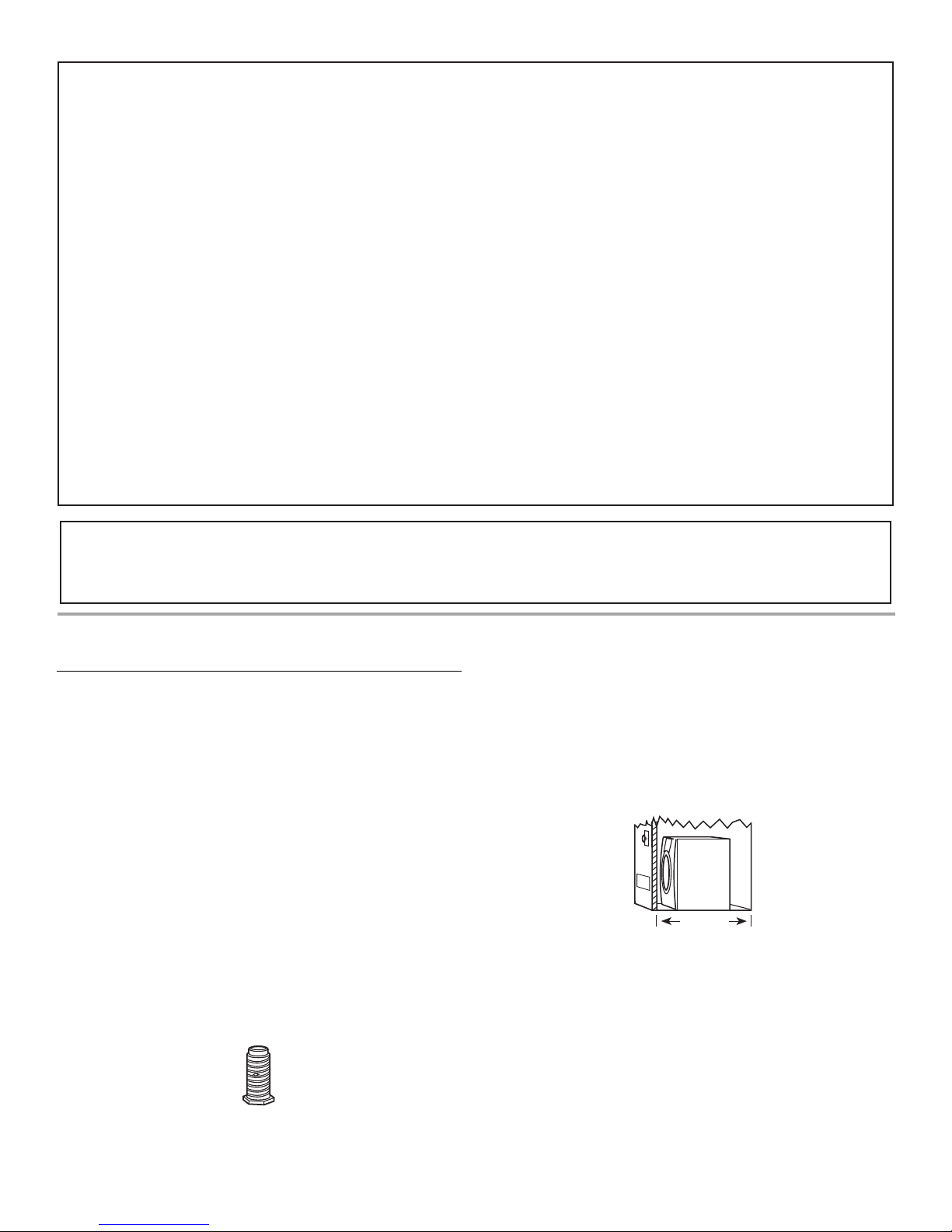
Amana W10216187A User manual

ELECTRONIC
GAS DRYER
Use & Care Guide
For questions about features, operation/performance,
parts, accessories or service, call: 1-800-688-9900
or visit our website at...
www.amana.com
Table of Contents ................................................. 2
W10216187A

2
TABLE OF CONTENTS
DRYER SAFETY..............................................................................2
INSTALLATION INSTRUCTIONS ..................................................4
Tools and Parts ............................................................................4
Optional Pedestal.........................................................................5
Location Requirements ...............................................................5
Electrical Requirements ...............................................................7
Gas Supply Requirements ...........................................................7
Venting Requirements..................................................................8
Plan Vent System .........................................................................9
Install Vent System.....................................................................11
Install Leveling Legs...................................................................11
Level Dryer .................................................................................11
Make Gas Connection ...............................................................11
Connect Vent..............................................................................12
Reverse Door Swing ..................................................................12
Complete Installation .................................................................13
DRYER USE ..................................................................................14
Starting Your Dryer.....................................................................14
Stopping Your Dryer ..................................................................15
Pausing or Restarting.................................................................15
Control Locked...........................................................................15
Drying and Cycle Tips ............................................................... 15
Status Lights.............................................................................. 16
Cycles ........................................................................................ 16
Options ...................................................................................... 17
Modifiers.................................................................................... 18
Changing Cycles, Options, and Modifiers ................................ 18
End of Cycle Signal ................................................................... 19
Drying Rack Options ................................................................. 19
DRYER CARE.............................................................................. 20
Cleaning the Dryer Location...................................................... 20
Cleaning the Lint Screen........................................................... 20
Cleaning the Dryer Interior ........................................................ 20
Removing Accumulated Lint..................................................... 20
Vacation and Moving Care........................................................ 20
Changing the Drum Light .......................................................... 21
TROUBLESHOOTING ................................................................. 21
Dryer Operation ......................................................................... 21
Dryer Results ............................................................................. 22
ASSISTANCE OR SERVICE ........................................................ 23
WARRANTY ................................................................................. 24
You can be killed or seriously injured if you don't immediately
You
can be killed or seriously injured if you don't follow
All safety messageswill tell you what the potential hazard is, tell you how to reduce the chance of injury, and tell you what can
happen if the instructionsare not followed.
Your safety and the safety of others are very important.
We have provided many important safety messagesin thismanual and on your appliance. Alwaysread and obey all safety
messages.
Thisisthe safety alert symbol.
Thissymbol alertsyou to potential hazardsthat can kill or hurt you and others.
All safety messageswill follow the safety alert symbol and either the word “DANGER” or “WARNING.”
These wordsmean:
follow instructions.
instructions.
DANGER
WARNING
DRYER SAFETY

WARNING: For your safety, the information in this manual must be followedto minimize
the risk of re or explosion, or to prevent property damage, personal injury, or death.
– Do not store or use gasoline or other ammable vapors andliquids in the vicinity of this
or any other appliance.
– WHAT TO DO IF YOU SMELL GAS:
•Do not try to light any appliance.
•Do not touch any electrical switch; do not use any phone in your building.
•Immediately call your gas supplier from a neighbor's phone. Follow the gas supplier's
instructions.
•If you cannot reach your gas supplier, call the re department.
– Installation andservice must be performedby a qualiedinstaller, service agency, or
the gas supplier.
•Clear the room, building, or area of all occupants.
WARNING: Gasleakscannot alwaysbe detected by smell.
Gassuppliersrecommend that you use a gasdetector approved by UL or CSA.
For more information, contact your gassupplier.
If a gasleak isdetected, follow the “What to do if you smell gas” instructions.
In the State of Massachusetts, the following installation instructionsapply:
■
Installationsand repairsmust be performed by a qualied or licensed contractor, plumber, or gastter qualied or licensed by
the State of Massachusetts.
■
If using a ball valve, it shall be a T-handle type.
■
A exible gasconnector, when used, must not exceed 3 feet.
3

IMPORTANT SAFETY INSTRUCTIONS
To reduce the risk of re, electric shock, or injury to personswhen using the dryer, follow basic precautions,
including the following:
WARNING:
■Read all instructionsbefore using the dryer.
■Do not place itemsexposed to cooking oilsin your dryer.
Itemscontaminated with cooking oilsmay contribute to
a chemical reaction that could cause a load to catch re.
■Do not dry articlesthat have been previously cleaned in,
washed in, soaked in, or spotted with gasoline, dry-
cleaning solvents, or other ammable or explosive
substancesasthey give off vaporsthat could ignite or
explode.
■Do not allow children to play on or in the dryer. Close
supervision of children isnecessary when the dryer is
used near children.
■Before the dryer isremoved from service or discarded,
remove the door to the drying compartment.
■Do not reach into the dryer if the drum ismoving.
■Do not repair or replace any part of the dryer or attempt
any servicing unless specically recommended in this
Use and Care Guide or in published user-repair
instructionsthat you understand and have the skillsto
carry out.
■Do not use fabric softenersor productsto eliminate static
unless recommended by the manufacturer of the fabric
softener or product.
■Do not use heat to dry articlescontaining foam rubber or
similarly textured rubber-like materials.
■Clean lint screen before or after each load.
■Keep area around the exhaust opening and adjacent
surrounding areasfree from the accumulation of lint, dust,
and dirt.
SAVE THESE INSTRUCTIONS
■The interior of the dryer and exhaust vent should be
cleaned periodically by qualied service personnel.
■Do not install or store the dryer where it will be exposed
to the weather.
■Do not tamper with controls.
■See installation instructionsfor grounding requirements.
IMPORTANT: The gasinstallation must conform with local codes, or in the absence of local codes, with the National Fuel Gas
Code, ANSI Z223.1/NFPA 54 or the Canadian Natural Gasand Propane Installation Code, CSA B149.1.
The dryer must be electrically grounded in accordance with local codes, or in the absence of local codes, with the National
Electrical Code, ANSI/NFPA 70 or Canadian Electrical Code, CSA C22.1.
4
INSTALLATION INSTRUCTIONS
Tools and Parts
Gather the required tools and parts before starting installation.
Read and follow the instructions provided with any tools listed
here.
■8" or 10" pipe wrench
■8" or 10" adjustable wrench
(for gas connections)
■Flat-blade screwdriver
■Adjustable wrench that
opens to 1" (25.4 mm) or
hex-head socket wrench
(for adjusting dryer feet)
■¼" nut driver or socket
wrench
■Level
■Vent clamps
■Knife
■Pipe-joint compound
resistant to LP gas
■Caulking gun and
compound (for installing
new exhaust vent)
■Pliers
■Tape measure
Parts supplied
Remove parts package from dryer drum. Check that all parts are
included.
4 Leveling legs
NOTE: Do not use leveling legs if installing the dryer on a
pedestal.
Parts needed
Check local codes and with gas supplier. Check existing gas
supply, electrical supply, and venting. Read “Electrical
Requirements,” “Gas Supply Requirements,” and “Venting
Requirements” before purchasing parts.
■For close-clearance installations between 31.5" (800.1 mm)
and 37" (939.8 mm), see “Plan Vent System” section for
venting requirements.
37"
(939.8 mm)
Mobile home installations require metal exhaust system hardware
available for purchase from the dealer from whom you purchased
your dryer. For further information, please refer to the “Assistance
or Service” section.
■Mobile Home Installation Kit. Ask for Part Number 346764.
■Metal exhaust system hardware.

5
Optional Pedestal
Are you placing the dryer on a pedestal? You have the option of
purchasing pedestals of different heights separately for this dryer.
You may select a 10" (254 mm) pedestal or a 15.5" (394 mm)
pedestal with a storage drawer. The pedestal will add to the total
height of the dryer for a total height of approximately
46" (1168 mm) or 51.5" (1308 mm), respectively.
For a garage installation, you will need to place the 10" (254 mm)
pedestal at least 9" (229 mm) above the floor. You will need to
place the 15.5" (394 mm) pedestal at least 3" (76 mm) above the
floor.
Optional pedestal (15.5" [394 mm] model shown)
To order, call the dealer from whom you purchased your dryer or
refer to the “Assistance or Service” section.
Pedestal Height Color Part Number
10"(254 mm) White WHP1000SQ
15.5"(394 mm) White XHP1550VW
15.5"(394 mm) Burgundy XHP1550VM
Location Requirements
You will need
■A location that allows for proper exhaust installation. A gas
dryer must be exhausted to the outdoors. See “Venting
Requirements.”
■A grounded electrical outlet located within 2 ft (610 mm) of
either side of the dryer. See “Electrical Requirements.”
■A sturdy floor to support the total dryer weight of 200 lbs
(90.7 kg). The combined weight of a companion appliance
should also be considered.
■A level floor with a maximum slope of 1" (25 mm) under entire
dryer. (If slope is greater than 1" [25 mm], install Extended
Dryer Feet Kit, Part No. 279810.) Clothes may not tumble
properly and automatic sensor cycles may not operate
correctly if dryer is not level.
■For a garage installation, you will need to place the dryer
at least 18" (460 mm) above the floor. If using a pedestal, you
will need 18" (460 mm) to the bottom of the dryer.
Do not operate your dryer at temperatures below 45ºF (7ºC).
At lower temperatures, the dryer might not shut off at the end of
an automatic cycle. Drying times can be extended.
The dryer must not be installed or stored in an area where it will
be exposed to water and/or weather.
Check code requirements. Some codes limit, or do not permit,
installation of the dryer in garages, closets, mobile homes, or
sleeping quarters. Contact your local building inspector.
NOTE: No other fuel-burning appliance can be installed in the
same closet as a dryer.
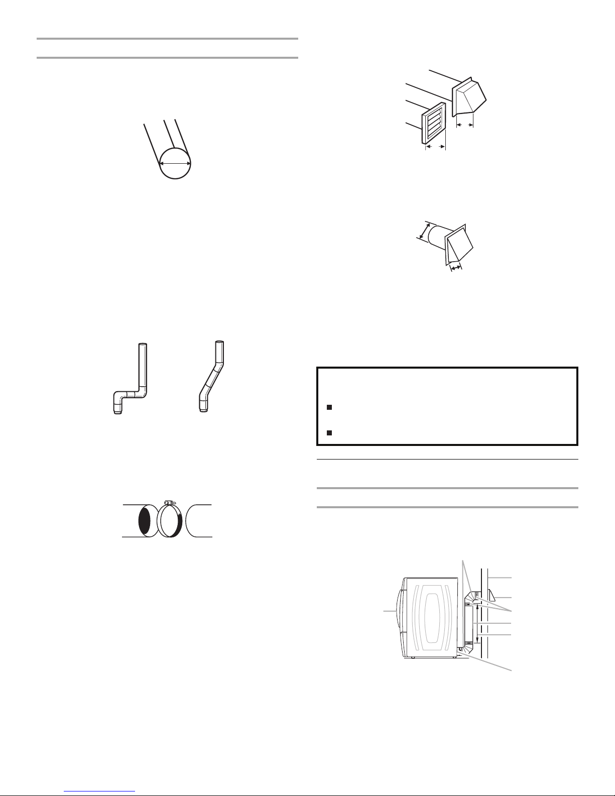
Installation clearances
The location must be large enough to allow the dryer door to
open fully.
Dryer Dimensions
38"
(965.2 mm)
*31½"
(800.1 mm) 27"
(686 mm)
50½"
(1282.7 mm)
*Most installations require a minimum 5" (127 mm) clearance
behind the dryer for the exhaust vent with elbow. See “Venting
Requirements.”
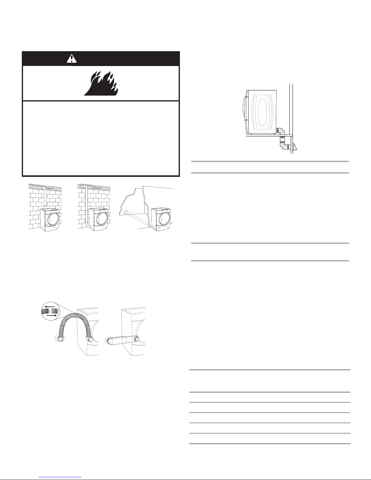
Installation spacing for recessedarea or closet installation
The following spacing dimensions are recommended for this
dryer. This dryer has been tested for spacing of 0" (0 mm)
clearance on the sides and rear. Recommended spacing should
be considered for the following reasons:
■Additional spacing should be considered for ease of
installation and servicing.
■Additional clearances might be required for wall, door, and
floor moldings.
■Additional spacing should be considered on all sides of the
dryer to reduce noise transfer.
■For closet installation, with a door, minimum ventilation
openings in the top and bottom of the door are required.
Louvered doors with equivalent ventilation openings are
acceptable.
■Companion appliance spacing should also be considered.
Custom undercounter installation - Dryer only
0"
(0 mm)
38" min.
(965.2 mm)
1"*
(25 mm)
1"*
(25 mm)
27"
(686 mm)
*Required spacing

6
Closet installation - Dryer only
AB
14" max.*
(356 mm)
18" min.*
(457.2 mm)
48 in.
2*
(3100 mm
2
)
24 in.
2*
(1550 mm
2
)
5"**
(127 mm)
1"*
(25 mm)
31½"
(800 mm)
3"*
(76 mm)
3"*
(76 mm)
A. Side view - closet or confined area
B. Closet door with vents
*Required spacing
**For side or bottom venting, 0" (0 mm) spacing is allowed.
Recessedor closet installation - Dryer on pedestal
AB
1"
(25 mm)
(25 mm)
27"
(686 mm)
31½"
(800 mm)
18" min.*
(457.2 mm)
14" max.*
(356 mm)
5"
(127 mm)
**
1"*
1"
(25 mm)
A. Recessed area
B. Side view - closet or confined area
*Required spacing
**For side or bottom venting, 0" (0 mm) spacing is allowed.
Installation spacing for cabinet installation
■For cabinet installation, with a door, minimum ventilation
openings in the top of the cabinet are required.
7"* (178 mm)
9"*
(229 mm)
7"* (178 mm)
5"**
(127 mm)
31½"
(800 mm)
27"
(686 mm)
1"*
(25 mm) (25 mm)
1"
(25 mm)
1"
*Required spacing
**For side or bottom venting, 0" (0 mm) spacing is allowed.
Recommendedinstallation spacing for recessedor
closet installation, with stackedwasher anddryer
The dimensions shown are for the recommended spacing.
48 in.
2
*
(31000 mm
2
)
3"* (76 mm)
3"* (76 mm)
1"* (25 mm)
24 in.
2
*
(15500 mm
2
)
*Required spacing
6"* (152 mm)
76"
(1930 mm)
27"
(686 mm)
1"
(25 mm)
1"
(25 mm)
5½"**
(140 mm)
*Required spacing
**For side or bottom venting, 0" (0 mm) spacing is allowed.
Mobile home - additional installation requirements
This dryer is suitable for mobile home installations.
The installation must conform to the Manufactured Home
Construction and Safety Standard, Title 24 CFR, Part 3280
(formerly the Federal Standard for Mobile Home Construction
and Safety, Title 24, HUD Part 280).
Mobile home installations require:
■Metal exhaust system hardware, which is available for
purchase from your dealer.
■Mobile Home Installation Kit Part Number 346764. See “Tools
and Parts” section for information on ordering.
■Special provisions must be made in mobile homes to
introduce outside air into the dryer. The opening (such as a
nearby window) should be at least twice as large as the dryer
exhaust opening.

7
Electrical Requirements
Electrical Shock Hazard
Pluginto a grounded 3prongoutlet.
Do not remove ground prong.
Do not use an adapter.
Do not use an extension cord.
Failure to follow these instructions can result in death,
re, or electrical shock.
WARNING
■120 Volt, 60 Hz., AC only, 15- or 20-amp fused electrical
supply is required. A time-delay fuse or circuit breaker is
recommended. It is also recommended that a separate circuit
serving only this dryer be provided.
GROUNDINGINSTRUCTIONS
SAVE THESE INSTRUCTIONS
■For a grounded, cord-connected dryer:
Thisdryer must be grounded. In the event of malfunction or
breakdown, grounding will reduce the risk of electric shock
by providing a path of least resistance for electric current.
Thisdryer isequipped with a cord having an
equipment-grounding conductor and a grounding plug. The
plug must be plugged into an appropriate outlet that is
properly installed and grounded in accordance with all local
codesand ordinances.
WARNING:Improper connection of the
equipment-grounding conductor can result in a risk of
electric shock. Check with a qualied electrician or service
representative or personnel if you are in doubt asto
whether the dryer isproperly grounded. Do not modify the
plug provided with the dryer: if it will not t the outlet, have
a proper outlet installed by a qualied electrician.
Gas Supply Requirements
WARNING
Explosion Hazard
Use a new CSA International approved gas supply line.
Install a shut-off valve.
Securely tighten all gas connections.
If connected to LP, have a qualied person make sure
gas pressure does not exceed 13" (330 mm) water
column.
Examples of a qualied person include:
licensed heatingpersonnel,
authorized gas company personnel, and
authorized service personnel.
Failure to do so can result in death, explosion, or re.
Gas Type
Natural gas:
This dryer is equipped for use with Natural gas. It is design-
certified by CSA International for LP (propane or butane) gases
with appropriate conversion.
■Your dryer must have the correct burner for the type of gas in
your home. Burner information is located on the rating plate
in the door well of your dryer. If this information does not
agree with the type of gas available, contact your dealer or
call the phone numbers referenced in the “Assistance or
Service” section.
LP gas conversion:
Conversion must be made by a qualifiedtechnician.
No attempt shall be made to convert the appliance from the gas
specified on the model/serial rating plate for use with a different
gas without consulting your gas company.
Gas supply line
■Must include 1/8" NPT minimum plugged tapping accessible
for test gauge connection, immediately upstream of the gas
connection to the dryer (see illustration).
■½" IPS pipe is recommended.
■3/8" approved aluminum or copper tubing is acceptable for
lengths under 20 ft (6.1 m) if local codes and gas supplier
permit.
■If you are using Natural gas, do not use copper tubing.
■Lengths over 20 ft (6.1 m) should use larger tubing and a
different size adapter fitting.

8
■If your dryer has been converted to use LP gas, 3/8" LP
compatible copper tubing can be used. If the total length of
the supply line is more than 20 ft (6.1 m), use larger pipe.
NOTE: Pipe-joint compounds that resist the action of LP gas
must be used. Do not use TEFLON®† tape.
■Must include a shutoff valve:
An individual shutoff valve must be installed within
6 feet (1.8 m) of the dryer in accordance with the National
Fuel Gas Code, ANSI Z223.1. The location should be easy to
reach for opening and closing.
A
B
E
D
C
A. 3/8" flexible gas connector
B. 3/8" pipe to flare adapter fitting
C. 1/8" NPT minimum plugged tapping
D. 1/2" NPT gas supply line
E. Gas shutoff valve
Gas supply connection requirements
■Use an elbow and a 3/8" flare x 3/8" NPT adapter fitting
between the flexible gas connector and the dryer gas pipe, as
needed to avoid kinking.
■Use only pipe-joint compound. Do not use TEFLON®† tape.
■This dryer must be connected to the gas supply line with a
listed flexible gas connector that complies with the standard
for connectors for gas appliances, ANSI Z21.24.
Burner input requirements
Elevations up to 10,000 ft (3,048 m):
■The design of this dryer is certified by CSA International for
use at altitudes up to 10,000 ft (3,048 m) above sea level at
the Btu rating indicated on the model/serial number plate.
Burner input adjustments are not required when the dryer is
operated up to this elevation.
Elevations above 10,000 ft (3,048 m):
■When installed above 10,000 ft (3,048 m) a 4% reduction of
the burner Btu rating shown on the model/serial number plate
is required for each 1,000 ft (305 m) increase in elevation.
Gas supply pressure testing
■The dryer must be disconnected from the gas supply piping
system during pressure testing at pressures greater than
½ psi.
Dryer gas pipe
■The gas pipe that comes out through the rear of your dryer
has a 3/8" male pipe thread.
A
B
*6¼"
(159 mm)
1½"
(38 mm)
A. ½" NPT gas supply line
B. 3/8" NPT dryer pipe
■*NOTE: If the dryer is mounted on a pedestal, the gas pipe
height must be an additional 10" (254 mm) or 15.5" (394 mm)
from the floor, depending on the pedestal model. For a
garage installation, the gas pipe height must be an additional
18" (460 mm) from the floor.
Venting Requirements
WARNING
Fire Hazard
Use a heavy metal vent.
Do not use a plastic vent.
Do not use a metal foil vent.
Failure to follow these instructions can result in death
or re.
WARNING: To reduce the risk of fire, this dryer MUST BE
EXHAUSTED OUTDOORS.
IMPORTANT: Observe all governing codes and ordinances.
The dryer exhaust must not be connected into any gas vent,
chimney, wall, ceiling, attic, crawlspace, or a concealed space of
a building.
If using an existing vent system
■Clean lint from the entire length of the system and make sure
exhaust hood is not plugged with lint.
■Replace any plastic or metal foil vent with rigid metal vent.
■Review Vent system chart. Modify existing vent system if
necessary to achieve the best drying performance.

9
If this is a new vent system
Vent material
■Use a heavy metal vent. Do not use plastic or metal foil vent.
■4" (102 mm) heavy metal exhaust vent and clamps must be
used. DURASAFE™ venting products are recommended.
4" (102 mm) heavy metal exhaust vent
4"
102 mm
DURASAFE™ vent products can be purchased from your
dealer or by calling Whirlpool Parts and Accessories. For
more information, see the “Assistance or Service” section.
Rigidmetal vent
■For best drying performance, rigid metal vents are
recommended.
■Rigid metal vent is recommended to avoid crushing and
kinking.
Elbows
45° elbows provide better airflow than 90° elbows.
Good Better
Clamps
■Use clamps to seal all joints.
■Exhaust vent must not be connected or secure with screws or
other fastening devices that extend into the interior of the
duct and catch lint. Do not use duct tape.
Clamp
†®TEFLON is a registered trademark of E.I. Du Pont De Nemours and Company.
Exhaust
Recommended hood styles are shown here.
4"
(102 mm)
4"
(102 mm)
B
A
A. Louvered hood style
B. Box hood style
The angled hood style (shown here) is acceptable.
4"
(102 mm)
2½"
(63.5 mm)
■An exhaust hood should cap the vent to keep rodents and
insects from entering the home.
■Exhaust hood must be at least 12" (305 mm) from the ground
or any object that may be in the path of the exhaust (such as
flowers, rocks or bushes, snow line, etc.).
■Do not use an exhaust hood with a magnetic latch.
Improper ventingcan cause moisture and lint to collect
indoors, which may result in:
Moisture damage to woodwork, furniture, paint, wallpaper,
carpets, etc.
Housecleaning problemsand health problems.
Plan Vent System
Choose your exhaust installation type
Recommendedexhaust installations
Typical installations vent the dryer from the rear of the dryer.
Other installations are possible.
H
G
F
E
D
C
A
B
A. Dryer
B. Elbow
C. Wall
D. Exhaust hood
E. Clamps
F. R i g i d m e t a l v e n t
G. Vent length necessary to connect elbows
H. Exhaust outlet

10
Optional exhaust installations
This dryer can be converted to exhaust out the right side, left
side, or through the bottom. Contact your local dealer to have the
dryer converted.
WARNING
Fire Hazard
Cover unused exhaust holes with one of the
followingkits:
279818 (white)
W10186596 (midnight grey)
Contact your local dealer.
Failure to follow these instructions can result in death,
re, electrical shock, or serious injury.
ABC
A. Standard rear offset exhaust installation
B. Left or right side exhaust installation
C. Bottom exhaust installation (not an option
with pedestal installations)
Alternate installations for close clearances
Venting systems come in many varieties. Select the type best for
your installation. Two close-clearance installations are shown.
Refer to the manufacturer’s instructions.
AB
A. Over-the-top installation (also available with one offset elbow)
B. Periscope installation
NOTE: The following kits for close clearance alternate
installations are available for purchase. To order, please see
the “Assistance or Service” section.
■Over-the-Top Installation:
Part Number 4396028
■Periscope Installation (For use with dryer vent to wall vent
mismatch):
Part Number 4396037 - 0" (0 mm) to 18" (457.2 mm)
mismatch
Part Number 4396011 - 18" (457.2 mm) to 29" (736.6 mm)
mismatch
Part Number 4396014 - 29" (736.6 mm) to 50" (1270 mm)
mismatch
Special provisions for mobile home installations
The exhaust vent must be securely fastened to a noncombustible
portion of the mobile home structure and must not terminate
beneath the mobile home. Terminate the exhaust vent outside.
Determine vent path
■Select the route that will provide the straightest and most
direct path outdoors.
■Plan the installation to use the fewest number of elbows and
turns.
■When using elbows or making turns, allow as much room
as possible.
■Bend vent gradually to avoid kinking.
■Use the fewest 90° turns possible.
Determine vent length andelbows neededfor best
drying performance
■Use the following Vent system chart to determine type of vent
material and hood combinations acceptable to use.
■NOTE: Do not use vent runs longer than those specified in
the Vent system chart. Exhaust systems longer than those
specified will:
■Shorten the life of the dryer.
■Reduce performance, resulting in longer drying times and
increased energy usage.
The Vent system chart provides venting requirements that will
help to achieve the best drying performance.
Vent system chart
NOTE: Side and bottom exhaust installations have a 90º turn
inside the dryer. To determine maximum exhaust length, add one
90º turn to the chart.
Number of
90º turns
or elbows
Type of vent Box or
Louvered
hoods
Angled
hoods
0Rigidmetal 64 ft (20 m) 58 ft (17.7 m)
1Rigidmetal 54 ft (16.5 m) 48 ft (14.6 m)
2Rigidmetal 44 ft (13.4 m) 38 ft (11.6 m)
3Rigidmetal 35 ft (10.7 m) 29 ft (8.8 m)
4Rigidmetal 27 ft (8.2 m) 21 ft (6.4 m)

11
Install Vent System
1. Install exhaust hood. Use caulking compound to seal exterior
wall opening around exhaust hood.
2. Connect vent to exhaust hood. Vent must fit inside exhaust
hood. Secure vent to exhaust hood with 4" (102 mm) clamp.
3. Run vent to dryer location. Use the straightest path possible.
See “Determine vent path” in “Plan Vent System.” Avoid 90º
turns. Use clamps to seal all joints. Do not use duct tape,
screws, or other fastening devices that extend into the
interior of the vent to secure vent. Items sticking through the
vent can catch lint.
Install Leveling Legs
WARNING
Excessive Weight Hazard
Use two or more people to move and install dryer.
Failure to do so can result in back or other injury.
1. To protect the floor, use a large flat piece of cardboard from
the dryer carton. Place cardboard under the entire back edge
of the dryer.
2. Firmly grasp the body of the dryer (not the console panel).
Gently lay the dryer on the cardboard. See illustration.
3. Examine the leveling legs. Find the diamond marking.
4. Screw the legs into the leg holes by hand. Use a wrench to
finish turning the legs until the diamond marking is no longer
visible.
5. Place a carton corner post from dryer packaging under each
of the 2 dryer back corners. Stand the dryer up. Slide the
dryer on the corner posts until it is close to its final location.
Leave enough room to connect the exhaust vent.
For mobile home use
Gas dryers must be securely fastened to the floor at the time of
installation.
Mobile home installations require a Mobile Home Installation Kit.
For more information, please reference the service numbers in
the “Assistance or Service” section.
Level Dryer
Check the levelness of the dryer. Check levelness first side to
side, then front to back.
If the dryer is not level, prop up the dryer using a wood block.
Use a wrench to adjust the legs up or down and check again
for levelness.
Make Gas Connection
1. Remove the red cap from the gas pipe.
2. Using a wrench to tighten, connect the gas supply to the
dryer. Use pipe-joint compound on the threads of all non-
flared male fittings. If flexible metal tubing is used, be sure
there are no kinks.
AB
A. Flared male fitting
B. Non-flared male fitting
NOTE: For LP gas connections, you must use pipe-joint
compound resistant to the action of LP gas. Do not use
TEFLON®†
†®TEFLON is a registered trademark of E.I. Du Pont De Nemours and Company.
tape.

12
A combination of pipe fittings must be used to connect the
dryer to the existing gas line. Shown is a recommended
connection. Your connection may be different, according to
the supply line type, size, and location.
A. 3/8" flexible gas connector
B. 3/8" dryer pipe
C. 3/8" to 3/8" pipe elbow
D. 3/8" pipe-to-flare adapter fitting
A
BC
D
3. Open the shutoff valve in the supply line. The valve is open
when the handle is parallel to the gas pipe.
A. Closed valve
B. Open valve
A
B
4. Test all connections by brushing on an approved
noncorrosive leak-detection solution. Bubbles will show a
leak. Correct any leak found.
Connect Vent
1. Using a 4" (102 mm) clamp, connect vent to exhaust outlet
in dryer. If connecting to existing vent, make sure the vent is
clean. The dryer vent must fit over the dryer exhaust outlet
and inside the exhaust hood. Check that the vent is secured
to exhaust hood with a 4" (102 mm) clamp.
2. Move dryer into its final location. Do not crush or kink vent.
3. (On gas models) Check that there are no kinks in the flexible
gas line.
4. Once the exhaust vent connection is made, remove the
corner posts and cardboard.
Reverse Door Swing
You can change your door swing from a right-side opening to a
left-side opening, if desired.
NOTE: For ease of installation, you may want to use 2 or more
people to remove and reattach the dryer door.
Remove the door
1. Place a towel or soft cloth on top of the dryer or work space
to protect the surface.
2. Open the dryer door. Remove the 5 screws that hold the door
hinge on the front panel of the dryer.
A
B
C
A. Dryer front panel
B. Dryer door
C. Screws
3. Remove the door.
4. Lay the dryer door on a flat, protected surface with the inside
door assembly facing up.
Remove the 5 screws to release the outer door assembly
from the inner door assembly, as indicated below. It is
important that you remove only the 5 indicated screws.
5. Lift the inner door assembly off of the outer door assembly.
Set the outer door assembly aside.
Reverse the hinge
1. Place the inner door, screw head side up, on the work space.
2. Remove the 4 hinge screws that hold the hinge to the door
and remove hinge.
A
A
B
B
C
C
A. Hinge side screw
B. Locator pins on hinge
C. Top side screw

13
3. Move the large hole screw to the opposite side. Remove the
2 plug screws and plastic plugs, and insert them in the
original screw holes on the opposite side.
A. Hinge screws
B. Large hole screw
C. Plug screws and plastic plugs
AC
B
4. Move hinge to the other side and reattach with the 4 screws
removed in Step 2. Make sure locator pins line up in holes
and drive the top 2 screws in place first to help drive locator
pins into proper location.
5. Set the inner door assembly aside.
Reverse the door handle
1. Place the outer door assembly face down on work space.
2. Remove the 6 screws that hold the intermediate door to the
outer door assembly. Remove the intermediate door, and set
hinge shield aside. Remove the hinge hole cover.
A. Intermediate door
B. Hinge shield
C. Hinge hole cover
B
A
C
3. Rotate the window assembly 180º and reattach the
intermediate door, hinge shield, and hinge hole cover
with the 6 screws removed in Step 2.
Reinstalling the door
1. Place the inner door assembly into the outer door assembly.
To fit correctly, the inside door assembly edge is completely
inside the outside door assembly edge.
2. Reassemble the inner and outer door assemblies with the
5 screws.
3. Remove existing label from the opposite side of the door and
discard. Find label provided with the Use and Care Guide and
apply over original hinge holes.
4. Align the door by placing the locating tabs on the hinge with
the locating holes on the dryer front panel. Insert and tighten
the center hinge screw. The door will hang in place while you
insert and tighten the remaining 4 screws.
NOTE: Two or more people may be needed to reattach the
dryer door.
B
C
A
A. Dryer door
B. Dryer front panel
C. Insert this hinge screw first.
5. Close the door and check that it latches securely.
6. Check for fingerprints on the glass. Clean the glass if
necessary.
Complete Installation
1. Check that all parts are now installed. If there is an extra part,
go back through the steps to see which step was skipped.
2. Check that you have all of your tools.
3. Check the dryer’s final location. Be sure the vent is not
crushed or kinked.

14
4. Check that the dryer is level. See “Level Dryer.”
Electrical Shock Hazard
Pluginto a grounded 3prongoutlet.
Do not remove ground prong.
Do not use an adapter.
Do not use an extension cord.
Failure to follow these instructions can result in death,
re, or electrical shock.
WARNING
5. Plug into a grounded 3 prong outlet. Turn on power.
6. Remove any protective film or tape remaining on the dryer.
7. Dispose of/recycle all packaging materials.
8. Read “Dryer Use.”
9. Wipe the dryer drum interior thoroughly with a damp cloth to
remove any dust.
10. Select a Timed Dry heated cycle, and start the dryer. Do not
select the Air Dry Temperature setting.
If the dryer will not start, check the following:
■Controls are set in a running or “On” position.
■Start button has been pushed firmly.
■Dryer is plugged into a grounded 3 prong outlet.
■Electrical supply is connected.
■Household fuse is intact and tight, or circuit breaker has
not tripped.
■Dryer door is closed.
11. When the dryer has been running for 5 minutes, open the
dryer door and feel for heat. If you feel heat, cancel cycle and
close door. If you do not feel heat, turn off the dryer and
check that the gas supply line shutoff valve is open.
■If the gas supply line shutoff valve is closed, open it, then
repeat the 5-minute test as outlined above.
■If the gas supply line shutoff valve is open, contact a
qualified technician.
DRYER USE
Starting Your Dryer
WARNING
Explosion Hazard
Keep ammable materials and vapors, such as
gasoline, away from dryer.
Do not dry anythingthat has ever had anything
ammable on it (even after washing).
Failure to follow these instructions can result in death,
explosion, or re.
WARNING
Fire Hazard
No washer can completely remove oil.
Do not dry anythingthat has ever had any type of oil on
it (includingcookingoils).
Items containingfoam, rubber, or plastic must be dried
on a clothesline or by usingan Air Cycle.
Failure to follow these instructions can result in death
or re.
WARNING: To reduce the risk of fire, electric shock, or injury to
persons, read the IMPORTANT SAFETY INSTRUCTIONS before
operating this appliance.
Follow these basic steps to start your dryer. Please refer to
specific sections of this manual for more detailed information.
1. Clean lint screen before each load. See “Cleaning the Lint
Screen.”

15
2. Place laundry in dryer and shut door.
3. Press the POWER button. Then rotate the dial or press a
Timed Cycles button to select the desired Automatic or
Timed Cycle. The indicator light for the selected Automatic or
Timed cycle will glow green. The preset modifiers for the
selected cycle will glow green. Selectable options will glow
amber. If an option or modifier is unavailable with the selected
cycle, the light will not illuminate. The estimated or actual
cycle time
(in minutes) will show in the display.
To use an Automatic Cycle
NOTE: A light next to each feature will glow green when the
feature is selected or will glow amber when the feature is
selectable. The light will not glow when the selection is
unavailable with the cycle or option combinations selected.
■Select an Automatic Cycle.
■Select DRYNESS LEVEL to adjust how dry you want the
load. As the cycle runs, the control senses the dryness of
the load and adjusts the time automatically for the
selected dryness level.
NOTE: Most loads may be dried using Normal dryness
level, which is shown in bold letters on your control panel.
Normal is the energy preferred dryness level and will use
the least energy.
■Select the desired Options.
To make changes during an Automatic Cycle:
■Press STOP once.
■Adjust Dryness Level.
NOTE: Dryness Level selections can be made only while
using Automatic Cycles. You can select a different
dryness level, depending on your load, by pressing
Dryness Level and choosing More Dry, Normal, or Less
Dry. Selecting More Dry, Normal, or Less Dry
automatically adjusts the sensed time needed.
How Automatic Cycles work
The AccelerCare function improves drying performance with Auto
Moisture Sensing Plus, which advances the cycle as moisture is
extracted from clothing. A thermistor (electronic temperature
sensor) and moisture sensing strips in the dryer drum help
measure the amount of moisture in the clothes as they tumble.
An electronic control determines the load type to help save time,
avoid overdrying, and increase the accuracy of the end dryness
level. After the first 5 minutes of an automatic cycle, the
estimated time display will adjust based on the approximate load
size, cycle, dryness level selected, and amount of moisture left in
the clothes. When the clothes have reached approximately 80%
of the dryness level selected, the estimated time display will
adjust again, showing the final drying time. Auto Moisture
Sensing Plus takes the guesswork out of drying time and
enhances fabric care.
To use a TimedCycle
NOTE: A light next to each feature will glow green when the
feature is selected or will glow amber when the feature is
selectable. The light will not glow when the selection is
unavailable with the cycle or option combinations selected.
■Press a Timed Cycles button or, to select Air Fluff, rotate
the control knob to the desired cycle.
■Press MORE TIME or LESS TIME until the desired drying
time is displayed. Tap MORE TIME or LESS TIME, and the
time will change by 1-minute intervals. Press and hold
MORE TIME or LESS TIME, and the time will change by
5-minute intervals.
NOTE: The More Time and Less Time buttons can be
used only with Timed Cycles.
■Press TEMPERATURE until the desired temperature
glows.
NOTE: During a Timed Cycle, you can change the settings for
Time, Temperature, Wrinkle Prevent, and End of Cycle Signal.
Press STOP twice to stop the dryer and clear the settings.
Select another cycle or option.
4. (OPTIONAL STEP) If desired, select OPTIONS. For more
details, see “Options.”
5. (OPTIONAL STEP) If desired, set the
End of Cycle Signal
.
Select LOUD or SOFT by pressing the Cycle Signal button
to alert you when a cycle ends.
6. Press and hold START for approximately 3 seconds until
dryer starts. Be sure the door is closed.
■If you do not press Start within 5 minutes of selecting the
cycle, the dryer automatically shuts off.
■If you wish to end your drying cycle after pressing Start,
press Stop twice.
Stopping Your Dryer
To stop your dryer at any time
Press STOP twice or open the door.
Pausing or Restarting
To pause the dryer at any time
Open the door or press STOP once.
To restart the dryer
Close the door. Press and hold START until dryer starts.
NOTE: Drying will continue from where the cycle was interrupted
if you close the door and press START within 5 minutes. If the
cycle is interrupted for more than 5 minutes, the dryer will shut
off. Select new cycle settings before restarting the dryer.
Control Locked
This feature allows you to lock your settings to avoid unintended
use of the dryer. You can also use the Control Locked feature to
avoid unintended cycle or option changes during dryer operation.
To ena ble the Control Lockedfeature:
Press and hold CYCLE SIGNAL for 3 seconds. The Control
Locked indicator light glows, and a single beep tone is heard.
To unlock, press and hold CYCLE SIGNAL for 3 seconds.
The indicator light turns off.
Drying and Cycle Tips
Select the correct cycle and dryness level or temperature for your
load. If an Automatic Cycle is running, the display shows the
estimated cycle time, which is determined by your dryer
automatically sensing the dryness level of your load. If a Timed
Cycle is running, the display shows the exact number of minutes
remaining in the cycle.

16
Cool Down tumbles the load without heat during the last few
minutes of all cycles. Cool Down makes the loads easier to
handle and reduces wrinkling. The length of the Cool Down
depends on the load size and dryness level.
Drying tips
■Follow care label directions when they are available.
■If desired, add a fabric softener sheet. Follow package
instructions.
■To reduce wrinkling, remove the load from the dryer as soon
as tumbling stops. This is especially important for permanent
press, knits, and synthetic fabrics.
■Avoid drying heavy work clothes together with lighter fabrics.
This could cause overdrying of lighter fabrics and lead to
increased shrinkage or wrinkling.
Cycle tips
■Dry most loads using the preset cycle settings.
■Refer to the Automatic or Timed Cycles Preset Settings chart
(in the “Cycles” section) for a guide to drying various loads.
■Drying temperature and Dryness Level are preset when
you choose an Automatic Cycle. You can select a
different dryness level, depending on your load, by
pressing Dryness Level and choosing More Dry, Normal,
or Less Dry.
NOTE: You cannot use the Timed Cycle Adjust and you
cannot modify temperature with the Automatic cycles.
■If you wish to adjust the cycle length of a Timed Cycle,
press More Time or Less Time. Adjust the temperature of
a Timed Cycle by pressing TEMPERATURE until the
desired temperature is selected.
NOTE: You cannot use the Dryness Level with Timed
Cycles.
Status Lights
You may follow the progress of your dryer with the drying Status
indicator lights.
TimedCycle
The Timed Cycle light glows green during a Timed Cycle.
Wet
The Wet light glows green at the beginning of Automatic Cycle if
a wet item is detected or in a timed cycle after 5 minutes.
■In an Automatic Cycle, if a wet item is not detected after
5 minutes, the dryer will run for a preset minimum run time
(based on the selected cycle and dryness level setting) and
then go into Cool Down. The Cool Down and Wrinkle Prevent
indicators will glow green, if selected.
■In a Timed Cycle, the Wet light will glow green after 5 minutes
and remain on until the dryer enters Cool Down.
Damp
The Damp light glows green in an Automatic Cycle when the
laundry is approximately 80% dry. This is useful when you want
to remove lightweight items in a mixed load to avoid overdrying
or remove partially dry items that may need ironing. To be alerted
when the load is about 80% dry, you may use the damp dry
signal option. See Damp Dry Signal in “Options.”
Cool Down
The Cool Down light glows green during the cool down part of
the cycle. Laundry cools for ease in handling.
Clothes Dry
The Clothes Dry light glows green when the drying cycle is
finished. This indicator stays on during Wrinkle Prevent.
Wrinkle Prevent
The Wrinkle Prevent light glows green when this option is
selected. This indicator stays on with Clothes Dry.
Sensing/Revising Est. Time
The Sensing/Revising Est. Time light glows green when moisture
sensing strips in the dryer drum are measuring the amount of
moisture in the clothes. The estimated time display may adjust
to show a more accurate drying time.
Indicator lights
Other indicator lights show Cycle, Options, Modifiers, End of
Cycle, and Control Lock settings selected. The display shows
the estimated or actual time remaining.
Cycles
Select the drying cycle that matches the type of load you are
drying. See Automatic Dry chart or Timed Preset Cycle Settings
chart.
Automatic Cycles
Automatic Cycles allow you to match the cycle to the load you
are drying. See the following Automatic Dry Preset Cycle Settings
chart. Each cycle dries certain fabrics at the recommended
temperature. A sensor detects the moisture in the load and
automatically adjusts the drying time for optimal drying.
Heavy Duty
Use this cycle to get high heat for heavyweight mixed loads,
cotton towels, or bedspreads.
Denim
Use this cycle to get medium high heat for drying denims.
Normal
Use this cycle to get medium heat for drying sturdy fabrics such
as work clothes and sheets.
Casual
Use this cycle to get low heat for drying no-iron fabrics, such
as sport shirts, casual business clothes, and permanent press
blends.

17
Delicate
Use this cycle to get extra-low heat to gently dry items such as
lingerie, blouses, or washable knit fabrics.
Automatic Dry Preset Cycle Settings
Automatic Cycles
LoadType
Temperature Time*
(Minutes)
HEAVY DUTY
Heavyweight mixed loads,
cotton towels, bedspreads
High 45
DENIM
Denim jeans, jackets
Medium High 55
NORMAL
Corduroys, work clothes,
sheets
Medium 40
CASUAL
Permanent press,
synthetics
Low 35
DELICATE
Lingerie, blouses, washable
knit fabrics
Extra Low 30
*Estimated Time with Dryness Level (Normal) setting. Time will
vary depending on load type and load size.
TimedCycles
Use Timed Cycles to select a specific amount of drying time and
a drying temperature. (Temperatures are not selectable with Air
Fluff.) When a Timed Cycle is selected, the Estimated Time
Remaining display shows the actual time remaining in your cycle.
You can change the actual time in the cycle by pressing More
Time or Less Time. See “Changing Cycles, Options, and
Modifiers.”
TimedDry
Use this cycle to complete drying if items are still damp after an
Automatic Cycle. Timed Dry is also useful for drying heavyweight
and bulky items, such as bedspreads and work clothes.
Lightweight garments, such as exercise wear, can be dried using
Timed Dry on a low temperature setting.
Quick Dry
Use this cycle for drying small loads or loads that need a short
drying time.
Touch Up
Use this cycle to help smooth out wrinkles from items, such as
clothes packed in a suitcase or items wrinkled from being left in
the dryer too long.
Air Fluff
Rotate the dial to Air Fluff to use this cycle for items that require
drying without heat such as rubber, plastic, and heat-sensitive
fabrics. This table shows examples of items that can be dried
using Air Fluff. The temperature setting is not adjustable with
this cycle.
Type of LoadTime*
(Minutes)
Foam rubber - pillows, padded bras, stuffed toys 20 - 30
Plastic - Shower curtains, tablecloths 20 - 30
Rubber-backed rugs 40 - 50
Olefin, polypropylene, sheer nylon 10 - 20
*Reset cycle to complete drying, if needed.
When using Air Fluff
■Check that coverings are securely stitched.
■Shake and fluff pillows by hand periodically during the cycle.
■Dry item completely. Foam rubber pillows are slow to dry.
TimedPreset Cycle Settings
TimedCycles
LoadType
Default
Temperature
Default Time
(Minutes)
TIMED DRY
Heavyweight, bulky items,
bedspreads, work clothes
High 40
QUICK DRY
Small loads
High 23
TOUCH UP
Helps to smooth out
wrinkles
Medium High 20
AIR FLUFF
Dry without heat
Air Dry
(no heat)
36
*Use the Air Fluff cycle for items that require drying without heat
such as rubber, plastic, and heat-sensitive fabrics.
Options
You can customize your cycles by selecting options. Not all
Options are available with all cycles. Current selections will glow
green. If an option is unavailable with a selected cycle, the light
will not illuminate when pressed and an error sound will be heard.
Wrinkle Prevent
Wrinkle Prevent helps smooth out wrinkles that form when you
cannot unload the dryer promptly at the end of a cycle. During
this option, the dryer stops tumbling and then tumbles again for
a brief period.
■Press WRINKLE PREVENT to get up to 2 hours of heat-free,
periodic tumbling at the end of a cycle.

18
■Stop Wrinkle Prevent at any time by pressing WRINKLE
PREVENT or opening the dryer door.
■For the Casual cycle, Wrinkle Prevent is preset to ON.
The other cycles will retain the Wrinkle Prevent setting.
For example, if you select Wrinkle Prevent in the Normal
cycle, Wrinkle Prevent will be on the next time you select the
Normal cycle.
NOTE: If you do not select Wrinkle Prevent, the dryer stops
after cool down.
Damp Dry Signal
Select the Damp Dry Signal to alert you that your clothes are
approximately 80% dry. This is useful when you want to remove
lightweight items in a mixed load to avoid overdrying or remove
partially dry items that may need ironing.
NOTE: The Damp Dry Signal is available only with the Automatic
Cycles.
Button Sounds
You can change the volume of the sound of the beeps. Press
BUTTON SOUNDS until the desired volume (Loud, Soft, or Off)
glows. The Power and Cancel buttons will still beep softly when
the Button Sounds volume is set to Off.
Drum Light
Press DRUM LIGHT to turn on the light inside the dryer drum.
During a cycle, if Drum Light is selected, the drum light turns on
and will remain on until Drum Light is pressed again, the door is
open and closed, or the door is left open for 5 minutes.
When the dryer is not running, the drum light will turn on when
Drum Light is pressed or the dryer door is opened, and it will
remain on until the dryer door has been open for 5 minutes, the
dryer door is closed or Drum Light is pressed again.
Press DRUM LIGHT at any time to turn the drum light ON or OFF.
Modifiers
Use Modifiers to select time, temperatures, and dryness levels for
the Timed Cycles. Not all Modifiers are available with all options
and cycles. Available modifier settings will glow amber. Current
selections will glow green. If a modifier is unavailable with a
selected cycle, the light will not illuminate.
Time
Press MORE TIME or LESS TIME until the desired drying time is
displayed. The time cannot be changed with Automatic Cycles.
Temperature
Press TEMPERATURE until the desired temperature setting
glows. Temperature modifiers cannot be used with the Automatic
Cycles or the Air Fluff cycle.
Dryness Level
Press DRYNESS LEVEL until the desired Dryness Level is
selected. Dryness Level cannot be adjusted with Timed Cycles.
Changing Cycles, Options, and Modifiers
You can change Automatic Cycles, Timed Cycles, Modifiers, and
Options anytime before pressing Start.
■Three short tones sound if an unavailable combination is
selected. The last selection will not be accepted.
Changing Cycles after pressing Start
1. Press STOP twice. This ends the current cycle.
2. Select the desired cycle and options.
3. Press and hold START. The dryer starts at the beginning of
the new cycle.
NOTE: If you do not press START within 5 minutes of selecting
the cycle, the dryer automatically shuts off.
Changing Modifiers andOptions after pressing Start
You can change a Modifier or Option anytime before the selected
Modifier or Option begins.
1. Press STOP once.
2. Select the new Modifier and/or Option.
3. Press and hold START to continue the cycle.
NOTE:If you happen to press Stop twice, the program clears and
your dryer shuts down. Restart the selection process.
Changing the Preset Dryness Level Settings
If all of your loads on all Automatic Dry cycles are consistently not
as dry as you would like, you may change the preset Dryness
Level settings to increase the dryness. This change will affect all
of your Automatic Dry cycles.
Your Dryness Level settings can be adjusted to adapt to different
installations, environmental conditions or personal preference.
There are 3 drying settings: 1 (factory preset dryness level),
2 (slightly dryer clothes, approximately 15% more drying time),
and 3 (much dryer clothes, approximately 30% more drying
time).
1. The Dryness Level settings cannot be changed while the
dryer is running.
2. Press and hold the DRYNESS LEVEL button for 5 seconds.
The dryer will beep, and “CF” will be displayed for 1 second
followed by the current drying setting.
3. To select a new drying setting, press the DRYNESS LEVEL
button again until the desired drying setting is shown.
NOTE: While you are cycling through the settings, the current
setting will not flash, but the other settings will flash.
4. Press START to save the drying setting.
The drying setting you selected will become your new preset
drying setting for all Automatic Dry cycles.

19
End of Cycle Signal
Endof Cycle Signal
The End of Cycle Signal produces an audible sound when the
drying cycle is finished. Promptly removing clothes at the end
of the cycle reduces wrinkling.
Press CYCLE SIGNAL to adjust the sound level or turn off the
signal.
NOTE: When Wrinkle Prevent is selected and the End of Cycle
Signal is on, a tone sounds every 5 minutes until the clothes are
removed, or Wrinkle Prevent ends.
Drying Rack Options
The drying rack is useful for drying items you would not
necessarily want to tumble dry or that you would normally line dry
(for example, sweaters).
If your model does not have a drying rack, you may be able to
purchase one for your model. To find out whether your model
allows drying rack usage and for information on ordering, please
refer to the front page of the manual or contact the dealer from
whom you purchased your dryer.
The dryer rack is recommended for use with the Air Fluff cycle or
with Timed Dry cycles. The dryer rack cannot be used with
Automatic Cycles.
To use the heateddryer rack:
Do not remove the lint screen.
1. Open dryer door.
A
A. Front edge
2. Place dryer rack over the bottom of the dryer door opening.
Rest the back wire on the dryer back ledge. Push down on
the frame front to secure over lint screen.
A
B
A. Dryer rack front edge
B. Dryer back panel
3. Place wet items on top of the rack. Allow space around items
for air to circulate. The rack does not move, but the drum will
rotate. Make sure items do not hang over the edges or
between rack grille.
4. Close the door.
5. Rotate the dial to the Air Fluff cycle or press Timed Dry.
Select a drying time by pressing MORE TIME or LESS TIME.
Press TEMPERATURE until the desired temperature glows.
Items containing foam, rubber, or plastic must be dried on a
clothesline or by using the Air Fluff cycle. Refer to the
following table.
6. When Air Fluff is selected, the Estimated Time Remaining
display shows the default time. You can change the actual
time in the cycle by pressing More Time or Less Time.
7. Start the dryer.
NOTE: Check the lint screen and remove any lint accumulated
from items dried on the rack after the cycle is finished.
Dryer Rack Cycle Temp . Time*
Wool Sweaters
Block to shape and lay flat
on the rack
Timed Dry Low 60
Stuffedtoys or pillows
Cotton or polyester fiber
filled
Timed Dry Low 60
Stuffedtoys or pillows
Foam rubber filled
Air Fluff Air Only
(no heat)
90
Sneakers or canvas
shoes
Air Fluff Air Only
(no heat)
90
*Reset cycle to complete drying if needed.
NOTE: You must remove rack for normal tumbling. To remove the
dryer rack, lift it straight up and out of the dryer.

20
DRYER CARE
Cleaning the Dryer Location
Keep dryer area clear and free from items that would obstruct the
flow of combustion and ventilation air.
Cleaning the Lint Screen
Every loadcleaning
The lint screen is located in the door opening of the dryer. The
control panel has an indicator light to remind you to clean the lint
screen before each load. A screen blocked by lint can increase
drying time.
To clean
1. Pull the lint screen straight up. Roll lint off the screen with
your fingers. Do not rinse or wash screen to remove lint.
Wet lint is hard to remove.
2. Push the lint screen firmly back into place.
IMPORTANT:
■Do not run the dryer with the lint screen loose, damaged,
blocked, or missing. Doing so can cause overheating and
damage to both the dryer and fabrics.
■If lint falls off the screen into the dryer during removal, check
the exhaust hood and remove the lint. See “Venting
Requirements.”
As neededcleaning
Laundry detergent and fabric softener residue can build up on the
lint screen. This buildup can cause longer drying times for your
clothes, or cause the dryer to stop before your load is completely
dry. The screen is probably clogged if lint falls off while the screen
is in the dryer.
Clean the lint screen with a nylon brush every 6 months, or more
frequently, if it becomes clogged due to a residue buildup.
To wash
1. Roll lint off the screen with your fingers.
2. Wet both sides of lint screen with hot water.
3. Wet a nylon brush with hot water and liquid detergent. Scrub
lint screen with the brush to remove residue buildup.
4. Rinse screen with hot water.
5. Thoroughly dry lint screen with a clean towel. Replace screen
in dryer.
Cleaning the Dryer Interior
To clean dryer drum
1. Make a paste with powdered laundry detergent and very
warm water.
2. Apply paste to a soft cloth.
OR
Apply a liquid, nonflammable household cleaner to the
stained area and rub with a soft cloth until all excess dye and
stains are removed.
3. Wipe drum thoroughly with a damp cloth.
4. Tumble a load of clean cloths or towels to dry drum.
NOTE: Garments that contain unstable dyes, such as denim blue
jeans or brightly colored cotton items, may discolor the dryer
interior. These stains are not harmful to your dryer and will not
stain future loads of clothes. Dry unstable dye items inside out to
avoid transfer of dye.
Removing Accumulated Lint
From Inside the Dryer Cabinet
Lint should be removed every 2 years, or more often, depending
on dryer usage. Cleaning should be done by a qualified person.
From the Exhaust Vent
Lint should be removed every 2 years, or more often, depending
on dryer usage.
Vacation and Moving Care
Vacation care
Operate your dryer only when you are at home. If you will be on
vacation or not using your dryer for an extended period of time,
you should:
1. Unplug dryer or disconnect power.
2. Close shutoff valve in gas supply line.
3. Clean lint screen. See “Cleaning the Lint Screen.”
Table of contents
Other Amana Dryer manuals

Amana
Amana LE4307 User manual

Amana
Amana LGM 449 User manual

Amana
Amana NGD5100TQ1 User manual

Amana
Amana NDG2335AWW User manual

Amana
Amana NED4600Y Manual

Amana
Amana NGD5500TQ User manual

Amana
Amana LED20AW User manual

Amana
Amana NED5100TQ1 User manual

Amana
Amana NGD4800VQ1 User manual

Amana
Amana NGD4600Y User manual

Amana
Amana NTW4516FW User manual

Amana
Amana 2200672 User manual

Amana
Amana NGD5800TQ0 User manual

Amana
Amana YNED5500TQ0 Operating and installation instructions

Amana
Amana LE8457W/L2 User manual

Amana
Amana NED7200TW10 User manual

Amana
Amana SDE515DAYW Manual

Amana
Amana LE1100 User manual

Amana
Amana NED5200TQ User manual

Amana
Amana ALG643RA Series Manual