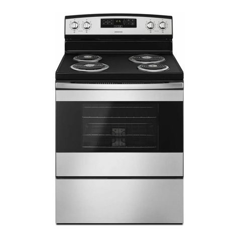
Amana AR03100 Series User manual

Gas Range
Owner's Manual
AR03100*
* Additionalalphanumericcharactersrepresentingother
models in series may follow each model number.
Please Read Manual Before Operating
Range
Installer
Leavethismanualandotherliteraturewithconsumerfor
futureuse.
Customer
Keeptheseinstructionsforfuturereference.Ifappliance
changesownership,besure this manual accompanies
range.
Pararecibirunmanualenespañolgratis,envíeporcorreo
o por fax su nombre, dirección, y número de modelo a:
AmanaAppliances
ConsumerCommunications/SpanishManual
2800220thTrail
PO Box 8901
Amana,Iowa52204-0001
USA
Númerodefax1-319-522-8158

2
Contents
Model Identification
Completeenclosedregistrationcardandpromptlyreturn.
If registration card is missing, call Consumer Affairs
Departmentat 1-800-843-0304 inside U.S.A.
319-622-5511outside U.S.A. When contacting Amana,
provideproduct information located on rating plate. Rating
plateislocatedontheovenframebehindbroilerdoor.
Recordthe following:
ModelNumber: ______________________________
ManufacturingNumber: ________________________
SerialorS/NNumber: _________________________
Dateof purchase:_____________________________
Dealer’sname and address: ____________________
__________________________________________
__________________________________________
Parts and Accessories
Purchasereplacementpartsandadditionalaccessories
(e.g.,refrigeratorshelves,dryerracks,orcooktop
modules)over the phone. Toorder accessories for your
Amanaproduct,call1-800-843-0304insideU.S.A.or
319-622-5511outsideU.S.A.
Service
Keepa copy of sales receipt for futurereference or in
case warranty service is required. Any questions or to
locatean authorized servicer, call1-800-NAT-LSVC
(1-800-628-5782)inside U.S.A.319-622-5511outside
U.S.A.Warranty service must be performed by an
authorizedservicer.Amana, also recommends contacting
anauthorized servicer if service is requiredafterwarranty
expires.
Asure™ Extended Service Plan
Amanaoffers long-term service protection for this new
range. Asure™ Extended Service Plan is specially
designedtosupplementAmana’sstrong warranty.
Thisplancoversparts,labor, and travel charges.
Call1-800-528-2682forinformation.
ImportantSafety Information.......................................3
ALL APPLIANCES.................................................. 4
OVEN ..................................................................... 4
SURFACECOOKINGUNITS .................................. 4
DelayedIgnition ...................................................... 4
VENTILATIONHOOD .............................................. 5
In Case ofFire ........................................................ 5
Precautions ............................................................ 5
Installation
Packing Material ..................................................... 5
Range Location ....................................................... 5
CabinetOpening ..................................................... 5
MinimumClearancestoCombustibleSurfaces ....... 6
SpecialCountertop Conditions ................................ 6
GasConnection Requirements................................ 6
Gas Supply Location............................................... 6
Gas SupplyPressure.............................................. 7
PressureRegulator Location ................................... 7
Convertingfor Use with NaturalGas
orPropane Gas....................................................... 7
Anti-tip BracketInstallation ..................................... 10
GasConnection ...................................................... 11
Testing for Gas Leaks ............................................. 11
SealOpenings ........................................................ 11
PlaceRange ........................................................... 11
Removaland Replacementof Range ....................... 12
Igniting and AdjustingTop Burner PilotFlame ......... 12
Test andAdjusting Surface BurnerFlame ............... 12
RemoveShipping Screws........................................ 13
Place Rangetopand Grates .................................... 13
IgniteOven Burner Pilot .......................................... 13
Test andAdjust Oven BurnerFlame ........................ 14
Operation
OperatingSurface Burners ...................................... 14
Cooking Utensils..................................................... 15
Prepare to Bake...................................................... 16
Baking .................................................................... 17
Adjusting FactorySet BakingTemperature ............. 17
Preparefor Broiling ................................................. 18
Broiling ................................................................... 18
BakingGuide .......................................................... 19
BroilingGuide ......................................................... 19
PoultryRoasting Guide ........................................... 20
Beef and Pork Roasting Guide ................................ 20
CareandCleaning
RemovingOvenDoor ............................................... 21
RemovingRangetopandGrates .............................. 21
Remove Grid,Pan, and Rack .................................. 21
RemovingOvenBottom........................................... 22
RemovingSurfaceBurners ...................................... 22
CleaningSurface Burners........................................ 23
Cleaning.................................................................. 24
BeforeCalling forService............................................26
Warranty ....................................................................27

3
IMPORTANT SAFETY INFORMATION
WARNING
!
To reduce the risk of the appliance tipping, it must
be secured by a properly installed anti-tip bracket.
To make sure bracket has been installed properly,
follow the procedure in the “Installing Anti-tip
Bracket” section for this manual. Bracket must be
engaged in the rear corner of the range.
• ALL RANGES CAN TIP
• INJURY TO PERSONS
COULD RESULT
• INSTALLANTI-TIP
BRACKET PACKED
WITH RANGE
• SEE INSTALLATION
INSTRUCTIONS
WARNING
!
To avoid death, personal injury orpropertydamage,
information in this manual must be followed exactly.
Donot store or use gasolineorother flammable vapors
and liquids in the vicinity of this or any other appliance.
WHAT TO DO IF YOU SMELL GAS
• Do not try to light any appliance.
• Do not touch any electrical switch; do not use any
phoneinyour building.
• Immediately call your gas supplier from a
neighbor’sphone. Follow the gas supplier’s
instructions.
• If you cannot reach your gas supplier, call the fire
department.
Installationand service must be performedbya qualified
installer, service agency or the gas supplier.
WARNING
!
To avoid personal injury, do not sit, stand or lean on oven
doororovendrawer.
WARNING
!
To avoid risk of electrical shock, personal injury, or death,
makesureyouroven has been properly grounded and
always disconnect it from main power supply before any
servicing.
CAUTION
!
Do not obstruct the flow of combustion or
ventilationair.
CAUTION
!
This appliance contains or produces a chemical or
chemicals which can cause death or serious illness and
which are known to the state of California to cause
cancer, birthdefectsor other reproductive harm. To
reduce the risk from substances in the fuel or from fuel
combustion make sure this appliance is installed,
operated, and maintained according to the instructions in
this booklet.

4
IMPORTANT SAFETY INFORMATION
SURFACE COOKING UNITS
1. UseProperPan Size—Select utensils having flat
bottomslarge enough to cover the surface burner
flame. The use of undersized utensils will expose a
portion of the burner flame to direct contact and may
resultinignition of clothing. Proper relationship of
utensiltoburnerwill also improve efficiency.
2. NeverLeave SurfaceBurnersUnattended—Boilover
causes smoking and greasy spillovers that may
ignite.
3. ProtectiveLiners—Donotuse aluminum foil to line
oven bottom except as suggested in the manual.
Improper installation of these liners may result in a
risk of electrical shock, or fire.
4. GlazedCooking Utensils—Onlycertain types of
glass, ceramic, earthware, or other glazed utensils
aresuitable for rangetop service without breakingdue
tosuddenchangeintemperature.
5. UtensilHandles Should be TurnedInwardandNot
ExtendOver Adjacent Surface Burners—Toreduce
the risk of burns, ignition of flammable materials, and
spillage due to unintentional contact with the utensil,
the handle of a utensil should be positioned so that it
isturnedinward,and does not extend over adjacent
surfaceunits.
6. Cleanrangetopwithcaution.To avoid steam burns,
do not use a wet sponge or cloth to wipe up spill on a
hotcookingarea.
7. Donotplace aluminum foil or food packaged in
aluminum foil directly on the flame.
Delayed Ignition
Surface Burners
Burnershould ignite within 4 seconds. If burnerdoes not
ignite within 4 seconds turn control knob to
OFF
position
andfollow directions in “Cleaning Surface Burners” and
“BeforeCalling for Service” section. Try burneragain.If
burner still does not ignite in 4 seconds, contact an
authorizedservicer.
Bake and Broil Burner Flame
Allownomorethan40–60secondsbeforeburnerignites
and heat is felt. To check for heat, open oven door to first
stopand place hand over oven door.If heat is not felt, turn
temperatureknobto
OFF
position.Ifburnerrepeatedly
failsto ignite, contact an authorized servicer.
ALL APPLIANCES
1. ProperInstallation—Be sure your appliance is
properlyinstalled and grounded by a qualified
technician.
2. NeverUse Appliance for Warming or Heating the
Room.
3. Do NotLeave Children Alone—Children should not be
aloneorunattendedintheareawheretheappliance
is in use. They should never be allowed to sit or stand
on any part of the appliance.
4. WearProtective Apparel—Loose fitting orhanging
garmentsshould never be worn while usingappliance.
5. UserServicing—Do not repair or replace any part of
theapplianceunless specifically recommended in the
manual.Allotherservicingshouldbereferredto a
qualifiedtechnician.
6. StorageinoronAppliance—Flammablematerials
shouldnot be stored in oven or nearsurface units.
7. DoNotUse Water on Grease Fires—Smother fire or
flame,or use dry chemical or foam-type extinguisher.
8. UseOnlyDry Potholders—Moist or damp potholders
on hot surfaces may result in burns from steam. Do
not let potholder touch burner. Do not use a towel or
other bulky cloth.
OVEN
1. UseCareWhenOpening Door—Let hot air or steam
escapebefore removingorreplacing food.
2. DoNot Heat UnopenedFoodContainers—Build-up of
pressure may cause container to burst and result in
injury.
3. ProtectiveLiners—Donotuse aluminum foil to line
ovenbottom.Improperinstallation of these liners can
causefire.
4. KeepOvenVentsDucts Unobstructed.
5. PlacementofOvenRacks—Alwaysplaceovenracks
in desired location while oven is cool.
6. Donottouchthe interior surfaces of the oven during
or immediately after use. Do not let clothing or other
flammablematerialcontactthe bake and broil burner.
7. Otherareasofthe oven can become hot enough to
causeburns,suchas vent openings, oven door, and
ovenracks.

5
VENTILATION HOOD
1. CleanVentilationHood Frequently—Grease should
not be allowed to accumulate on hood or filter.
2. Whenflamingfoods under hood, turn fan off. The fan,
if operating, may spread the flame.
In Case of Fire
Fires can occur as a result of over cooking or excessive
grease. Though a fire is unlikely, if one occurs, proceed
as follows:
Surface Burner Fire
1. Smotherthe fire with a nonflammable lid or baking
soda, or use a Class ABC or BC extinguisher. Not
water. Not salt. Not flour.
2. As soon as it is safe to do so, turn the surface
burnercontrols to
OFF
.
• As an added precaution, turn off gas supply.
Oven Fires
1. If you see smoke from oven, do not open oven door.
2. Turn oven control to
OFF
.
3. As an added precaution, turn off gas supply.
4. Turnonventto remove smoke.
5. Allow food or grease to burn itself out in oven.
6. If smoke and fire persist, call fire department.
7. If there is any damage to components, call repair
service before using range.
Precautions
• Do not cook food directly on rangetop surface, always
usecookware.
• Do not mix household cleaning products. Chemical
mixturesmay interact with objectionableor even
hazardousresults.
• Do not put plastic items on warm cooking areas. They
may stick and melt.
• Do not slide rough metal objects across rangetop
surface. Scratching or metal marking can result.
• Do not use damp sponge or dishcloth to clean rangetop
when range is hot. Steam from sponge or dishcloth can
burn.
• Do not leave fat heating unless you remain nearby. Fat
can ignite if overheated by spilling onto hot surfaces.
• Do not allow pots to boil dry as this can cause damage
to cooking surface and pan.
• Do not use rangetop surface as a cutting board.
Installation
Packing Material
Remove protective packing material from range. Tape
residue can be cleaned with a soft cloth and alcohol.
Range Location
Choose a location based on following factors.
• Draftscausedbyhome heating and air conditioning and
opendoorsorwindowscandisruptventilationair
pattern.Rangeshouldnotbeinstallednearwindows or
doors.
• Makesurethereis adequate space for proper
installation.
• Carefullyread all instructions before beginning
installation.
Cabinet Opening
WARNING
!
To avoid risk ofburns or fire by reachingover elements,
cabinetstorage space located above range should be
avoided.If cabinet storage is provided,installa range
hood that projects horizontally a minimum of 5 inches
beyond the cabinet bottom to reduce the risk.
Range should extend approximately 2 inches from
cabinet front to oven door handle. Use dimensions in
figurebelow and shown in “Special CountertopConditions”
sectiontopreparecabinetopening.
A
C
B
D
E
A—301/8to 30¼ inches
B—36 inches standard
C—35 inches standard
D—24 inches standard
E—25 inches standard
Standard Cabinet and Countertop Height

6
Special Countertop Conditions
Countertops such as ceramic tile tops cause cabinet and
countertoptobe higherthan 36inches.Followinstructions
belowwhen countertop is higher than 36inches.
1. Raiselevelinglegstomaximumlevel.
2. Measurefrom floorto side trim. If measurementis
less than height of countertop, floor must be
shimmed.
3. Shim floor using a piece of plywood same size as
rangeopening. Secureplywoodtofloor. Plywood
must be as secure as original flooring.
4. Install anti-tip bracket(s) and slide range into place.
Gas Connection Requirements
Before connecting this appliance to the gas supply piping
system, confirm installation meets the requirements of
local codes, or in the absence of local codes, with the
NationalFuel Gas Code, ANSI Z223.1-LatestEdition.
Theinstallationofappliances designed for manufactured
(mobile)home installation must conformwith
ManufacturedHomeConstructionandSafetyStandard,
Title 24 CFR, Part 3280, or when such standard is not
applicable,theStandardforManufacturedHome
Installation,ANSI225.1/NFPA 501A-Latest Edition, and
withlocal codes where applicable.
Gas Supply Location
Gas supply must be located in the area shown.
A
BCD
E
A—26 inches
B—20 inches
C—2¼ inches
D—4 inches
E—6 inches
Gas Supply Location
Minimum Clearances to Combustible
Surfaces
• Minimum clearance to rear wall is 0 inches.
• Minimum clearance to a vertical right or left side wall
extendingabovecooking surface is 3 inches.
• Minimumclearanceto countertop/cabinet on each side
is 0 inches.
• Minimumof30 inches between top of cooking surface
andbottomof an unprotected wood or metal cabinet.
• 24inchesbetweencookingsurfaceandprotectedwood
ormetalcabinetabove range. Cabinet bottom must be
protected by at least ¼ inch thick millboard with not
less than No. 28 MSG sheet steel, .015 inch thick
stainless steel, .024 inch thick aluminum, or .020 inch
thick copper.
A
B
C
D
EF
G
H
J
A—30 inches minimum
B— 0 inches
C—30 inches unprotected/24 inches protected minimum
D—13 inches
E—0 inches
F—25 inches maximum
G—36 inches maximum
H—3 inches minimum (Both sides of range)
J—18 inches minimum
Clearances to Combustible Surfaces

7
Converting for Use with Natural Gas or
Propane Gas
This range arrives from factory adjusted for use with
natural gas. If using LP/propane gas is desired, range
must be converted. See “Type 1” or “Type 2” regulator.
WARNING
!
To avoid electric shock that can cause personal injury or
death, disconnect main electrical supply to range before
servicing.
Converting Type 1 Pressure Regulator for Use with
LP/ Propane
1. Removepressure regulator cap with a wrench.
2. Removeplastic insert from pressure regulator cap.
• Plastic insert fits tightly in cap.
3. Reverseplastic insertand carefully push plastic
insert firmly into hole in pressure regulator cap.
• Capmustshow“LPG10”or“LP10”.
4. Placepressure regulator cap on pressure regulator
andtighten.
• Insertshouldnot disturb spring in body of regulator.
A
B
C
A—Cap
B—Plastic Insert (LP setting)
C—Spring Location
Type 1 Pressure Regulator
Gas Supply Pressure
CAUTION
!
To avoid property damage,maximum gas supply
pressure must not exceed 14" WCP.
• Applianceand individual shutoffvalvemust be
disconnected from the gas supply piping system during
any pressure testing of that system at test pressures in
excess of ½ psig (3.5kPa) (14" WCP).
• Appliance must be isolated from gas supply piping
systembyclosingmanualshutoffvalveduringany
pressure testing of the gas supply piping system at
test pressures equal to or less than ½ psig (3.5kPa)
(14"WCP).
• Gassupplypressure for checking regulator setting
must be at least 1" WCP above manifold pressure
shownonratinglabel.
Pressure Regulator Location
Remove rear cover to expose pressure regulator.
Regulator Cover

8
Converting Type 2 Pressure Regulator for Use with
LP/Propane
1. Removepressure regulator cap with a wrench.
2. Reversepressure regulator cap.
• Cap must show “LP”.
3. Placepressureregulator cap on pressure regulator
andtighten.
A
LP
A—Cap
Type 2 Pressure Regulator
Converting Surface Burners for Use with LP\Propane
1. Lifttherangetopoffoftherange.
• Apeg on each side of rangetop holds rangetop in
place.
RemoveRangetop
2. Turnall 4orifice hoods (tighten) counterclockwise
when facing front of range 1½ to 2 turns or until snug.
• Use½-inchwrench.
• Donotovertightenorificehoods.Iforificehoodsare
overtightened,gassupply can be cutoff or orifice
hoodthreads can strip.
A
B
Open Fully
A—Orifice Hood
B—Air Shutter
Orifice hood andAir Shutter
3. Pull all 4 air shutters fully open.
Converting Oven Burner for Use with LP\Propane
1. Openbroiler door and remove broiler rack, pan, and
grid.
2. Throughrectangular hole on rear of broilercavity,turn
orificehood(tighten),clockwisewhenfacingfrontof
range, 1½ to 2 turns or until snug.
• Donotovertightenorificehoods.Orificehoodscan
strip.
A
B
C
Open
Fully
A—Air Shutter Screw
B—Orifice Hood
C—Air Shutter
Converting Oven Burner
3. Openair shutterfully.

9
Converting Oven Thermostat for Use with
LP\Propane
1. Removeall (5) control knobs from range.
• Exposes 2 screws on burner control panel.
2. Remove2 screws from burner control panel.
• Paneldropsslightlyafterscrewsareremoved.
3. Graspbottomof burner control panel, gently lift and
pulloutpaneluntil clear of burner valve stems.
• Afterburner control panel clears valve stems,
continueto roll panel until free from range.Set
aside. See
Pivot Point
in illustration.
AB
C
D
A—Burner Control Knob
B—Pivot Point
C—Burner Control Panel
D—Screw
RemovingPanel
4. Turn the selector screw on oven thermostat so the
pointeris towards “LP”.
5. Reversesteps 1–3 to replace control paneland
knobs.
Selector Screw
LP N
OFF
LP N
OFF
LP N
OFF
Converting Oven Thermostat
Converting Type 1 Pressure Regulator for Use with
Natural Gas
1. Removepressure regulator cap with a wrench.
2. Removeplastic insert from pressure regulator cap.
• Plastic insert fits tightly in cap.
3. Reverse plastic insert and carefully push plastic insert
firmlyinto hole in pressure regulator cap.
• Insertmust show “NAT” orbeblank.
4. Placepressure regulator cap on pressure regulator
andtighten.
• Insertshouldnot disturb spring in body of regulator.
Converting Type 2 Pressure Regulator for Use with
Natural Gas
1. Removepressure regulator cap with a wrench.
2. Reversepressure regulator cap.
• Insert shows “NAT” or is blank.
3. Placepressure regulator cap on pressure regulator
andtighten.
Converting Surface Burners for Use with
Natural Gas
1. Lifttherangetopoffoftherange.
2. Turn all 4 orifice hoods (loosen) clockwisewhen
facing front of range 1½ to 2 turns.
• Use½-inch crescent wrench.
3. Close all 4 air shutters to approximately 1/8inch.

10
Converting Oven Burner for Use with Natural Gas
1. Removebroilerdrawer.
2. Turnorifice hood counterclockwise (loosen) 2 full
turns.
3. Close air shutter to approximately 3/8inch.
4. Replacebroiler door.
Converting Oven Thermostat for Use with Natural
Gas
1. Remove4 burner control knobsfromrange.
• Exposes 2 screws on burner control panel.
2. Remove2 screws from burner control panel.
• Paneldropsslightlyafterscrewsareremoved.
3. Graspbottomof burner control panel, gently lift and
pulloutpaneluntil clear of burner valve stems.
• Afterburnercontrol panel clears valve stems,
continueto roll panel until free from range.Set
aside.
4. Turn the selector screw so the pointer is towards “N”.
5. Reversesteps 1-3 to replace control paneland
knobs.
Anti-tip Bracket Installation
To reduce risk of rangetipping,secure range with a
properlyinstalledanti-tipbracket.
1. Measure 31/2inches from back wall on right and left
sideof cabinet cutout. Markmeasurements on floor
and draw a straight line connecting marks.
2. Position anti-tip bracket.
• Ifrange is installed beside cabinet(s), place anti-tip
bracketwith back edge on line drawn onfloor and
side of bracket against cabinet.
• If range is not installed beside cabinet(s), position
rangewhere it will beinstalled. Draw a linealong
sideofrangeonfloorfromfronttoback.Remove
range.Placeanti-tip bracket with back edge over
line drawn 31/2inches from back wall and side of
bracketover line drawn along side of range on floor.
• Anti-tip bracket can be installed on either right or
left side.
or
3 1/2"
Anti-tipBracket Location
3. Mark 2 hole locations in anti-tip bracket.
4. Drill 2 holes.
• If drilling into wood, use a 3/32 inch drill bit.
• If drilling into concrete, use a 3/16 inch masonry drill
bit and insert plastic anchors.
5. Secure bracket to floor using screws supplied.
6. Afterrange isslide into position, verify the range
levelingleg has engaged anti-tip bracket.
Verifying anti-tip bracket position
1. Afterrange isin place, open broiler door and remove
broiler rack, pan, and grid.
2. Removescrews infront of broiler area onside of
range that anti-tip bracket is installed.
3. Removepanelandlook towards back of oven and
check anti-tip bracket has engaged bracket.
4. Reinstall panel after checking anti-tip bracket.
Remove
Screws
Remove
Panel
VerifyAnti-tip Bracket Position

11
Gas Connection
Connect gas supply to regulator using hard pipe or
flexible connector (Check local codes). Pressure
regulator supplied with this appliance has a ½ inch NPT
femaleconnection.
• A manual shutoff, not supplied with range, must be
installed in an accessible location outside of range.
• Use joint compound that is resistant to action of
propanegason all male pipe threads.
• Usesuppliedpressureregulatoronly.
• Donotovertightengas fitting when attaching to
pressureregulator. Overtightening may crackregulator.
• Supportpressure regulator with wrench when installing
gas fitting.
WARNING
!
To avoid property damageor personal injury,only use a
new flexible connector that is AGA/CGA design certified.
• Do not use an old connector.
• Do not reuse a connector after moving appliance.
Gas Connection Examples
Testing for Gas Leaks
After final gas connection is made, turn on manual gas
valve and test all connections in gas supply piping and
range for gas leaks.
WARNING
!
To avoid property damage or seriouspersonalinjury,
never use a lighted match to test for gas leaks.
1. Place soap suds on connections.
• Bubbles appear if leak is present.
2. Ifbubbles appear, shut offgas supply valve.
3. Tighten joint if leak is at factory fitting.
• If leak is not at factory fitting, unscrew, apply more
joint compound, and tighten to correct leak.
4. Retestconnectionforleak after tightening.
• Retest any connections that were disturbed.
Test for Gas Leaks
Seal Openings
Openings in wall behind the range or on floor under range
must be sealed before sliding range into position.
Place Range
1. Sliderange into place.
• Leveling legs must be extended out ¼ inch to
engageanti-tip bracket.
2. Carefullylevelrangeusinglegsprovided.Rangemust
be level to cook and bake uniformly.
• Placea level on topoven rack or ontop of range
whenleveling.

12
Removal and Replacement of Range
1. Turn offgasvalveanddisconnect gas supply.
2. Removerange and placeaside.
3. Removeanti-tipbracketand reinstall anti-tip bracket
into new location using instructions in this manual.
4. Toreinstallrange,followinstructionsin“Installation”
section of this manual.
• Donotreuseaflexibleconnectoraftermoving
appliance.
Igniting and Adjusting Top Burner Pilot
Flame
1. Check that all burner control knobs are in the OFF
position.
2. Removegrates and lift off rangetop.
3. Ignite both top burner pilots with match.
• Pilot flame should be 1/4to 3/8inch high and
centered in the pilot housing.
Ignite Pilot
Surface Burner Pilot
4. If necessary, adjust pilot flame size. Remove
rangetopifnecessary.
• Tighten or loosenpilotadjustment screw,located
behindoventemperature knob, untilflame is 1/4to3/8
inch high and centered in pilot housing.
• If flame is too high, black marks (carbon) will form
onthe bottom of the rangetop.
Pilot Adjusment
Screw
PilotAdjustment Screw
Test and Adjusting Surface Burner Flame
Turn on burner.See“OperatingSurfaceBurners” section
forburner operating instructions. Surface burner should
ignitewithin4seconds. Properly adjusted surface burner
flames are clean and blue with a distinct inner cone
approximately ¼ inch to ½ inch long. Some yellow flame
isnormal when burning LP/Propane.
1/4 to 1/2 inch
Surface Burner Flame

13
Removerangetop to adjust air shutters. If burner flame is
blowing or noisy, reduce airflow to burner (close shutter).
If burner flame does not hold its shape, increase airflow to
burner(open shutter). Repeat testif necessary.
A
Open
Close
A—Air Shutter
AdjustAir Shutter
Remove Shipping Screws
Removeshipping screws.
Shipping Screws
Removing Surface Burners
Place Rangetop and Grates
Replacerangetopand place grates over burners. A peg
on each side of range holds rangetop in place.
Placing Rangetop and Grates
Ignite Oven Burner Pilot
1. Openbroilerdoorandremovebroilerpan,grid,and
rack.
2. In rear of broiler cavity, hold a match near pilot as
shownin illustration.
3. Quickly remove hand and match when pilot ignites.
Igniting Oven Burner Pilot

14
Operating Surface Burners
WARNING
!
To avoid risk ofserious personal injury, propertydamage,
orfire, do not leave burners unattended whilein
operation.Grease and spillovers canignite causing a fire.
CAUTION
!
To avoid risk of burns on standing pilot ranges, do not
touchareabetweenburner openings. Pilot flame under
rangetop can make rangetop hot to touch.
1. Push in and turn control knob counterclockwise until
theburnerignites.
• Burner should ignite within 4 seconds.
OFF
Surface Burner Control Knob
2. After gas ignites, turn control to desired setting.
• Each control knob can be set to any required
cookingtemperature.Burnersettingsdonothave
distinct clicks.
• Use
HI
tobring food to boilingtemperatures. When
foodisboilingtemperature setting should be
reduced.
• Afterlighting burner do not operate burner for long
periodsoftime without cookware on the grate. The
finish on the grate can chip without cookware to
absorbheat.
3. Turncontrolknobto
OFF
positionwhenfinished
cooking.
Delayed Surface Burner Ignition
Burnershould ignite within 4 seconds. If burnerdoes not
ignite within 4 seconds turn control knob to
OFF
position
andfollow directions in “Cleaning Surface Burners” and
“BeforeCalling for Service” section. Try burneragain.If
burner still does not ignite in 4 seconds, contact an
authorizedservicer.
Operation
Test and Adjust Oven Burner Flame
Turn onovenburner.See “Baking” section forovenburner
operatinginstructions. Properly adjusted oven burner
flames are blue with a distinct deep blue inner cone
approximately ½ inch long. When using natural gas,
flameshould not have any yellow flame when burning.
SomeyellowflamewhenburningLP\propanegasis
normal.
Flameshouldnotbe visible in the oven cavity when
burningandshouldnot extend into the oven cavity beyond
theremovableovenbottom.
• Ifburnerflameis blowing or noisy, reduceairflowto
burner.
• If burner flame is yellow and does not hold its shape,
increaseairflow to burner.
1. Check that oven temperature knob is in OFF position.
2. Openbroilerdoorandremovebroilerpan,grid,and
rack.
3. Throughrectangularholeinrearofbroilercavity,
loosen air shutter lock screw and open or close air
shutter.
• Tightenair shutter lock screw after adjusting.
A
B
Open Close
A—Air Shutter Lock Screw
B—Air Shutter
Adjust Oven BurnerAir Shutter
4. Repeat test if necessary.
5. Replace broiler pan, grid, and rack.

15
Adjusting Burner Flame Size
• Whileturningthe burner control knob, watch the burner
flame.
• Flame size should match the size of the pan. Do not
allow the flame to extend up the sides of the pan.
Flames that extend up the sides of the pan can ignite
clothing, make handle hot, or burn.
Adjusting Burner Flame Size
Cooking Utensils
• Use proper pan size. Do not use a pan that has a
smaller bottom than surface burner. Do not use utensils
thatoverhanggrate by more than 1 inch.
More than 1 inch
overhang
Does not cover burner
Use Proper Pan Size
• Use care when using glazed cooking utensils. Some
glass,earthenware,orother glazed utensils break due
tosudden temperature changes.
• Select utensils without broken or loose handles.
• Handlesshould not be heavy enough to tiltpan.
• Do not use stove top grills on your range. Stove top
grills cause incomplete combustion and can create
levelsof carbon monoxideaboveallowable standards.
• Do not use a wok with a ring stand. Use flat bottom
wok.
Flat Bottom Wok

16
To avoid pan wobbling,use a pan with a flat bottom.
Determine if pan has a flat bottom.
1. Rotate a ruler along bottom of pan. If pan is not flat,
gaps between bottom of pan and edge of ruler occur.
2. A small groove or mark on a pan does not effect
cooking times. However, if a pan has a gap, formed
rings, or an uneven bottom, it does not cook
efficiently and in some cases may not boil liquid.
Flat Bottom Pan
Utensil Material Characteristic
Type Temperature
Response Uses
Aluminum Heats and
cools quickly Frying, braising,
roasting
Cast Iron Heats and
cools slowly Low heat
cooking, frying
Copper Tin
Lined Heats and
cools quickly Gourmet
cooking, wine
sauces, egg
dishes
Enamelware Depends on
base metal Low heat
cooking
Ceramic (Glass) Heats and
cools slowly Low heat
cooking
Stainless Steel Heats and
cools at
moderate rate
Soups, sauces,
vegetables,
general cooking
Prepare to Bake
Remove Items Stored in Oven
Remove any pans and other cooking utensils stored in
oven. Items left in oven can cause damage to the oven or
itemin oven.
Never store the broiler pan or place utensils directly on
the oven bottom. If the broiler pan or utensils are left on
the oven bottom while heating, the oven bottom can chip
orbedamaged.
Remove Items Stored in Oven

17
Baking
1. To preheat oven, turn oven temperature knob to
desiredtemperature.
• Preheatovenforapproximately 15-20 minutes.
2. Placefoodinoven.
3. Aftercooking time elapses, remove food andturn
oventemperatureknobto
OFF
.
TemperatureKnob
Check for Bake Burner Flame
Allownomorethan40–60secondsbeforeburnerignites
and heat is felt. To check for heat, open oven door to first
stopand place hand over oven door.If heat is not felt, turn
surfaceburnercontrolknob to OFF position. If burner
repeatedlyfails to ignite, contact an authorized servicer.
Adjusting Factory Set Baking Temperature
Oven temperature is set at factory. When first using oven,
follow recipe times and temperatures. If you think oven is
too hot or too cool, temperature can be adjusted. Before
adjusting oven baking temperature, test a recipe by using
atemperature set higher or lower than therecommended
temperature. The baking results should help you to
decide how much adjustment is needed.
1. Pull oven thermostat knob straight out from control
panel.
2. Turnknob over and loosen screws usingPhillips
screwdriver.
•Do not remove screws.
3. While holding knob front, turn outer part of knob until
pointer points to next line.
• Turnouterknob clockwise to decrease or counter-
clockwisetoincrease temperature.
• Eachlineadjuststemperature approximately 10
degreesFahrenheit.
• Only move knob one line at a time.
Oven Rack Placement
Positionovenrackbefore turning oven on.
WARNING
!
To avoid damaging oven linerorcreating fire, do not line
ovenbottom or oven racks withfoil.
1. Pull rack forward to stop position.
2. Raise front edge of rack and pull until rack is out of
oven.
3. Place rack in desired rack position.
• Curvededgeofrack must be toward rear of oven.
Oven Rack Placement
Pan Placement
• Keep pans and baking sheets 2 inches from oven
walls.
• Stagger pans placed on different racks so one is not
directlyoverthe other.
PanPlacement

18
4. Tighten screws with pointer in new position and
replaceknob on control panel.
• Useoven with knownrecipebefore moving pointer
again.
D
E
C
R
E
A
S
E
I
N
C
R
E
A
S
E
Loosen screws
Pointer
Prepare for Broiling
WARNING
!
To avoid risk of fire, do not line the broiler grid with foil.
• Foil may trap grease on top of grid close to burner
causing a fire.
• Neverleave ovenunattendedwhile broiling.
Overcookingmay result in afire.
Broiling Tips
• Removeexcess fat from meat before broiling. Cut
edgesof meat to prevent curling.
• Place food on a cold ungreased broiling pan. If pan is
hot, food sticks.
• All food except fish should be turned at least one time.
Begin broiling with skin side down.
• Season meat after it has browned.
• Broilingdoesnotrequirepreheating.
• Begin cooking using suggested rack levels in
Broiling
Guide
section to test broiler results. If food is not brown
enough, cook on a higher rack position. If food is too
brown, cook on a lower rack position.
Broiling
1. Openbroiler door, slideout broiler rack, center food
onbroiling grid, and slide broiler rack into oven.
2. Closebroiler door.
3. Turnoventemperatureknobto
BROIL
.
4. After broiling, open broiler door, slide out broiler rack,
removefood from broiling grid, slidebroilerrack into
oven,andclosebroiler door.
5. Turn oven temperature knob to
OFF
.
A
B
C
A—Broiler Grid
B—Broiler Pan
C—BroilerRack
Broiler Pan and Grid
Check Broiler Flame
Allownomorethan40–60secondsbeforeburnerignites
and flame is seen. If burner does not ignite turn
temperatureknobto
OFF
position.Ifburnerrepeatedly
fails to ignite within 40–60 seconds contact an authorized
servicer.

19
Baking Guide
Follow these recommendations only as a guide for times and temperatures. Times, rack position, and temperatures
may vary depending on conditions and food type. For best results, always check food at minimum time.
Food Oven Temperature
(°Fahrenheit) Cooking Time
(Minutes)
Angel Food Cake 350 28–50
Biscuits 350–375 8–16
Muffins 375–400 17–23
Cookies 325–350 7–18
Cupcakes 325–375 15–20
Brownies 325–350 25–35
Layer Cakes 325–350 25–35
Pound Cake 325 40–60
Fresh Pies 375–425 35–50
Nut Bread 350 45–55
Broiling Guide
Follow these recommendations only as a guide for times and temperatures. Times, rack position, and temperatures
may vary depending on conditions and food type. For best results close broiler door and always check food at
minimum time.
Food Thickness
(Doneness) Rack position
(1=Highest 3=Lowest) Cooking time
(Minutes)
Beef Steak 1" (med.) 2 14–16
Beef Steak 1" (well) 2 23
Beef Steak 1½" (med.) 2 23–28
Beef Steak 1½" (well) 2 33
Beef ground (¾"–1") 2 12–17
Fish Fillets and Steaks 3 15–20
Pork Chops or Steak 1" 3 15–16
Pork Chops or Steak 1½" 3 23–28
Bacon 3 12–17
Ham Slice (pre-cooked) ½" 3 12–17
Ham Slice (pre-cooked) 1" 3 20–25

20
Poultry Roasting Guide
Follow these recommendations only as a guide for times and temperatures. Times, rack position, and temperatures
may vary depending on conditions and food type. For best results, always check food at minimum time.
Food Oven temperature
(°Fahrenheit) Cooking time
(Hours)
Whole Chicken (4 lbs to 5 lbs) 375 1½–1¾
Whole Chicken (Over 5 lbs) 375 1¾–2
Turkey (6 lbs to 8 lbs) 325 3–3½
Turkey (8 lbs to 12 lbs) 325 3½–4
Turkey (12 lbs to 16 lbs) 325 5
Turkey (16 lbs to 20 lbs) 325 5–6
Turkey (20 lbs to 22 lbs) 325 6–7½
Duck (3 lbs to 5 lbs) 325 1½–2
Beef and Pork Roasting Guide
Follow these recommendations only as a guide for times and temperatures. Times, rack position, and temperatures
may vary depending on conditions and food type. For best results, always check food at minimum time.
Food Oven Temperature
(°Fahrenheit) Cooking time
(Minutes per pound)
Beef Roast (Rare) 325 25–30
Beef Roast (Medium) 325 31–35
Beef Roast (Well) 325 38–40
Rolled Roast (Rare) 325 37–41
Rolled Roast (Medium) 325 41–45
Rolled Roast (Well) 325 48–50
Fresh Whole Ham 325 27–33
Pork Loin 325 35–40
Pork Shoulder, Butt 325 35–40
Pork Picnic Shoulder 325 30–35
Mild Cured Ham Picnic, Shoulder 350 20–30
Table of contents
Other Amana Range manuals

Amana
Amana AGR5735QDB User manual

Amana
Amana ACR2303MFW User manual

Amana
Amana AER5823XAB1 User manual

Amana
Amana ZRT6510 User manual

Amana
Amana AGG200AAW0 User manual

Amana
Amana AES5730BA User instructions

Amana
Amana 8113P732-60 User manual

Amana
Amana AER5845RAB User instructions

Amana
Amana AGR4230BAW User manual

Amana
Amana AGR3530AAW User manual

Amana
Amana AGS5730BDW User manual

Amana
Amana EvenAir ZRRC8000 User manual

Amana
Amana AER5722BAS User manual

Amana
Amana W10531343B User manual

Amana
Amana AER5630BAS User manual

Amana
Amana AES1350BAW User manual

Amana
Amana Easy Touch Control 800 User manual

Amana
Amana AGR6011VDW3 User manual

Amana
Amana AGS3760BD Parts list manual

Amana
Amana BigOven ACF7225A User manual