ROOMSET
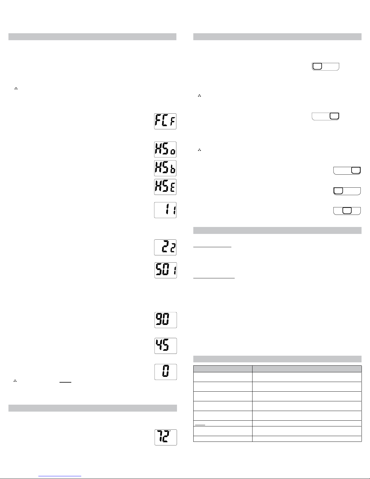
8. Room temperature offset(+9°Fto-9°F)(+4.5°Cto-4.5°C)
Adjusttocalibratedisplayedroomtemperaturetomatchactualroom
temperature.
Note:When not set to 0, ROOM will display.
Pressthedownorupbuttontoselect.
SlideMode switchtoHeatorCooltoexitcongurationmode..
SET
7. Minimum Cool Setpoint(45°Fto90°F)(7.0°Cto32.0°C)
AdjusttocontroltheminimumCoolsettemperatureallowed.
Pressthedownorupbuttontoselect.
PresstheRIGHT buttontoadvancetothenextscreen.
SET
6. Maximum Heat Setpoint(45°Fto90°F)(7.0°Cto32.0°C)
AdjusttocontrolthemaximumHeatsettemperatureallowed.
Pressthedownorupbuttontoselect.
PresstheRIGHT buttontoadvancetothenextscreen.
5. Staged Off Outputs(showsonlyforHP)
Selectwhethertheoutputsforheatingandcoolingarestagedoff
independentlyoraresatisedsimultaneously.
1= EconomyMode–Outputsarestagedonandoffinaccordancewithset
pointanddifferential.
0= ComfortMode–Outputsarestagedonandandallstagescycleoff
simultaneouslywhensetpointissatised.
Pressthedownorupbuttontoselect.
PresstheRIGHT buttontoadvancetothenextscreen.
ROOM
CAUTION!
:
Donotuseairconditioningwhentheoutdoortemperatureisbelow50
degrees.Thiscandamageyourairconditioningsystemandcausepersonal
injuries.
1. MovetheHigh/Auto/LowswitchtotheAutoposition.
2. MovetheCool/Off/Heat switchtoHeatorCool,dependingontheseason.
Starting the Thermostat
3. Temperature Differential – Stage 1 – (1°F to 5°F) (0.5°C to 2.5°C)
Setthenumberofdegreesbetweenyour“setpoint”temperatureandyour“turn
on”temperatureforrststage.
Pressthedownorupbuttontosetdifferentialvalue.
PresstheRIGHT buttontoadvancetothenextscreen.
DIFF
Conguration Mode Settings
ThesetupscreensforCongurationModeareasfollows:
1. Temperature Scale (F or C) –ChooseFahrenheitorCelsius.
Pressthedownorupbuttontoselect.
PresstheRIGHT buttontoadvancetothenextscreen.
DIFF
4. Temperature Differential – Stage 2 – (1°F to 5°F) (0.5°C to 2.5°C)(showsonlyforHP)
Setthenumberofdegreesbetweenwhenstage1turnsonandstage2turnson.
Pressthedownorupbuttontosetdifferentialvalue.
PresstheRIGHT buttontoadvancetothenextscreen.
Configuration Mode
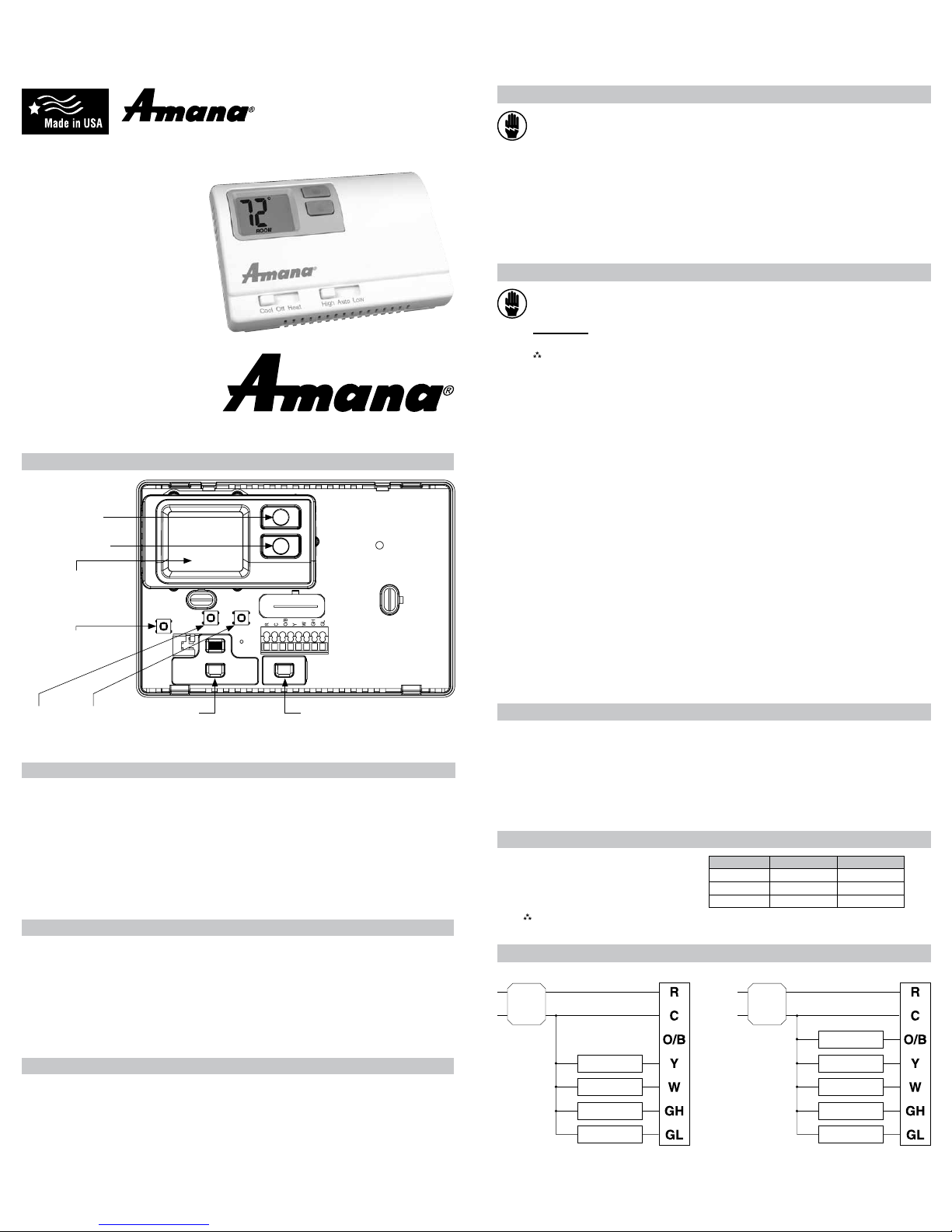
ThecongurationmodeisusedtosettheAmana® 2246003tomatchyourheating/coolingsystem.
ToconguretheAmana® 2246003,performthefollowingsteps:
1. SlidetheModeswitchtotheOFFposition.
2. Removethecoverofthethermostatbygentlypullingononeofthecorners.
3. SimultaneouslyholdtheLEFT &RIGHT buttonsinfor2secondswhiletheAmana® 2246003isin
OFFmode.
4. Pressthedownorupbuttontochangesettingswithineachscreen.
5. PresstheRIGHT buttontoadvancetothenextscreen.
Note:The LEFT button will return you to the previous screen.
6. Toexitcongurationmode,slidetheModeswitchtoHeatorCool.
2. Heating System
HSo – Heatpump,coolactivereversingvalve
HSb – Heatpump,heatactivereversingvalve
HSE – Electricheatsystem
Oncethethermostatisinstalled,itshouldbethoroughlytested.
CAUTION!:
Do not energize the air conditioning system when the outdoor temperature is
below 50 degrees. It can result in equipment damage or personal injury.
Testing the Thermostat
Mode of Operation
TheAmana® 2246003isathermostatfor24VACsystems.
Heat Pump Operation
Thethermostatactivatestheheatpumpwhentheroomtemperatureisbelowtheheatset
temperature(bythedifferentialtemperature).Auxiliaryheatwillbeactivatediftheroomtemperature
continuestodrop.Theheatoutputsarestagedoff(congurable,setting5)astheroomtemperature
increases.Thethermostatwillnotletthecompressorcomeonforfourminutesafteritturnsoff.This
protectsyourcompressor.
Electric Heat Operation
Thethermostatactivatedtheelectricheatwhentheroomtemperatureisbelowtheheatset
temperature(bythedifferentialtemperature).Theheatisturnedoffwhentheroomtemperatureraises
toonedegreeabovetheheatsetpointtemperature.
Whentheroomtemperatureisgreaterthanthecoolsettemperature(bythedifferentialtemperature),
thecoolingdeviceisactivated.Thethermostatwillnotletthecompressorcomeonforfourminutes
afteritturnsoff.Thisprotectsyourcompressor.
TheAmana® 2246003hasthefollowingoperatingmodes:
Cool
,
Off
,
Heat
.InOFFmode,the
thermostatwillnotturnonheatingorcoolingdevices.IntheHeatmode,thethermostatcontrolsthe
heatingsystem.IntheCoolmode,thethermostatcontrolsthecoolingsystem.Theindoorfancanbe
turnedoninalloperatingmodesusingtheFanswitch.
• Set fan to HIGH:forcontinuoushighspeedoperation
• Set fan to LOW:forcontinuouslowspeedoperation
• Set fan to AUTO:forlowspeedfanoperationonlyduringaheatorcoolcycle
Troubleshooting
Symptom Remedy
Nodisplay Checkfor24VACatthermostat;displayisblankwhen24VACisnot
present
Systemfandoesnotcomeon
properly
Verifywiringiscorrect
Thermostatturnsonandofftoo
frequently
Adjusttemperaturedifferential(see“TemperatureDifferential,”Stage1,
Step3)
Fanrunscontinuously CheckfanLow/Auto/HIghswitch.LoworHighpositionrunsindoorfan
continuously
Roomtemperatureisnotcorrect Verifywallholeispluggedwithputtyorinsulation;calibratethermostat
(see“Conguration,”Step8)
ROOMdisplays Roomtemperatureoffsetisnotzero(see“Conguration,”Step8)
Auxiliaryheatnotonsoonenough Adjustdifferentialfor2ndstageheatingifrequired(seeConguration,
Steps3&4)
Problemnotlistedabove PresstheResetbuttononce;displaywillberefreshed
CoolOffHeat
Cool Test
1. SlideModeswitchtoCoolmode.
2. Adjustsettemperaturesoitis5degreesbelowroomtemperature.
3. Airconditioningshouldcomeonwithinafewseconds.
4. Adjustthesettemperature2degreesabovetheroomtemperatureandtheA/Cshouldturnoff.
Theremaybeafandelayonyoursystem.
Note:There is a four minute time delay to protect the compressor after it turns off. To
temporarily bypass the four minute delay, slide the Mode switch to OFF for 2 seconds
and then back to Cool.
CoolOffHeat
Heat Test
1. SlideModeswitchtoHeatmode.
2. Adjustthesettemperaturesoitis5degreesabovetheroom
temperature.
3. Heatshouldcomeonwithinafewseconds.
4. Adjustthesettemperaturesoitis2degreesbelowtheroom
temperatureandtheheatshouldturnoff.Theremaybeafandelayonyoursystem.
Note:For Heat pumps, there is a four minute time delay to protect the compressor after it turns
off. To temporarily bypass the four minute delay, slide the Mode switch to OFF for 2
seconds and then back to Heat.
LowAutoHighLowAutoHigh
LowAutoHigh
LowAutoHighLowAutoHigh
Fan Test
1. SlideFanswitchtoHighposition.
2. Indoorfanturnsoninhighspeed.
3. SlideFanswitchtoLowposition.
4. Indoorfanturnsoninlowspeed.
5. SlideFanswitchtoAutoposition.
6. Indoorfanturnsoff.
LIAF173