Input:
• Voltage:18-30VAC
Output:
• Maximum:1ampperterminal(3amptotalforallterminals)
• Temperature control ranges: 45°Fto90°F(7°Cto32°C)Accuracy:±1°F(±0.5°C)
• Differential range: 1°Fto3°F(0.5°Cto1.5°C)
• System congurations:
Single-stageheat,single-stagecoolorsingle-stageheat
pump,gas,oil,electric
• Terminations:R,W,Y,O,B,G,C
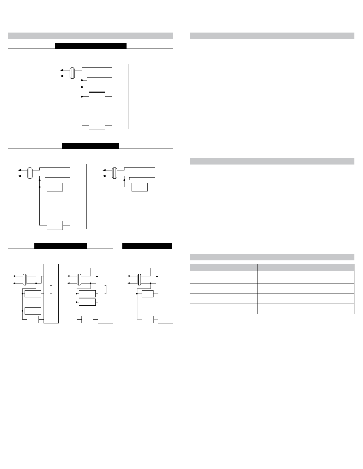
Parts Diagrams
• Controls Single Stage Heating/
Cooling Systems
• Single Stage Heat Pump Systems
• Compatible with Gas, Oil or
Electric Systems
• Millivolt and Hydronic (water or
steam) System Compatible
• Mercury-Free, Environmentally
Safe
ResetSwitch
Electric/Gas
Jumper
Mode
Switch
Fan
Switch
Freeze
Switch
HighTemp.
Switch
NonHP–HP
Jumper
RCWYBOG
GAS
ELEC
SET
ROOM
LO BAT
DIFF
Lowbatterysignal
Temperature
differentialsetting
Roomtemperature
Roomtemperature
setpoint
Specifications
Important Safety Information
• Alwaysturnoffthethermostatbeforeinstalling,removing,cleaning,orservicing;turnoffthepoweratthemain
powersourcebyunscrewingfuseorswitchingoffcircuitbreaker
• Donotswitchto“Cool”ifroomtemperatureisbelow50°F(10°C);thiscoulddamageyourA/Csystemandcause
injury
• Donotinstallonvoltageshigherthan30VAC
• Allwiringmustconformtolocalandnationalbuildingandelectricalcodesandordinances
• Whilecleaning,donotgetsoapdirectlyonthermostatswitchesorLCDreadout;onlyuseadampclothwithamild
soaptowipeoutsideofthermostatcover
Package Contents/Tools Required
Package includes:Amana® 2246002non-programmablethermostatonbase,thermostatcover,wiringlabels,
screwsandwallanchors,batteries(ifapplicable),Installation,OperationandApplicationGuide.
Tools required for installation:Drillwith3/16”bit,hammer,screwdriver.
Installation, Operation &
Application Guide
www.amana-ptac.com
2246002
General Description
• TheAmana® 2246002thermostatisadigital, mercury-free, non-programmable, electronic thermostat
• Compatiblewithsingle-stageheating systems, heating/cooling systems,andheat pump systems;workswith
gas, oil, or electricsystems
• Compatibleasamaster thermostatinzonedsystemapplications
• Freeze Protection Feature:Protectspipesfromfreezing!Iftheroomtemperaturedropsto40°F,thethermostat
automaticallyturnsontheheat;thethermostatmustbeintheHeatposition;worksevenifthebatteriesaredead
• Built-in Compressor Protection for Air Conditioners:ToprotecttheA/C’scompressor,thereisa5-minute
delaybetweenthesystemturningoffandtheA/Cstarting
• System Customization:ChooseFahrenheitorCelsiusdisplay;threeavailabletemperature differential
settings
To Remove Existing Thermostat
ELECTRICAL SHOCK HAZARD
– Turn off power at the main service panel by removing the fuse
or switching the appropriate circuit breaker to the OFF position before removing the existing
thermostat.
1. Turnoffpowertotheheatingandcoolingsystembyremovingthefuseorswitchingofftheappropriatecircuit
breaker.
2. Removecoverofoldthermostat.Thisshouldexposethewires.
3. Labeltheexistingwireswiththeenclosedwirelabelsbeforeremovingwires.
4. Afterlabelingwires,removewiresfromwireterminals.
5. Removeexistingthermostatbasefromwall.
6. Refertothefollowingsectionforinstructionsonhowtoinstallthisthermostat.
To Install Thermostat
ELECTRICAL SHOCK HAZARD
– Turn off power at the main service panel by removing the fuse
or switching the appropriate circuit breaker to the OFF position before removing the existing
thermostat.
IMPORTANT:Thermostat installation must conform to local and national building and electrical codes and
ordinances.
Note:
Mountthethermostataboutvefeetabovetheoor.Donotmountthethermostatonanoutside
wall,indirectsunlight,behindadoor,orinanareaaffectedbyaventorduct.
1. Turnoffpowertotheheatingandcoolingsystembyremovingthefuseorswitchingofftheappropriatecircuit
breaker.MovetheCool/OFF/HeatswitchtoOFF
.
2. MovetheFAN AUTO/ONswitchtoAUTO.
3. Toremovecover,insertandtwistacoinorscrewdriverintheslotsonthetopofthethermostat.
4. Putthermostatbaseagainstthewallwhereyouplantomountit(Besurewireswillfeedthroughthewireopening
inthebaseofthethermostat).
5. Marktheplacementofthemountingholes.
6. Setthermostatbaseandcoverawayfromworkingarea.
7. Usinga3/16”drillbit,drillholesintheplacesyouhavemarkedformounting.
8. Useahammertotapsuppliedanchorsintomountingholes.
9. Alignthermostatbasewithmountingholesandfeedthecontrolwiresthroughwireopening.
10. Usesuppliedscrewstomountthermostatbasetowall.
CAUTION!
:
Besureexposedportionofwiresdoesnottouchotherwires.
11. Tightenscrewsonterminalblock.Gentlytugwiretobesureofproperconnection.Doublecheckthateachwire
isconnectedtotheproperterminal.
12. Setthefan jumpertoelectricorgas/oil,andheatpumpjumpertoNON-HPorHP.
13. Replacecoveronthermostatbysnappingitinplace.
14. Turnonpowertothesystematthemainservicepanel.
Replacing Wiring Labels
Replacetheoldlabelswiththeenclosednewlabels:
Old New Type
F,G G Fancontrolrelay
O O Coolactivereversingvalve
B B Heatactivereversingvalve
Y,Y6 Y Coolingcontrol
H,W,4 W
Heatingcontrol
C Transformer,commonside
M,4,RH,RS,R R Transformer,hotside
C YorC
IftheCterminalisthecoolingcontrol,connecttoYterminal;ifitisthe
commonsideofthetransformer,connecttoCterminal
Non-Programmable Electronic Thermostat