Amano American Sanders Super 7R 240V User manual
Edger
Super 7R 240V
Operator’s Manual

Contents
Operator Safety Instructions...............................................4
General Power Tool Safety Warnings.................................5
Safety Warnings for Sanding Operations...........................6
Kickback and Related Warnings.......................................7
Additional Rules for Safe Operation...................................7
Machine Components.........................................................8
Machine Specifications.......................................................9
Safety Instructions..............................................................9
Dust Collection..................................................................10
Machine Setup.................................................................11
Operating Instructions.......................................................11
Adjustment Procedures....................................................12
Sanding Cuts & Sandpaper..............................................12
Routine Maintenance.......................................................12
Maintenance................................................................13
Carbon Brushes................................................................13
Gearbox Lubricant..........................................................13
Parts Manual & Notes......................................................14
Electrical Schematic.........................................................15
Lower Assembly...............................................................16
Upper Assembly................................................................18
Limited Warranty...............................................................23
READ THIS BOOK
This book has important information for the use and safe operation of this machine. Failure to read this book prior to
operating or attempting any service or maintenance procedure to your American Sanders machine could result in injury
to you or to other personnel; damage to the machine or to other property could occur as well. You must have training in
the operation of this machine before using it. If your operator(s) cannot read this manual, have it explained fully before
attempting to operate this machine.
All directions given in this book are as seen from the operator’s position at the rear of the machine.
***This product is intended for commercial use only***
WARNING!
The Products sold with this Manual contain or may contain chemicals that are known to certain governments (such as the State of
California, as identied in its Proposition 65 Regulatory Warning Law) to cause cancer, birth defects or other reproductive harm. In
certain locations (including the State of California) purchasers of these Products that place them in service at an employment job site
or a publicly accessible space are required by regulation to make certain notices, warnings or disclosures regarding the chemicals that
are or may be contained in the Products at or about such work sites. It is the purchaser’s responsibility to know the content of, and
to comply with, any laws and regulations relating to the use of these Products in such environments. The Manufacturer disclaims any
responsibility to advise purchasers of any specic requirements that may be applicable to the use of the Products in such environments.
3

4
Operator Safety Instructions
DANGER: Failure to read the Owner’s Manual prior to operating or servicing your American Sanders machine
could result in injury to you or to other personnel; damage to the machine or to other property could
occur as well. You must have training in the operation of this machine before using it. If you or your
operator(s) cannot read English, have this manual explained fully before attempting to operate this
machine.
DANGER: A. Sanding/nishing wood oors can create an explosive or combustible environment. Do not operate
this machine around solvents, thinners, alcohol, fuels, oor nishes, wood dust or any other ammable
materials. Cigarette lighters, pilot lights, electrical sparks and all other sources of ignition should be
extinguished or avoided. Keep work area well ventilated.
B. Dust generated from sanding wood oors can spontaneously ignite or explode. Promptly dispose
of any sanding dust in a metal container clear of any combustibles. Do not dispose in a re.
DANGER: A. Electrocution could occur if the machine is being serviced while the machine is connected to a
power source. Disconnect the power supply before servicing.
B. Electrocution or re could occur if the machine is being operated with a damaged power cord.
Keep the power cord clear of the pad. Always lift the cord over the machine. Do not move the
machine by the power cord.
C. Shock hazard. Do not use the machine if it has been rained on or sprayed with water.
DANGER: To avoid injury keep hands, feet, and loose clothing away from all moving parts on the machine.
Disconnect the power cord before replacing the pad, changing the abrasive, or when servicing. Do
not operate the machine unless all guards are in place. Never leave the machine unattended while
connected to a power source.
WARNING: Injury can occur if protective clothing or equipment is not used while sanding. Always wear safety
goggles, protective clothing, and dust mask while sanding.
WARNING: This sander is not to be used on pressure treated wood. Some pressure treated woods contain
arsenic and sanding pressure treated wood produces hazardous dust. Inhaling hazardous dust from
pressure treated wood can cause serious injury or death. Sanding pressure treated wood decks or
uneven surfaces can damage the sander which is not covered under warranty or damage waiver.
WARNING: Any alterations or modications of this machine could result in damage to the machine or injury to the
operator or other bystanders. Alterations or modications not authorized by the manufacturer voids
any and all warranties and liabilities.
WARNING: Risk of explosion. Floor sanding can result in an explosive mixture of ne dust and air. Use oor
sanding machine only in a well-ventilated area free from any ame or match.
In this Operation Manual you will find three statements that you must read and observe to ensure safe operation of this
machine.
DANGER means: Severe bodily injury or death can occur to you or other personnel if the DANGER
statements found on this machine or in this Operation Manual are ignored or are not adhered to. Read
and observe all DANGER statements found in this Operation Manual and on your machine.
WARNING means: Injury can occur to you or to other personnel if the WARNING statements found on
your machine or in the Operation Manual are ignored or are not adhered to. Read and observe all
WARNING statements found in this Operation Manual and on your machine.
CAUTION means: Damage can occur to the machine or to other property if the CAUTION statements found
on your machine or in this Operation Manual are ignored or are not adhered to. Read and observe all
CAUTION statements found in this Operation Manual and on your machine.

5
General Power Tool Safety Warnings
WARNING: Read all safety warnings and
instructions. Failure to follow warnings and
instructions may result in electric shock, re and
or serious injury.
Save all warnings and instructions for future use.
The term “power tool” in the warnings refers to
your main-operated (corded) power tool or battery
operated (cordless) power tool.
1) Work area safety
a) Keep work area clean and well lit. Clutter or dark
areas invite accidents.
b) Do not operate power tools in explosive
atmospheres, such as in the presence of
ammable liquids, gases, or dust. Power tools
create sparks which may ignite the dust or fumes.
c) Keep children and bystanders away while
operating a power tool. Distractions can cause
you to lose control.
2) Electrical safety
a) Power tool plugs must match the outlet. Never modify the
plug in any way. Do not use any adapter plugs with earthed
(grounded) power tools. Unmodied plugs and matching
outlets will reduce risk of electric shock.
b) Avoid body contact with earthed or grounded surfaces such
as pipes, radiators, ranges, and refrigerators. There is an
increased risk of electric shock if your body is earthed or
grounded.
c) Do not expose power tools to rain or wet conditions. Water
entering a power tool will increase the risk of electric shock.
d) Do not abuse the cord. Never use the cord for carrying,
pulling or unplugging the power tool. Keep cord away
from heat, oil, sharp edges or moving parts. Damaged or
entangled cords increase the risk of electric shock.
e) When operating a power tool outdoors, use an extension
cord suitable for outdoor use. Use of cord suitable for
outdoor use reduces the risk of electric shock.
f) If operating a power tool in a damp location is unavoidable,
use a residual current device (RCD) or ground fault circuit
interrupter (GFCI ) protected supply. Use of a RCD or GFCI
reduces the risk of electric shock.
3) Personal safety
a) Stay alert, watch what you are doing and use common
sense when operating a power tool. Do not use a power
tool while you are tired or under the inuence of drugs,
alcohol, or medication. A moment of inattention while
operating power tools may result in serious personal injury.
b) Use personal protective equipment. Always wear eye
protection. Protective equipment such as dust mask, non-
skid safety shoes, hard hat, or hearing protection used for
appropriate conditions will reduce personal injury.
c) Prevent unintentional starting. Ensure switch is in
off-position before connecting to power source and/or
battery pack, picking up, or carrying the tool. Carrying
power tools with your nger on the switch or energizing
power tools that have the switch on invites accidents.
d) Remove any adjustment wrench or key before turning
the power tool on. A wrench or key left attached to a
rotating part of the power tool may result in personal injury.
e) Do not overreach. Keep proper footing and balance at
all times. This enables better control of the power tool in
unexpected situations.
f) Dress properly. Do not wear loose clothing or jewelry.
Keep your hair, clothing and gloves away from moving
parts. Loose clothes, jewelry, or long hair can be caught in
moving parts.
g) If devices are provided for the connection of dust
extraction and collection facilities, ensure these are
connected and properly used. Use of dust collection can
reduce dust related hazards. It is recommendation that the
tool always be supplied via a residual current device with a
rated residual current of 30mA or less.
4) Power tool use and care
a) Do not force the power tool. Use the correct power tool
for your application. The correct power tool will do the job
better and safer at the rate for which it was designed.
b) Do not use the power tool if the switch does not turn it
on and off. Any power tool that cannot be controlled with
the switch is dangerous and must be repaired.
c) Disconnect the plug from the power source and/or the
battery pack from the power tool before making any
adjustments, changing accessories or storing power
tools. Such preventative safety measures reduce the risk of
starting the power tool accidentally.
d) Store idle power tools out of the reach of children and
do not allow persons unfamiliar with the power tool or
these instructions to operate the power tool. Power
tools are dangerous in the hands of untrained users.
e) Maintain power tools. Check for misalignment or
binding of moving parts, breakage of parts and any
other condition that may affect the power tool’s
operation. If damaged, have the power tool repaired
before use. Many accidents are caused by poorly
maintained power tools.
f) Keep cutting tools sharp and clean. Properly maintained
cutting tools with sharp cutting edges are less likely to bind
and are easier to control.
g) Use the power tool, accessories and tool bits etc. in
accordance with these instructions, taking into account
the working conditions and the work to be performed.
Use of the power tool for operations different from those
intended could result in a hazardous situation.
5) Service
a) Have the power tool serviced by a qualied repair
person using only identical replacement parts. This
will ensure that the safety of the power tool is maintained.
If the supply cord is damaged, it must be replaced by the
manufacturer, its service agent or similarly qualified persons
in order to avoid a hazard.

6
Safety Warnings for Sanding Operations
1. This power tool is intended to function as a
sander. Read all safety warnings, instructions and
specications provided with this power tool. Failure
to follow all instructions listed below may result in
electric shock, re, or personal injury.
2. Operations such as grinding, wire brushing,
polishing or cutting-off, are not recommended to
be performed with this power tool. Operations
for which the tool was not designed may create a
hazard and cause personal injury.
3. Do not use accessories which are not specically
designed and recommended by the tool
manufacturer. Just because the accessory can be
attached to your power tool, it does not assure safe
operation.
4. The rated speed of the accessory must be at least
equal to the maximum speed marked on the power
tool. Accessories running faster than their rated
speed can break and y apart.
5. The outside diameter and thickness of your
accessory must be within the capacity rating of
your power tool. Incorrectly sized accessories
cannot be adequately guard or controlled.
6. The arbor size of wheels, anges, backing pads
or any other accessory must t the spindle of the
power tool. Accessories with arbor holes that do
not match the mounting hardware of the power tool
will run out of balance, vibrate excessively and may
cause loss of control.
7. Do not use damaged accessory. Before each use
inspect the accessory such as abrasive wheel for
chips or cracks, backing pad for cracks, tear or
excess wear, wire brush for loose or cracked wires.
If power tool or accessory is dropped, inspect for
damage or install an undamaged accessory. After
inspecting or installing an accessory, position
yourself or bystanders away from the plane of
the rotating accessory and run the power tool at
maximum no-load speed for one minute. Damaged
accessories will normally break apart during this
time.
8. Wear personal protective equipment. Depending
on application, use face shield, safety goggles or
safety glasses. As appropriate, wear dust mask,
hearing protectors, gloves and workshop apron
capable of stopping ying debris generated by
various operations. The eye protection must be
capable of stopping ying debris generated by
various operations. The dust mask or respirator
must be capable of ltering particles generated
by your operations. Prolonged exposure to high
intensity noise may cause hearing loss.
9. Keep bystanders a safe distance away from work
area. Anyone entering the work area must wear
personal protective equipment. Fragments of work
piece or a broken accessory mayy away and
cause injury beyond immediate area of operation.
10. Hold power tool by gripping insulated surfaces
(handle) only, when performing an operation where
the cutting accessory may contact hidden wiring or
its own cord. Cutting accessory contacting a “live”
wire may make exposed metal parts of the power
tool “live” and shock the operator.
11. Position the cord clear of the spinning accessory. If
you loose control, the cord may be cut or snagged
and your arm or hand may be pulled into the
spinning accessory.
12. Never lay the power tool down until the accessory
has come to a complete stop. The spinning
accessory may grab the surface and pull the power
tool out of your control.
13. Do not run the power tool while carrying it at
your side. Accidental contact with the spinning
accessory could snag your clothing, pulling the
accessory into your body.
14. Regularly clean the power tools air vents. The
motor’s fan will draw the dust inside the housing
and excessive accumulation may cause electrical
hazards.
15. Do not operate the power tool near ammable
materials. Sparks could ignite these materials.
16. Do not use excessively oversized sanding disc
paper. Follow manufacturer’s recommendations
when selecting sanding paper. Larger sanding
paper extending beyond the sanding pad presents
a laceration hazard and may cause snagging,
tearing of the disc or kickback.
17. Risk of explosion. Floor sanding can result in an
explosive mixture of ne dust and air. Use oor
sanding machine only in a well-ventilated area free
from any ame or match.

7
Kickback and Related Warnings
Kickback is a sudden reaction to a pinched or
snagged rotating wheel, backing pad, brush or any
other accessory. Pinching or snagging causes rapid
stalling of the rotating backing pad which in turn causes
uncontrolled power tool to be forced in the opposite
direction of the backing pad’s rotation at the point of the
binding.
For example, if an abrasive wheel is snagged or
pinched by the work piece, the edge of the wheel that
is entering into the pinch point can dig into the surface
of the material causing the wheel to climb out or kick
out. The wheel may either jump toward or away from
the operator, depending on direction of the wheel’s
movement at the point of pinching. Abrasive wheels
may also break under these conditions.
Kickback is the result of power tool misuse and
incorrect operating procedures or conditions and can
be avoided by taking proper precautions as given
below.
1. Maintain a rm grip on the power tool and position
your body and arms to allow you to resist kickback
forces. Always use auxiliary handles, if provided
for maximum control over kickback or torque
reactions during start up. The operator can control
torque reactions or kickback forces, if proper
precautions are taken.
2. Never place your hand near the rotating accessory.
Accessory may kickback over your hand.
3. Do not position your body in the area where power
tool will move if kickback occurs. Kickback will
propel the tool in the direction opposite to the
wheel’s movement at the point of the snagging.
4. Use special care when working corners, sharp
edges etc. Avoid bouncing and snagging the
accessory. Corners, sharp edges or bouncing
have a tendency to snag the rotating accessory
and cause loss of control or kickback.
Additional Rules For Safe Operation
1. Empty the dust bag or dust collection receiver
frequently. Do not leave residue in dust bag or dust
collection receiver unattended. Always empty in a
non-combustible metal container. Sanding wood
or varnish produces dust that can self ignite and
cause injury or damage. Follow this precaution for
storage.
2. Set all exposed nails. Sweep loose abrasive away
from work area. Do not strike metal pipes, etc.,
with sanding paper. Striking metal or abrasive
particles with sanding paper produces sparks that
could ignite the sanding dust which can cause
injury or damage.
3. Do not operate a partially assemble power tool.
Keep all adjustments within manufacturer’s
specications. Keep all fasteners tight. Operating
a partially assembled power tool could result in
injury to the operator or bystander and could cause
damage to the equipment or surroundings.
4. Do not attempt to change the sanding paper while
the power tool is running. The sanding pad can
snag clothing and cause injury to limbs and moving
sanding paper can cause abrasions.
5. The power tool should only be used on an electrical
system (mains) that is rated for the electrical
requirements of the power tool as shown on the
nameplate. Use only on an earthing (grounded)
system. Do not service the power tool if it is
energized or connected to an electrical circuit.
Improper use could cause re or electric shock.

8
Machine Components
1
2
3
4
5
6
7
Component
1. Control Switch
2. Dust Collection Bag
3. Operating Handles
4. Abrasive Wrench
5. Sanding Pad
6. Wall Guard
7. Caster Adjustment Screw
9
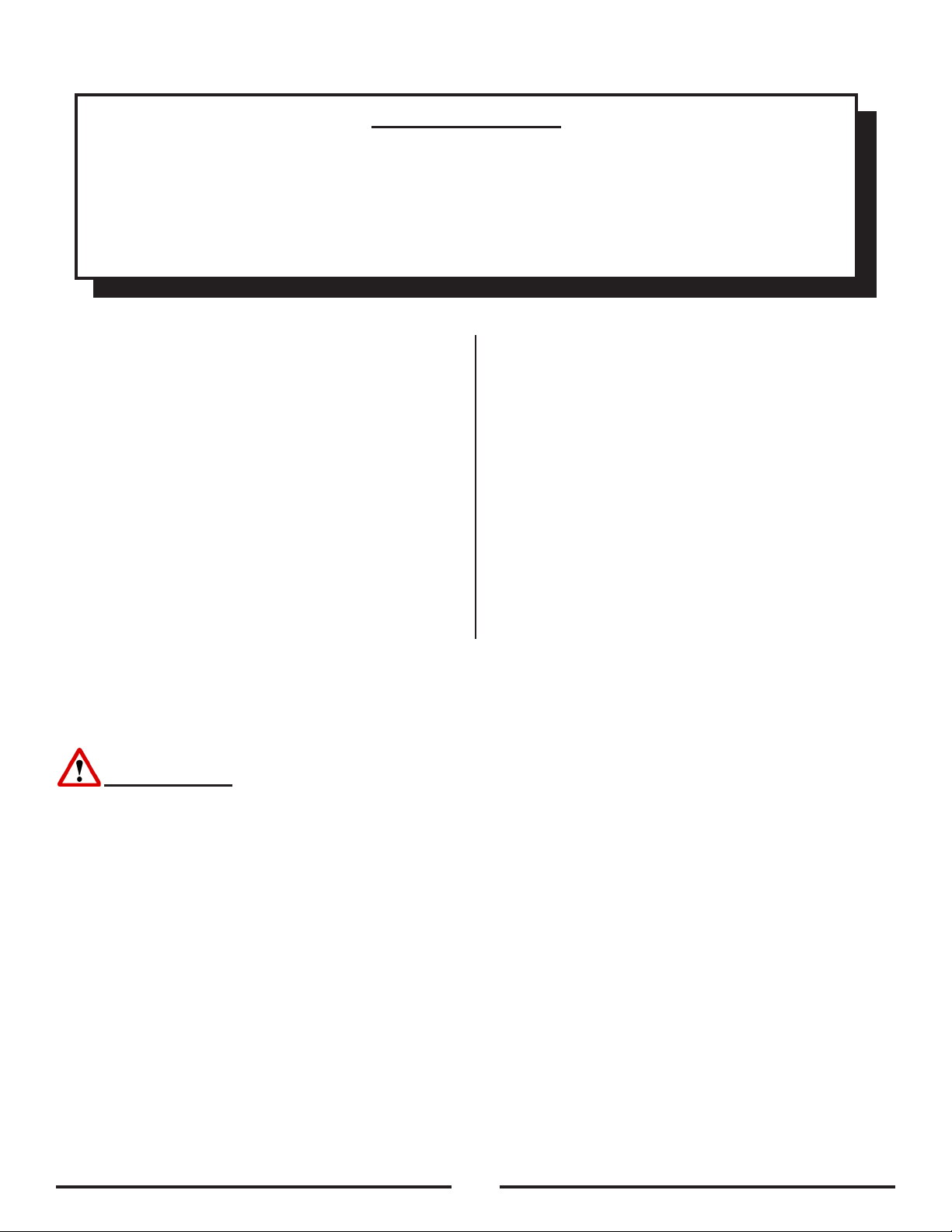
Safety Instructions
This floor-finishing machine shall be grounded while in
use to protect the operator from electrical shock. The
machine is provided with a three-conductor cord and
a three contact grounding attachment plug to fit the
proper grounding type receptacle. The green (or green
and yellow) conductor in the cord is the grounding wire.
Never connect this wire to other than the grounding pin
of the attachment plug.
This machine is for use on a nominal 230 volt circuit
and has a grounding plug that resembles the plug
illustrated as (A) in the sketch. Make sure that the
machine is connected to an outlet having the same
configuration as the plug. No adapter should be used
with this machine.
Model Super 7R Super 7R
Model Number 07098A 07099A
Voltage / Frequency 230V / 50Hz 230V / 50Hz
Amperage (A) 6 6
Motor 0.75 kW
750 Watts
0.75 kW
750 Watts
Abrasive Size 7” X 7/8” Disc 7” X 7/8” Disc
Disc Rate 2800 2800
Disc Driver System Gear Driven Gear Driven
Power Cable H05V/F3G 1.0mm sq X 15.4m H05V/F3G 1.5mm sq X 15.4m
Dust Collection Standard Standard
Dust Control Rate 110 CFM 110 CFM
Machine Specifications
10
Dust Collection
This sanding machine is designed to be operated with
a remote vacuum dust collection system or with the
included dust bag
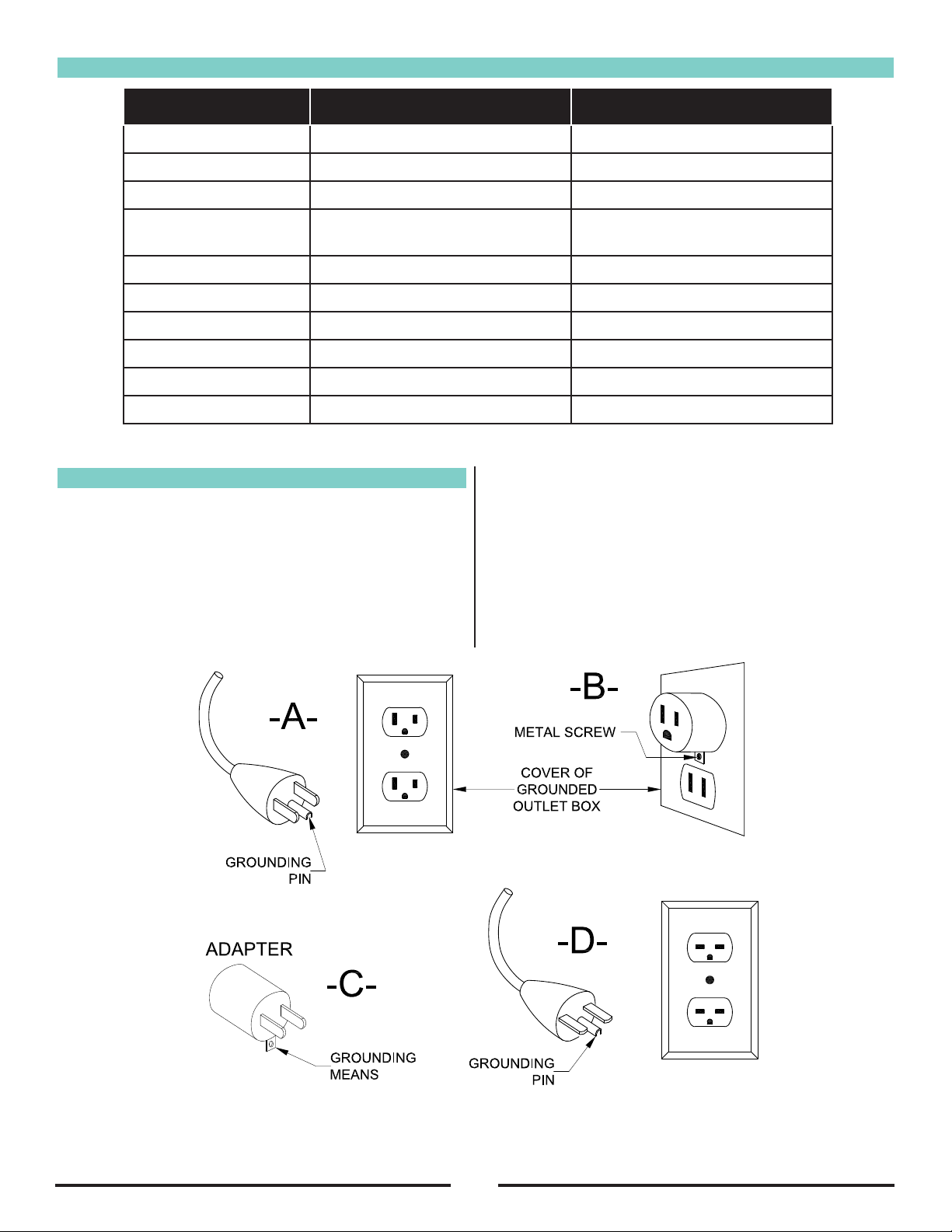
Preparing Remote Vacuum Dust Collection Systems
To prepare the machine for remote vacuum dust
collection systems that have a 2” hose end, follow this
procedure:
1. Install 2” hose end (Figure 1 - A) directly into the
exhaust tube (Figure 1 - B).
2. The exhaust tube can be rotated for optimum
convenience.
To prepare the machine for remote vacuum dust
collection systems that have a 1-1/2” hose end, follow
this procedure:
1. Install 2” hose end (Figure 1 - A) directly into the
exhaust tube (Figure 1 - B).
2. The exhaust tube can be rotated for optimum
convenience.
NOTE: Start the remote vacuum collections system
before operation.
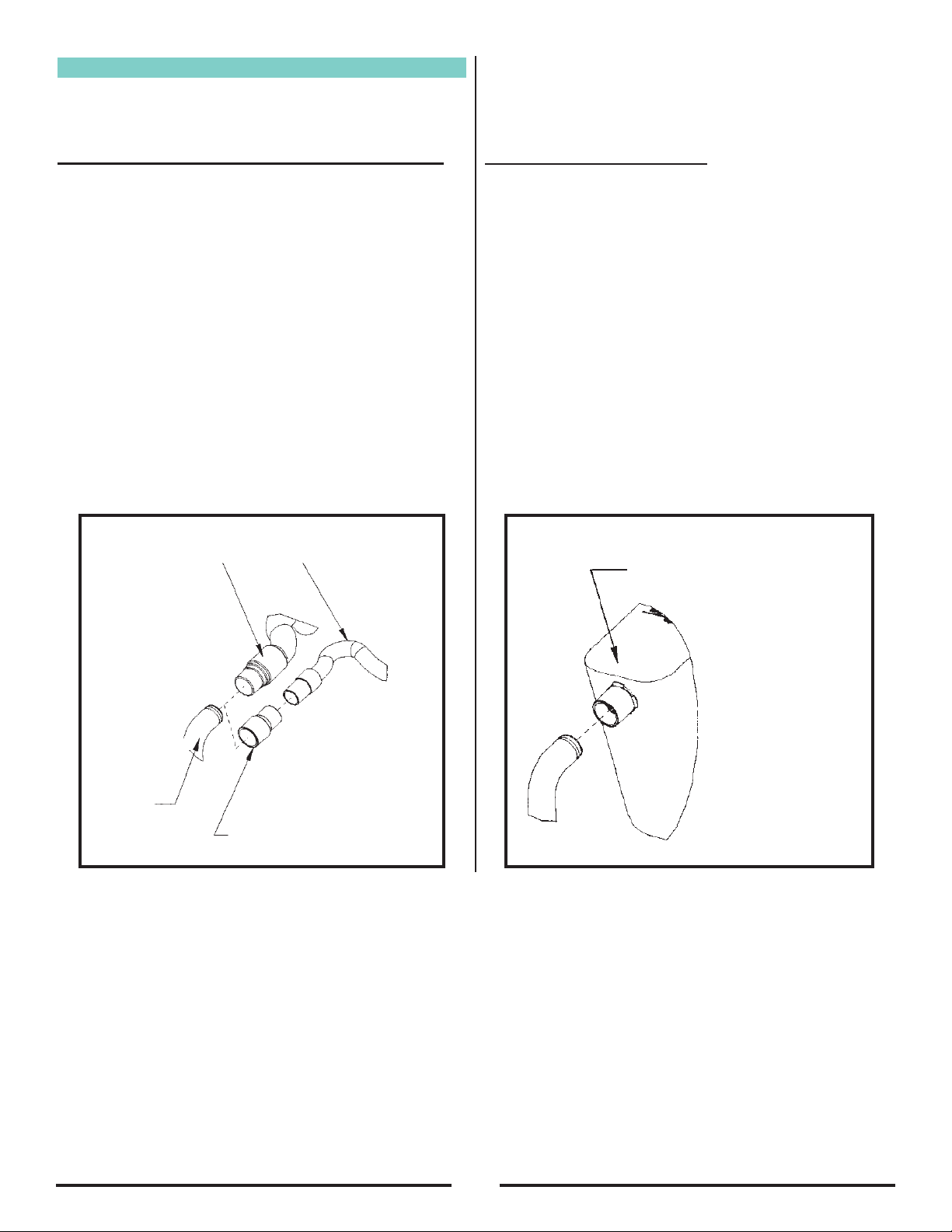
Preparing Using the Dust Bag
To prepare the machine for use with the included dust
bag (Part No.53544B), follow this procedure:
1. Install the dust bag by pressing the end onto the
exhaust tube until the ring locks into the groove
(Figure 2). This is best done by pressing on the
back of the bag opening with the palm of your
hand.
2. The exhaust tube can be rotated for optimum
convenience.
3. To remove the dust bag from the exhaust tube, pry
up the end of the bag opening to partially release
the internal rib from the groove, then pull.
4. To empty the dust bag, unzip the disposal flap and
force contents out by inverting the bag.
NOTE: For best results, empty frequently. Follow all
warnings posted in this manual and on the dust bag.
Figure 2
Install the dust bag by pressing the
end onto the exhaust tube until the
ring locks into the groove.
C
D
1-1/2” Hose from
Vacuum System
(Not included)
2” Hose from Vac-
uum System
(Not included)A
(30563A)
2” Tube X 1-1/2”
Hose Adapter
B
Exhaust
Tube
Figure 1
11
Machine Set-Up
Preparing the Machine for Operation
1. Familiarize yourself with the machine. Read all
danger, warning, and caution statements and the
Owner’s Manual before operating this machine. If
you or your operator cannot read English, have this
manual explained fully before attempting to operate
this machine.
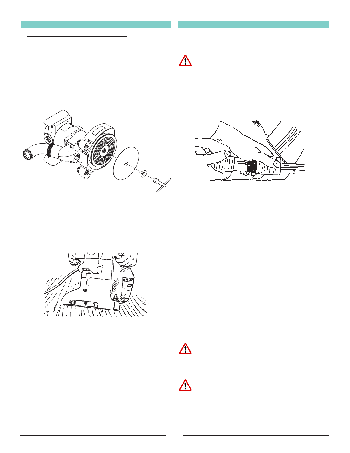
2. Remove screw and abrasive retainer. Center
abrasive on pad and secure with abrasive retainer
and screw. (Figure 3)
3. Return machine to upright position and tilt machine
back on casters until it comes to rest on the
exhaust bracket. Machine will be in a reclined
position. Do not allow machine to rest on pad
especially after use, or compression set may take
place within elastomer on pad. This will create a
at spot and bounce during use. (Figure 4)
Operating Instructions
1. Move machine to the location of your work. Set
any exposed nails with hammer and punch to avoid
encounter with abrasive.
WARNING: Bodily injury could occur if power is
applied to the machine with the power switch already
in the “ON” position. Always check to assure that the
power switch is in the “OFF” position before applying
power to the power cable.
2. Make sure the control switch is in the “Off” position
then connect the supply cable to an appropriately
grounded fused circuit. Connect the supply cable to
the motor pigtail. (Figure 5)
3. With the machine in the reclined position rmly
grasp both handles and ip the control switch to the
“ON” position. (Figure 4.)
4. Gradually lower pad to surface intended for
sanding. Make sure the machine is in motion
while the pad is engaged with the surface to be
sanded. You may use broad circular motion as
you sand along the length of the surface or your
may use a combination of forward and sidewards
motions. In time you will develop your own
technique to optimize coverage and dust recovery.
It is advisable to not add effort to the pad as this
may lead to “nosing in” or “tipping” which produces
grooves or lines on the surface.
5. When replacing abrasive, emptying the contents of
the dust bag, or sanding operation is completed,
return machine to reclined position, ip control
switch to “Off” then disconnect the motor pigtail
from the supply cable.
6. Empty dust bag whenever it becomes 1/3 full.
DANGER: Failure to disconnect the supply cable
from machine whenever servicing, replacing abrasive,
or emptying the dust bag could result in electrocution
or severe injury. Never leave machine unattended
while the supply cable is connected.
DANGER: Never leave dust bag unattended with
sanding dust in it. Sanding dust can spontaneously
ignite and cause a re or explosion. Empty dust bag
into a metal container, clear of any combustibles. Do
not empty content into a re. Do not overll dust bag.
Figure 3
Figure 4
Figure 5

12
A
B
Adjustment Procedures
Leveling
To level machine: Grasp caster adjusting screw “A”
with an appropriate tool (pliers etc.). Using a similar
tool, loosen locknut “B” with a counter clockwise
motion. (Figure 6).
Condition 1: Pad creates ridges on both edges or a
“hop” is experienced.
Rotate both adjusting screws equal amounts
clockwise. Tighten locknut’s and test on a piece
of plywood. Repeat procedure until condition is
corrected. We recommend you not exceed 1/8”
rotation for each attempt.
Condition 2: Pad creates a ridge on the tip of the pad.
Rotate both adjusting screws counter clockwise,
tighten locknut’s and test. Repeat procedure until
condition is corrected. Use only 1/8 rotation for each
attempt.
Condition 3: Pad creates a ridge on only one side of the
pad.
Either rotate the adjusting screw of the side effected
clockwise or rotate the adjusting screw opposite
counterclockwise, depending on whether the ridge
terminates beyond the tip of the pad or prior to it. If it
is prior to the tip, adjust the side effected, otherwise
adjust the opposite side.
Sanding Cuts & Sandpaper
Initial Cut:
The purpose of the initial cut is to remove old finish and
gross imperfections on the floor surface. Use a course
(20-36 grit) grain abrasive.
If glazing, loading, or burning takes place
immediately into an initial cut, select a coarser
abrasive. If this should occur during an initial cut, the
abrasive has dulled and must be replaced.
Final Cuts:
The purpose of a finishing cut is to remove the
scratches produced during the initial cut. Use a fine (60-
80 grit) grain abrasive.
If the surface remains rough after a finishing cut, it may
be necessary to use an even finer grain of abrasive (80-
100grit). Care should be taken in selecting the grit size
of the abrasive. A very fine grain will close the pores
on a wood floor making admission of a stain difficult. If
glazing or burning should occur the abrasive has dulled
and must be replaced.
Routine Maintenance
CAUTION: Failure to perform maintenance at
recommended intervals may void warranty.
Carbon Brushes
Have the carbon brushes replaced at least every 500
hours and more frequently under heavy use.
Dust Bag
Periodically the dust bag should be turned inside out,
shaken vigorously and machine washed in cold water
to prevent pore blockage and loss of dust control.
Bearings
To insure reliable performance, have armature and
pad driver bearings inspected for wear or damage
after every 1500 hours. If used heavily, have the
bearings replaced seasonally.
Lubrication
The machine comes fully lubricated. The gears in the
gear box have enough lubrication for approximately
six months of normal operation. Have the lubricant
changed at least every 6 months or more frequently
under heavy use.
Figure 6
Maintenance
CAUTION: Maintenance and repairs performed
by unauthorized personnel could result in damage
or injury. Maintenance and repairs performed by
unauthorized personnel will void your warranty.
Failure to perform maintenance at recommended
intervals may void warranty.
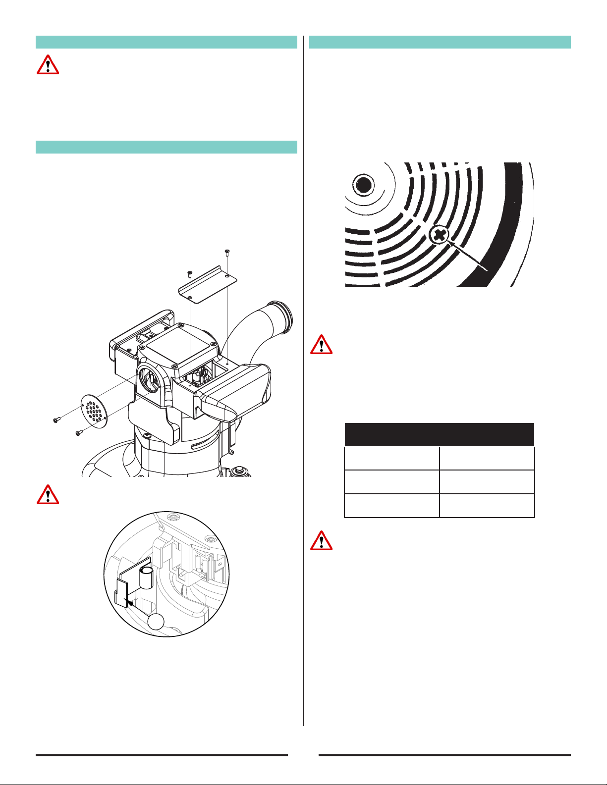
Carbon Brushes
Inspect all four brushes every 6 months or 250 hours.
Access to the brushes is gained through the front and
back motor vent plugs and under both motor covers
(Figure 7). Press tab (A) on spring clip assembly in,
rotate, then remove (Figure 8).Use needle-nose pliers to
disconnect the shunt wire. If any brush has worn to 3/8”
in length or shorter, replace the entire set.
CAUTION: Use only motor brush PN 40818A or PN
40055A with shunt wire or motor failure will occur.
When replacing the brushes make sure that the brush
seats against the commutator, the spring rest in the
recess of the brush, and the brush is free to travel.
When returning the switch cover, keep any wires clear of
the commutator and any pinch site.
Gearbox Lubricant
To change the lubricant in the gearbox, follow this
procedure:
1. Put the machine upside down on a bench.
2. Align one of the two holes in the rubber pad with
one of the three holes in the rotating wall guard.
3. Align both holes with one of the three screws in the
gear housing cover. Remove the screw from the
gear housing cover. (Figure 9)
4. Align the holes with each of the other two screws,
then remove screws.
CAUTION: Make sure no dust enters the gear box.
Damage will occur to the gear box.
5. Remove the cover from the gear housing.
6. Remove the old lubricant from the gearbox.
7. Add six ounces of American Sanders Technology
lubricant to the gear box.
CAUTION: To prevent damage to the motor, do not
add more than six ounces of lubricant to the gearbox.
8. Using the three screws removed above, install the
cover on the gear housing.
9. Start the machine and let it run for 15 minutes. A
small amount of excess lubricant should ow out
the vent hole. If none appears it may be necessary
to add additional lubricant.
10. Wipe off excess lubricant and clear vent hole.
13
A
Figure 8
Figure 7 Figure 9
Lubricants
Quantity Part Number
1 Quart 16610A
1 Gallon 16611A

14
Super 7R Australia
Edger
Parts Manual
Notes:
________________________________________________
________________________________________________
________________________________________________
________________________________________________
________________________________________________
________________________________________________
________________________________________________
________________________________________________
________________________________________________
________________________________________________
________________________________________________
________________________________________________
________________________________________________
________________________________________________
________________________________________________
________________________________________________
________________________________________________
________________________________________________
________________________________________________
________________________________________________
________________________________________________
________________________________________________
________________________________________________

Electrical Schematic
15

16
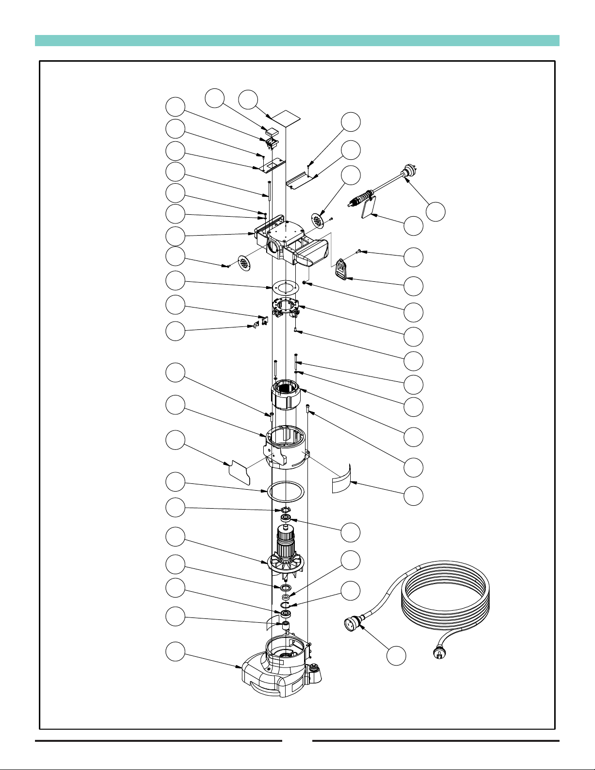
Lower Assembly
RF062000 070116
24
27
34
29
32
40
34
30
9
10
13
11 812 19 17
18
16
15
33
1720
22
21
23
1
2
35
3
36
25
35
31
26
4
38
28
5
37
6
7
14
39

Lower Assembly (continued)
17
Item Ref. No. Description Qty
1 318303 SPRING, LOAD 1
2 307702 SHAFT, DRIVE, GEAR 1
3 915028 KEY, WOODRUFF, 1/8” X 5/8” 1
4 87609A WASHER, SEAL 3
5 317204 DISC, GUARD, RETAINER 1
6 21066A DISC, SANDING 1
7 960125 CLAMP, ABRASIVE 1
8 980603 WASHER, LOCK, #10 1
9 293406 GASKET, EXHAUST 1
10 962289 BOLT, SH, 1/4” X 3/4” 4
11 302101 CLIP, STEEL 1
12 962987 SCREW, PH, #10 X 3/8” 1
13 987300 WRENCH, CLAMP SCREW 1
14 310803 BRACKET, SUPPORT, CASTER 2
15 920670 NUT, LOCK, ADJUST 2
16 960130 SCREW, SWIVEL, CASTER 2
17 50740A BEARING, BALL, 1/4” X 3/4” 4
18 298215 COLLAR, SPACING 2
19 85702A BOLT, HEX, 1/4” X 1-3/4” 2
20 10212A WHEEL & YOKE, ASM. 2
Item Ref. No. Description Qty
21 316804 PLUG, PIPE 1
22 56380216 DECAL, CAUTION 1
23 56380639 DECAL, PROP 65 1
24 53544B BAG, DUST 1
25 303502 GEAR, DRIVE 1
26 302306 COVER, HOUSING, ASM. 1
27 30563A ADAPTER, HOSE, 1.50” X 2.00” 1
28 293616 GUARD, DISC 1
29 61564A TUBE, EXHAUST 1
30 21077A ADAPTER, EXHAUST 1
31 34232A GASKET, CASE, GEAR 1
32 AS009900 NUT, SLIP, JOINT, LOCK (07098A) 1
80276A NUT, SLIP, JOINT, 2 X 2 (07099A)
33 962109 SCREW, PH, #10 X 5/8” 4
34 30613A SEAL, PIPE 2
35 902550 BEARING, BALL, 6203 2
36 L067304 RING, RETAINING 1
37 962974 SCREW, PH, #6 X 1/2” 4
38 84808A SCREW, PH, #10 X 3/4” 3
39 980088 WASHER, FIBER 2
40 NB072400 SCREW, SET, 1/4” X 3/16” (07098A) 1
[ ] 31407A CASE, EDGER, SUPER 7R 1
* 30666A WHEEL & YOKE URETHANE EDGERS 1
* 10827A EXHAUST CONVERSION KIT S-7R 1
* 38728A DISC CONV HOOK 6-7/8 10ea/BX 1
[ ] = not shown
* = optional, not shown
RF062100 072018
18
39
12
26
20
14
13
29
12
27
33
37
35
36
28
31
6
9
10
5
21
4
32
11
17
1
3
2
16 23
15
34
1
22
30
25
38
UPPER ASSEMBLY FOR
07098A
24
19
8
7
40
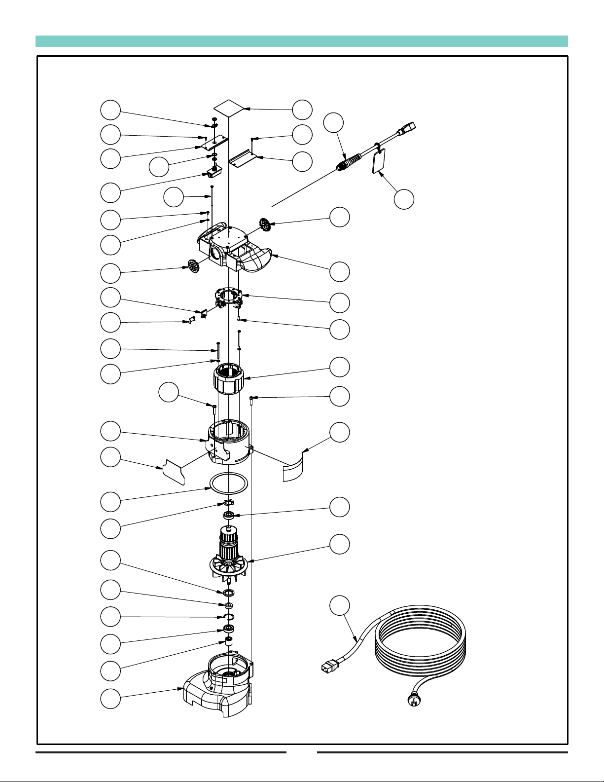
Upper Assembly (07098A)
18

Upper Assembly (07098A) (continued)
19
Item Ref. No. Description Qty
1 902567 BEARING BALL DOUBLE
SEALED
2
2 10110A ARMATURE ASM SUPER 7R
240V 50
1
3 298306 SPRING, LOAD, 56 1
4 962454 SCREW, 1/4 - 20 X 1, SC ST CAP 2
5 962988 SCREW, 1/4-20 X 1-1/4, PN, ST,
PH
1
6 962727 SCREW, 8-32 X 1/2 PN ST TP23
PH
4
7 980643 WASHER, 7/16” OD X .036 THK 2
8 962211 SCREW, 10-24 X 2.5, RD P ST 2
9 40055A BRUSH, CARBON 4
10 50932A SPRING BRUSH HOLDER 4
11 293403 GASKET, EXHAUST FAN,
BAFFLE
1
12 962545 SCREW, 6-32 X 3/8, FLAT HD 4
13 980621 WASHER, LOCK, EXTERNAL
TOOTH
1
14 962550 SCREW, 8-32 X 5/16 1
15 407302 RING, RETAINING 1
16 297604 OIL SEAL 92 1
17 73285A LABEL, WARNING 1
18 AS014300 NAMEPLATE, AMERICAN
SANDERS, 3”
1
19 304204 HOUSING, GEAR 1
Item Ref. No. Description Qty
20 962404 SCREW, 10-24 X 3-1/4, FH, ST,
PH
4
21 AS013500 FIELD & COIL, SUPER 7R, ASM.,
240V
1
22 293514 PINION, ARMETURE 1
23 308202 SPACER, BEARING 1
24 304208 HOUSING AND GUARD ASSEM 1
25 AS009800 COVER AND HANDLE ASM.,
AUST.
1
26 AS008700 COVER, MOTOR, BRUSH,
SWITCH
1
27 AS008800 COVER, MOTOR, BRUSH, LH,
AUST.
1
28 AS007200 RING, INSULATOR, BRUSH
HOLDER
1
29 962330 SCREW 6-32 X 3/8 PAN HD 4
30 AS008100 PLUG, VENT, PLATE 2
31 AS015000 HOLDER, BRUSH, SUPER 7R,
ASM., AUST.
1
32 AS014900 NAMEPLATE, FRONT, SUPER 7R 1
33 AS008200 CORD, SANDER, PIGTAIL, AUST. 1
34 AS008300 CORDSET, 49 FEET, AUST. 1
35 AS009000 HOOK, TETHER, CORD,
SUPPORT
1
36 NB9640 SCREW, PAN HEAD, #10-32 UNF,
X 3/4
1
37 NB9735 NUT, LOCK, 10-24, NYLON 1
38 70175A TAG WARNING ENG-SPN 1
39 AS020500 SWITCH, ROCKER, HIGH
INRUSH
1
40 AS033800 COVER, ROCKER SWITCH 1
20
Upper Assembly (07099A)
RF067300 040417
UPPER ASSEMBLY FOR
07099A
17
12
33
36
22
18
27
12
32
29
21 20
14
13
18 28
31
6
9
10
8
7
23
4
26
30
35
11
3
1
2
16
25
24
1
15
34
5
19
Table of contents
Other Amano Edger manuals

Amano
Amano American Sanders COMPASS HDTR User manual

Amano
Amano American Sanders Compass User manual

Amano
Amano American Sanders EZ-E User manual

Amano
Amano AMERICAN SANDERS 07222A User manual

Amano
Amano American Sanders Super 7R Australia User manual

Amano
Amano 07125A User manual

Amano
Amano American Sanders 07246A User manual

Amano
Amano 07208A User manual


