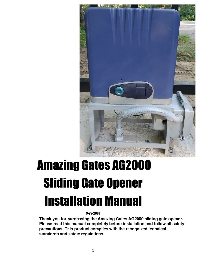
Amazing Gates 1000 User manual

1
Amazing Gates 1000
Sliding Gate Opener
Installation Manual
7-16-2020

2
Thank you for purchasing the Amazing Gates 1000 sliding gate opener. Please read this manual completely
before installation and follow all safety precautions. This product complies with the recognized technical
standards and safety regulations.
General Safety
WARNING! Incorrect installation or improper use of this product can cause damage to people,
animals or property.
This equipment is similar to other gate or door equipment and meets or exceeds
Underwriters Laboratory Standard 325 (UL 325). However, gate equipment has
hazards associated with its use and therefore by installing this product the installer
and user accept full responsibility for following and noting the installation and
safety instructions. Failure to follow installation and safety instructions can result
in hazards developing due to improper assembly. You agree to properly install this
product and that if you fail to do so Amazing Gates of America, LLC (“AGA”) shall in no event
be liable for direct, indirect, incidental, special or consequential damages or loss of
profits whether based in contract tort or any other legal theory during the course
of the warranty or at any time thereafter. The installer and/or user agree to assume
responsibility for all liability and use of this product releasing Amazing Gates of America, LLC
from any and all liability. If you are not in agreement with this disclaimer or do not
feel capable of properly following all installation and safety instructions you may
return this product for full replacement value.
READ ALL INSTRUCTIONS CAREFULLY AND COMPLETELY before attempting to
install and use this automatic gate operator. This gate operator produces a high level
of force. Stay clear of the unit while it is operating and exercise caution at all times. All automatic gate
operators are intended for use on vehicular gates only. This product meets and exceeds the
requirements of UL 325, the standard which regulates gate operator safety, as established and made
effective March 1, 2000, by Underwriters Laboratories Inc.
• Discard packing materials (plastic, cardboard, polystyrene etc.) according to the provisions set out by current
standards. Keep nylon or polystyrene bags out of children’s reach.
•This product was exclusively designed and manufactured for the use specified in the present
documentation. Any other use not specified in this documentation could damage the product and be
dangerous.
• The factory declines all responsibility for any consequences resulting from improper use of the product, or
use which is different from that expected and specified in this manual.
• Do not install the product in an explosive atmosphere.
• The factory declines all responsibility for any consequences resulting from failure to observe good technical
practices when constructing gates as well as from any deformation of the gate which might occur during use.
• Disconnect the electrical power supply before carrying out any work on the installation. Also disconnect
any back-up batteries, if included.
• Check that a differential switch with a 0.03A threshold is fitted just before the power supply mains.
• Check that grounding is carried out correctly: connect gates and system components to a ground terminal.
• Fit all the safety devices (photo beams, safety edges, etc.) which are needed to protect the area from any
danger caused by squashing, conveying and shearing.
• Display a warning sign at the gate.
• The factory declines all responsibility with respect to the automation safety and correct operation when
other supplier’s components are used.
• Only use original parts for any maintenance or repair operation.

3
• Do not modify the automation components, unless explicitly authorized by the factory.
• Instruct the product user about the control systems provided and the manual opening operation in case of
emergency.
• Keep children away from automatic gates.
• Keep remote transmitters or other control devices out of children’s reach, in order to avoid unintentional
automatic activation.
• Repairs should be made by qualified personnel only.
• Anything which is not expressly provided for in this manual is not allowed.
• Installation must be carried out using the safety devices and controls prescribed by the UL 325 standard.
Class Rating
The Amazing Gates 1000 Slide Operator is intended for use with vehicular slide gates in single family
residential applications. The operator is system certified to be in compliance with UL 325, current edition, as
of publication date.
Vehicular Gate Operator Class Categories:
Residential Vehicular Gate Operator—Class I: A vehicular gate operator (or system) intended for use in a
home of one-to-four single family dwelling, or a garage or parking area associated therewith.
Commercial/General Access Vehicular Gate Operator—Class II: A vehicular gate operator (or system)
intended for use in a commercial location or building such as a multifamily housing unit (five or more single
family units), hotel, garages, retail store, or other building servicing the general public.
Industrial/Limited Access Vehicular Gate Operator–Class III: A vehicular gate operator (or system)
intended for use in an industrial location or building such as a factory or loading dock area or other locations
not intended to service the general public.
Restricted Access Vehicular Gate Operator–Class IV: A vehicular gate operator (or system) intended for
use in a guarded industrial location or building such as an airport security area or other restricted access
locations not servicing the general public, in which unauthorized access is prevented via supervision by
security personnel.
Technical Specifications & Features
Specifications:
•Motor: 24VDC
•Absorbed motor power: 370W
•Gate moving speed: 7.9“/second
•Max gate weight: 1100 lbs
•Max torque: 18.44 ft lb/f
•Environmental conditions: From 5°F to 104°F
•Protection class: IP44
•Dimensions: 11-1/2” x 7.5” x 19.5” (L*W*H)
Features:
•Easy to install and low maintenance
•Quick selection for gate open/close direction
•Get the desired chain tension by adjusting the chain bolts
•Home-link compatible technology

4
•Emergency release key in case of power failure
•Stop/Reverse in case of obstruction during gate opening/closing
•Built in adjustable auto-close
•Reliable inner mechanical limit switch for easy and accurate setting
•Can be equipped with wide range accessories
Important Safety Instructions
Safety Instructions for Installation
A. Install the gate opener only when:
1) The opener is appropriate for the construction of the gate and the usage Class of the gate,
2) All openings of a horizontal slide gate are guarded or screened from the bottom of the gate to a minimum of 4
feet (1.22 m) above the ground to prevent a 2-1/4 inch (57.2 mm) diameter sphere from passing through the
openings anywhere in the gate, and in that portion of the adjacent fence that the gate covers in the open
position, 3) All exposed pinch points are eliminated or guarded.
4) Guarding is supplied for exposed rollers.
B. The opener is intended for installation only on gates used for vehicles. Pedestrians must be supplied with a
separate access opening. The pedestrian access opening shall be designed to promote pedestrian usage.
Locate the gate such that persons will not come in contact with the vehicular gate during the entire path of travel
of the vehicular gate.
C. The gat--------------------e must be installed in a location so that enough clearance is supplied between the gate
and adjacent structure-es when opening and closing to reduce the risk of entrapment.
D. The gate must be properly installed and work freely in both directions prior to the installation of the gate opener.
Do not over-tighten the opener clutch or pressure relief valve to compensate for a damaged gate.
E. For gate openers utilizing Type D protection:
1) The gate opener controls must be placed so that the user has full view of the gate area when the gate is moving.
2) The placard provided marked in letters at least 1/4-in (6.4-mm) high with the word ″WARNING″ and the
following statement or the equivalent: “ Moving Gate Has the Potential of Inflicting Injury or Death – Do Not
Start Gate Unless Path is Clear” shall be placed adjacent to the controls,
3) An automatic closing device (such as a timer, loop sensor, or similar device) shall not be employed.
4) No other activation device shall be connected.

5
F. Controls intended for user
activation must be located
at least ten feet away from
any moving part of the gate
and where the user is
prevented from reaching
over, under, around or
through the gate to operate
the controls. Outdoor or
easily accessible controls
shall have a security
feature to prevent
unauthorized use.
G.The Stop and/or Reset button must be located in the line-of-sight of the gate. Activation of the reset control shall
not cause the opener to start.
H. A minimum of two (2) WARNING SIGNS shall be installed, one on each side of the gate where easily visible.
1) See instructions on the placement of non-contact sensors for each Type of application,
2) Care shall be exercised to reduce the risk of nuisance tripping, such as when a vehicle trips the sensor while the
gate is still moving in the opening direction.
3) One or more non-contact sensors shall be located where the risk of entrapment or obstruction exists, such as
the perimeter reachable by a moving gate or barrier.
I. For a gate opener utilizing a contact sensor in accordance with Usage Class:
1) One or more contact sensors shall be located where the risk of entrapment or obstruction exists, such as at the
leading edge, trailing edge, and post-mounted both inside and outside of a vehicular horizontal slide gate.
2) One or more contact sensors shall be located at the bottom edge of a vehicular vertical lift gate.
3) One or more contact sensors shall be located at the pinch point of a vehicular vertical pivot gate.
4) A hardwired contact sensor shall be located and its wiring arranged so that the communication between the
sensor and the gate opener is not subjected to mechanical damage.
5) A wireless contact sensor such as one that transmits radio frequency (RF) signals to the gate opener for
entrapment protection functions shall be located where the transmission of the signals are not obstructed or
impeded by building structures, natural landscaping or similar obstruction. A wireless contact sensor shall
function under the intended end-use conditions.
6) One or more contact sensors shall be located on the inside and outside leading edge of a sliding gate.
Additionally, if the bottom edge of a sliding gate is greater than 6 inches (152 mm) above the ground at any point in
its arc of travel, one or more contact sensors shall be located on the bottom edge.

6
Installation Overview
Installation of the Opener
Caution
➢Be sure that the opener is installed in a level and paralleled position and is
properly secured.
➢Improper installation could result in property damage, severe injury, and/or
death.
➢Before starting installation, ensure that there is no point of friction during
the entire movement of the gate and there is no danger of derailment.
➢Ensure that the Warning Signs are present.

7
Necessary Tools:
The following tools may be necessary to install the Gate Opener.
➢Screwdrivers
➢Electric drill
➢Wire cutters
➢Wire stripper
➢A socket set
The recommended power for this gate operator system is 110-120V AC. The integrated
transformer steps the power down to 24Vdc to operate the control panel and operator arms.
Please make sure to shut off the power before installation or maintenance. The
installation of the 110V AC power supply cable to the Control Box should be done by a
qualified professional electrician.
Alternatively, this system can be powered by batteries charged with a 24V solar panel. Two 12Vdc batteries
must be wired IN SERIES to provide 24Vdc.
Battery backup is not required. In the event of a power failure there is a manual release lever on the top of each
operator arm which allows the gates to be opened manually. Turn the key and lift the lever to move the gate
manually.
Battery backup may be added by installing two 12v 7ah batteries, wired in series to produce 24Vdc.
The cables for the safety photo beam, exit wand, wired keypad and wired intercom are not required to be placed
in conduit but it is highly recommended to do so in order to protect them and to be able to more easily replace
them.
It is highly recommended to ground the system with a grounding rod. Attach the grounding wire to the GND
connection.
Installation procedures
1. The default limit setting is for the gate in the closed position. Before installation, please make sure gate is
closed.
2. Prepare one or more conduits for the electrical cables. Cable conduits have to pass through the hole in the
base plate.
3. Put the base plate on the concrete pad but don’t bolt it down yet. This is only a temporary step. Further
adjustment will be required when installing the chain.

8
4. Make the chain go through the chain box. Attach the chain to the gate frame with the chain bolts and chain
brackets. (Bolts and brackets supplied in package.)
5. Mount the chain box to the base plate by using screws and washers, don’t make the four screws too tight.
6. Move the opener to the proper position. Attach the opener to a concrete platform with 4 expansion bolts
supplied in the package.
Manual Operation
The opener comes with a manual release in case of emergency
➢Insert the manual release key into the release lock, then turn the key clockwise 90 degrees
➢Pull out the release lock part way. Now the gear and shaft are disengaged
Installation of the Chain
1. Start with the gate in the closed position
2. The package contains 20 feet of #40 chain
3. Place one of the ends of the chain section on the top of the gear temporarily. Install the chain, connecting
one section at a time and make sure it is level. Mark the chain’s mounting holes on the gate before
fastening the screws onto the gate
4. Fit the chain with self-threading screws. Please keep 1/16-inch space between the chain and the gear to
keep the weight of the gate from affecting the opener
Refer
to
the
figures
below

9
Installation of the Limit Poles
The two magnetic limit devices mount on the gate. They tell the operator where to stop the gate.
When the gate is closed, the Blue North Pole lines up with the operator.
When the gate is open, the Red South Pole lines up with the operator.
Control Board Wiring
Diagram 6
1. ANT terminal: Antenna connection
2. PED terminal: Used for connecting an external device control for opening pedestrian mode. The
gate will open partially.
3. Infrared 2 terminal: Used for connecting a safety device like a photo eye. Infrared 2 is used for a
photo eye or safety edge in the BACK of the gate, so that when the gate is OPENING if something
blocks the beam the gate will stop. This protects from entrapment.
Diagram 7
Connect terminal ⑦ to the “COM” of photocell RX (receiver.)
Connect terminal ③to the “OUT” or “N.O.” of photocell RX (receiver.)
Terminals ⑩ and ⑪supply power for external devices such as photo eyes.

10
Connect terminal ⑩ to the “+” of photo eye RX and TX.
Connect terminal ⑪ to the “-“ of photo eye RX and TX.
4. Infrared 1 terminal: Used for connecting a safety device like a photo beam or an edge sensor.
The photo beam shoots across the driveway opening. If something blocks the beam or the
safety edge encounters pressure, the gate will stop and reverse.
Diagram 8
Connect terminal ⑦to the “COM” of photo eye RX.
Connect terminal ④to the “OUT” or “NO” of photo eye RX.
Terminals ⑩ and ⑪ supply power for external devices.
Connect terminal ⑩to the “+” of photo eye RX and TX.
Connect terminal ⑪to the “-” of photo eye RX and TX.
5.SWIPE CARD: Used for connecting a Swipe Card system, a Wired Keypad or an Exit Probe.
Diagram 9

11
Example for wired keypad:
Terminal ⑤ and ⑦ connect to wired keypad.
Terminal ⑩ and ⑪ to supply power for the wired keypad.
6. START Terminal: Single button control mode switch, used for controlling the gate “Open-Close-
Stop-Open-Close” cyclically. (Note: Holding the button for a long time may affect some other function.)
Diagram 9
Example for a push button;
Terminal ⑤ and ⑦ connect to push button.
Terminal ⑩ and ⑪ supply power for push button.
7. COM Terminal: Use for connecting a COM terminal or a GND connection.
8 & 9. Lamp terminal: Use for connecting an optional flashing light. Light flashes while gate is
running. Output voltage is DC24V
Diagram 11
Terminal ⑧ and ⑨ is for flashing light .
10 &11 +24V: Provides DC24V for external devices such as an infrared photo eye

12
12 & 13 UPS terminal: (Uninterruptible Power Supply) Used for connecting back up batteries, which
could be charged by the on-board electric power supply. The charging current is 20-50mA. The
batteries would supply power automatically when the power is out. When UPS is supplying power to
board, the standby current is 20mA, and the current is about 5-10A when the motor is running.
Diagram 12
The control board accepts 24VDC of battery power input. Therefore, connect two 12V batteries in
series to create 24V of current.
First connect battery 1 “+” to battery 2 “-”
Then connect battery 1 “-” to terminal ⑬
Then connect battery 2 “+” to terminal ⑫
14 & 13 Solar terminal: Use for connecting a solar panel.
Diagram 13 F
First connect two batteries to UPS as shown above.
Then connect terminals ⑬- and ⑭+ to the solar panel.

13
15 & 16. Motor Terminals: Use for connecting the 24VDC motor.
There are Two ways to wire the motor. From the INSIDE Looking Out, the gate can slide open to the
RIGHT or slide open to the LEFT.
A. Install the motor on the RIGHT side of driveway (factory setting)
From the Inside Looking Out, the gate SLIDES OPEN to the RIGHT
When the motor is being installed to right of gate, wire the motor as shown
Terminal 15: Connect the red wire from motor
Terminal 16: Connect the black wire from motor
B. Install the motor on the LEFT side of driveway
From the Inside Looking Out, the gate SLIDES OPEN TO THE LEFT
When the motor is being installed on the LEFT side of the driveway, wire motor as shown
Terminal 15: Connect the black wire from motor
Terminal 16: Connect the red wire from motor

14
17&18 24V Terminal:Used for connecting the 24VAC transformer
Diagram 16
Connect terminal ⑰ to one of the wires from the transformer
Connect terminal ⑱ to the other wire from the transformer
The two red wires from transformer are for connecting the 120VAC power supply
Ground the chassis with a grounding rod or with a third wire back to ground.
Program Remote Transmitters
Press the LEARN button on the Control Board for about 1 second, the indicator LED will
turn off when the board is in learn mode.
Press any button of the remote transmitter for about 2 seconds. If the programming is
successful, the indicator LED on the board will flash four times and the buzzer will sound
once.
Note: After you press the LEARN button, if you don’t press a button on the remote within
5 seconds, the indicator LED will turn on and the Control Board will exit the learn mode.
IMPORTANT - Test the Operator:To keep things simple, at this point it is recommended to
test the operator before installing other accessories such as a photo eye, exit sensor or keypad. This
will prevent installation problems by keeping the setup simple.
This is also a good tip whenever you are troubleshooting: Disconnect the accessories such as the
photo eye and exit sensor, make sure the gate is working, then connect the accessories again one at
a time and test.

15
Installing the AGA Wireless Keypad
AGA Wireless Keypad Programming
NOTE: Have the keypad in hand at the gate control box when programming. Do not mount keypad on
gooseneck mounting post yet.
Open the keypad with the included wrench and install the batteries. The alarm will sound.
Replace the cover on the keypad and the alarm will stop. If the keypad alarm does not stop, open the
keypad again and bend up the lever slightly.
RESET: When you have the keypad open, notice there is a small hole where you could insert a paper
clip. This is the reset switch. If you are having trouble programming, insert a paper clip for 5 seconds
and then start over.
Step 1: Program the keypad to the gate operator Enter 0000* to start programming mode.
(Expect one long beep)
(Note: 0000 is the default code for programming; see below for how to change it)
(Note: The blue backlight will light when in programming mode)
Press 55#; keypad will beep once to confirm
(This sends a signal to the receiver on the control board.)
Pres 01# for a single sliding gate
Immediately Press and release the Red Learn Button on the operator control board. The control board
will beep, and the digital display will show a number.
Step 2: Test using the default code
For a single gate press 1111# to activate the gate.
For a double gate press 2222# to activate the gates.
Step 3: Add a keypad code
Enter 0000* to enter programming mode (expect one long beep)
For a single sliding gate press 01# (expect one beep)
Enter the new 4-digit code followed by the # key; for example, 2020# (expect one long beep and one
short beep to confirm)
Keypad will automatically exit programming mode
Try the new code followed by the # key
If the code does not work, start over, and if it still does not work, reset the keypad
You may add a total of three keypad codes
Step 4: Mount the keypad on the gooseneck mounting post
Note: The keypad will fit better on the goose neck mounting post if you use a 4" x 5" piece
of Trex deck material as a mounting plate between the mounting plate and the keypad
How to change the programming code:
Enter the current programming code, for example 0000* (expect one long beep)
Press 69# (expect one short beep)

16
Key in new 4-digit installer code followed by the # key for example 4640#
(expect one long beep and one short beep)
Keypad will automatically exit programming mode
RESET: When you have the keypad open, notice there is a small hole where you could insert a paper
clip. This is the reset switch. If you are having trouble programming, insert a paper clip for 5 seconds
and then start over.

17
Installing Safety Photo Eyes
We offer two types of photo eyes: through-beam and reflective. A through-beam photo eye has a
wired transmitter on one side of the driveway and a wired receiver on the other side. A reflector photo
eye has a transmitter/receiver on one side of the driveway and a reflector on the other side.
For protection ACROSS the driveway use Normally Open
If the photo eye has a “jumper”, set the jumper to NO (Normally Open.)
Connect Out/N.O. (Black) on the photo eye to IR1 (4) on the control board.
Connect Power + (Brown) on the photo eye to 24v (10) on the control board.
Connect Negative –(Blue) on the photo eye to COM (11) on the control board.
Connect Common (Yellow) on the photo eye to COM (7) on the control board.
(All Commons and Negatives from all photo eyes connect to the same terminal COM (7) on the control
board.)
White wire is not used
For protection BEHIND the gate use Normally Closed
If the photo eye has a “jumper”, set the jumper to NC (Normally Closed)
Connect Out/N.C. (White) on the photo eye to IR2 (3) on the control board.
Connect Power + (Brown) on the photo eye to 24v (10) on the control board.
Connect Negative –(Blue) on the photo eye to COM (11) on the control board.
Connect Common (Yellow) on the photo eye to COM (7) on the control board.
(All Commons and Negatives from all photo eyes connect to the same terminal COM (7) on the control
board.)
Black wire is not used
Test the photo eyes by activating the gate and then blocking the beam.
The gate will reverse. The gate will stay open as long as the beam is blocked.
As soon as the beam is no longer blocked, the gate will begin closing in 2 seconds.
IR1 vs IR2. IR1 is for protecting the area where the gate is closing towards. IR2 is for protecting the
area where the gate is opening towards.

18
INSTALLING AN AUTOMATIC EXIT SENSOR
(Also known as an Exit Wand or Exit Probe) An automatic exit sensor is buried alongside the driveway
and uses the earth’s magnetic field to detect moving metal. When the field is disturbed the gate is
triggered to open.
Dig a shallow trench and bury the exit sensor. It is not necessary to use a PVC conduit, but it is a good
idea in order to protect it and to make it easier to replace.
NOTES:
- Wire the exit sensor LAST after testing gate with remotes and keypad and photo beams
- Connect exit sensor with Power OFF
- When you Power ON, the exit sensor will calibrate and signal the gate to open
- P4 Function controls auto close time after SWIPE; changing it to “0” turns off auto close
Wiring Instructions for Exit Sensors:
Amazing Gates Exit Probe
Blue --- “SWIPE” (5)
Green --- “COM” (7)
Red --- “24Vdc” (10)
Black--- “GND” (11)
Yellow (not used)
Cartel Exit Probe
Blue --- “SWIPE” (5)
Black --- “COM” (7)
Red --- “24V” (10)
Shield/bare wire --- COM (11)
Green (not used)
EMX Exit Probe
Brown --- “SWIPE” (5)
Black & Green--- “COM” (7)
Red --- “24V” (10)
White (not used)

19
Wiring a Timer
N.O. --- “SWIPE” (5)
Com --- “COM” (7)
Power + --- “24V” (10)
Power - --- “GND” (11)
Note: Programming P4 controls auto close time seconds after SWIPE; changing it to “0” turns off auto
close.
Installing a Wired Keypad or Intercom
A wired keypad or an intercom can activate the gate by a relay which is two wires completing a circuit.
They can get their power from their own transformer plugged into a 110V AC power source or they
can get their power from the operator control board.
Wired Keypad Wiring Guide:
Relay or N.O. --- “START” (6)
COM --- “COM” (7)
Positive + --- “24V” (10)
Negative - --- “GND” (11)
(Could also use “SWIPE” instead of “START”but then you can’t close the gate by keying in the code
again.)
Installing a Radio Receiver
The control board includes its own radio receiver, and two remotes come with the system.
In some cases, you might want to add another receiver, for example if you want to use a different
wireless keypad such as the Liftmaster KPW5. In that case you could add the Liftmaster 850LM
receiver.
Wiring instructions for a radio receiver:
Liftmaster 850LM Radio Receiver
N.O. --- “START” (6)
COM --- “COM” (7)
Negative --- “COM” (11)
Positive --- “24V” (10)

20
Diagram 16
Control Board Functions and Settings
Status Indicator LED
When the board has power, the status indicator LED is lit
Motor open-close
instruction
The Blue LED lit up means the gate is Opening
The Red LED lit up means the gate is Closing
Remote Transmitters
Encoding format: Proprietary rolling code. Maximum Capacity is 120
transmitters.
In single button control mode, you can cycle through the operations of
“open-stop-close-open”. P8 = 1
The board can be customized to work with the EV1527 remote (you have
more control with three remote buttons). P8 = 0
The three buttons on the remote control can be used to open, close and
stop the gate.
Table of contents
Other Amazing Gates Gate Opener manuals
Popular Gate Opener manuals by other brands

Topens
Topens CK500 user manual

Chamberlain
Chamberlain Estate Series X1 LiftMaster Professional Replacement instructions

RIB
RIB MAGIC 105 manual

CAME
CAME BX704AGS installation manual

Heras
Heras Cloud Unit user manual

Roger Technology
Roger Technology H21 Series INSTRUCTIONS AND RECOMMENDATIONS FOR THE INSTALLER