manuals.online logo
Brands
  1. Home
  2. •
  3. Brands
  4. •
  5. Erreka
  6. •
  7. Gate Opener
  8. •
  9. Erreka BUL BL33 Operating instructions

Erreka BUL BL33 Operating instructions

Other Erreka Gate Opener manuals
Erreka ARES Series User guide

Erreka

Erreka ARES Series User guide

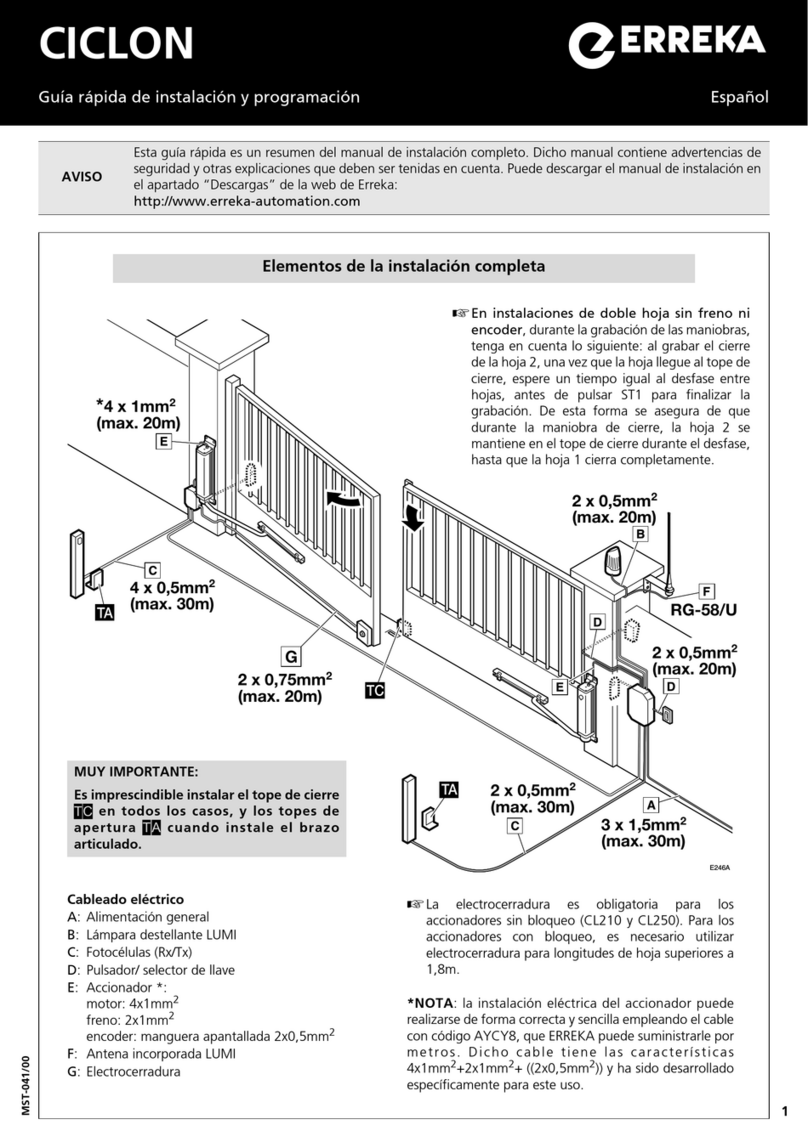
Erreka CICLON Operating instructions

Erreka

Erreka CICLON Operating instructions

Erreka KAIROS MSB-027/01 User manual

Erreka

Erreka KAIROS MSB-027/01 User manual

Erreka TORO KM1800 Operating instructions

Erreka

Erreka TORO KM1800 Operating instructions

Erreka ARC Series User guide

Erreka

Erreka ARC Series User guide

Erreka ARC Series User guide

Erreka

Erreka ARC Series User guide

Erreka Puma Operating instructions

Erreka

Erreka Puma Operating instructions

Erreka NAOS Operating instructions

Erreka

Erreka NAOS Operating instructions

Erreka MAGIC Operating instructions

Erreka

Erreka MAGIC Operating instructions
Erreka CICLON User guide

Erreka

Erreka CICLON User guide

Erreka MAGIC User guide

Erreka

Erreka MAGIC User guide

Erreka V2 CICLON User manual

Erreka

Erreka V2 CICLON User manual

Erreka TEMIS User manual

Erreka

Erreka TEMIS User manual

Erreka PUMA-I Operating instructions

Erreka

Erreka PUMA-I Operating instructions

Erreka TOPO User guide

Erreka

Erreka TOPO User guide

Erreka CA53 Operating instructions

Erreka

Erreka CA53 Operating instructions

Erreka CAT Operating instructions

Erreka

Erreka CAT Operating instructions

Erreka DINGO Operating instructions

Erreka

Erreka DINGO Operating instructions

Erreka MAGIC Operating instructions

Erreka

Erreka MAGIC Operating instructions

Erreka AXIL Series User manual

Erreka

Erreka AXIL Series User manual

Erreka PUMA-I Operating instructions

Erreka

Erreka PUMA-I Operating instructions

Erreka IZAR User guide

Erreka

Erreka IZAR User guide

Erreka LINCE Operating instructions

Erreka

Erreka LINCE Operating instructions

Erreka CALYPSO Series User manual

Erreka

Erreka CALYPSO Series User manual
Popular Gate Opener manuals by other brands

Nortek Security & Control Mighty Mule HD272 installation manual

Nortek Security & Control

Nortek Security & Control Mighty Mule HD272 installation manual

tousek TURN 10 Installation and operating instructions

tousek

tousek TURN 10 Installation and operating instructions

SOMFY AXOVIA 220B RTS installation instructions

SOMFY

SOMFY AXOVIA 220B RTS installation instructions

Nice HySecurity CBOX1050 Installation and programming manual

Nice HySecurity

Nice HySecurity CBOX1050 Installation and programming manual

CAME FROG-PM4 installation manual

CAME

CAME FROG-PM4 installation manual

Aprimatic ONDA 500 installation instructions

Aprimatic

Aprimatic ONDA 500 installation instructions

Turnstiles FSW 900 manual

Turnstiles

Turnstiles FSW 900 manual

Extel VERA quick guide

Extel

Extel VERA quick guide

Beninca R1-2 WBV quick start guide

Beninca

Beninca R1-2 WBV quick start guide

Motorline professional FORT User& installer's manual

Motorline professional

Motorline professional FORT User& installer's manual

Beninca BOB5024 manual

Beninca

Beninca BOB5024 manual

AGA GATEMASTER 900 HD installation manual

AGA

AGA GATEMASTER 900 HD installation manual

Cardin BL Series manual

Cardin

Cardin BL Series manual

Westfalia 85 27 06 instruction manual

Westfalia

Westfalia 85 27 06 instruction manual

Riello Elettronica CARDIN ACE FAST Instruction handbook

Riello Elettronica

Riello Elettronica CARDIN ACE FAST Instruction handbook

Telcoma ARM Instruction handbook

Telcoma

Telcoma ARM Instruction handbook
Telcoma ACE Instruction handbook

Telcoma

Telcoma ACE Instruction handbook
DCS MEGA ARM Installation and service manual

DCS

DCS MEGA ARM Installation and service manual

manuals.online logo
manuals.online logoBrands
  • About & Mission
  • Contact us
  • Privacy Policy
  • Terms and Conditions

Copyright 2025 Manuals.Online. All Rights Reserved.

9
BUL
Quick installation and programming guide MSB-017/00
IMPORTANT
NOTE
This quick guide is a summary of the complete installation manual. The manual contains safety warnings
and other explanations which must be taken into account. The installation manual can be downloaded
by going to the "Downloads" section of Erreka website:
http://www.erreka.com/Automatismos/descargaDocumentos.aspx
E187A
2x1mm
2
2x0,5mm
2
8m
MOTOR
ENCODER
TC
TA
TA
TC
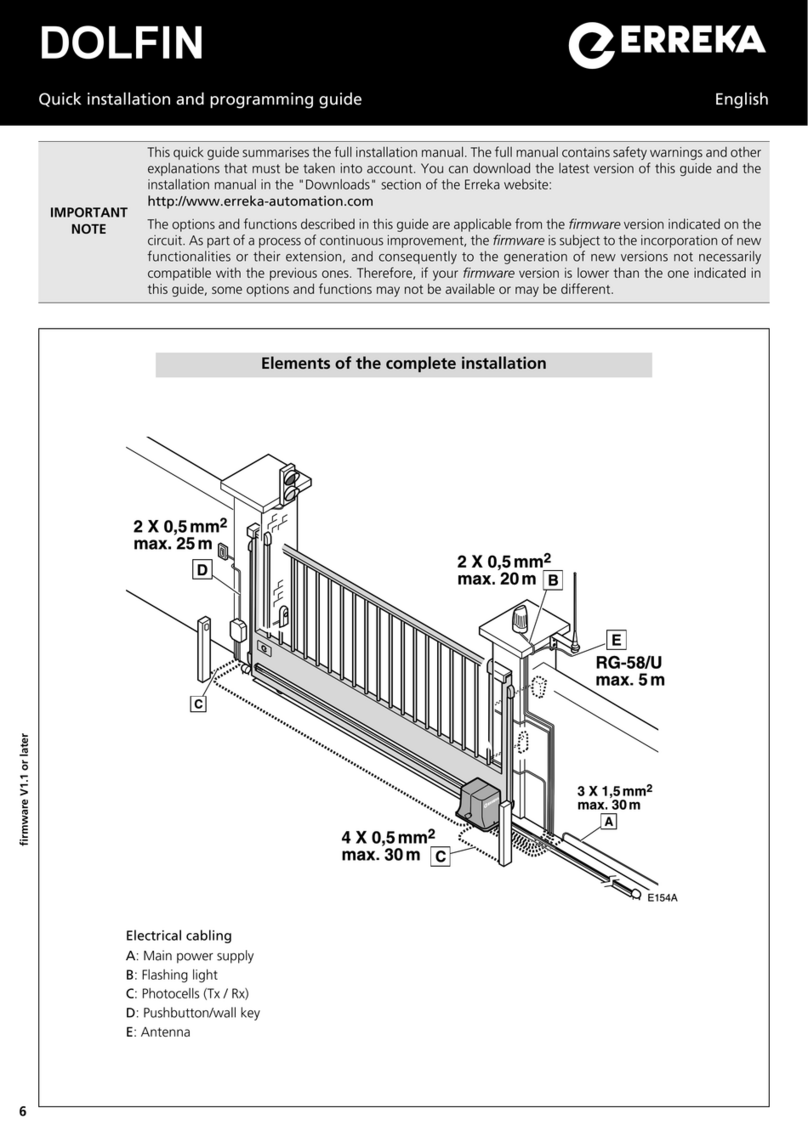
Elements of the complete installation
Electrical cabling
A: Main power supply
B: Flashing light
C: Photocells (Tx/Rx)
D: Pushbutton or key switch
E: Operator (motor + encoder)
F: Antenna
The
TC
closing stopper must be
installed.
The
TA
opening stoppers are only
necessary in outward opening
facilities.
The optional NBULR kit is available for outward opening facilities; this is a special wall bracket which
allows multiple mounting positions, thus making it easier to install the operator.
800
G187B
3,5
Limits on use
G187A
800
We recommend using an electrolock for leaf lengths of over 2.5m.
Values for orientation purposes only. The shape of the leaf and the presence of strong wind may
bring notable differences in the values of the chart.
BL33 (short) BL43 (long)
10
BL33, inward opening (travel: 310mm)
940
310
M187A
100
110
120
130
140
150
160
170
180
190
200
210
110
120
130
140
150
160
170
180
190
200
210
110
120
130
140
150
160
170
180
190
200
210
100
110
120
130
140
150
160
170
180
190
200
210
Example: A = 170mm, B = 140mm, C = 90º
BL43, inward opening (travel: 410mm)
M187B
140
150
160
170
180
190
200
210
220
230
240
250
110
120
130
140
150
160
170
180
190
200
210
260
270
280
290
300
100
220
230
240
250
110
120
130
140
150
160
170
180
190
200
210
100
220
230
240
250
140
150
160
170
180
190
200
210
220
230
240
250
260
270
280
290
300
1140
410
Example: A = 220mm, B = 190mm, C = 90º
BL33, outward opening (travel: 310mm)
M187C
100
110
120
130
140
150
160
170
180
190
200
110
120
130
140
150
160
170
180
190
200
110
120
130
140
150
160
170
180
190
200
100
110
120
130
140
150
160
170
180
190
200
6
3
0
Example: A = 130mm, B = 142mm, C = 110º
BL43, outward opening (travel: 410mm)
M187D
140
150
160
170
180
190
200
210
220
230
240
250
110
120
130
140
150
160
170
180
190
200
210
260
270
280
290
300
100
220
230
240
250
110
120
130
140
150
160
170
180
190
200
210
100
220
230
240
250
140
150
160
170
180
190
200
210
220
230
240
250
260
270
280
290
300
730
Example: A = 220mm, B = 175mm, C = 100º
Levels A and B determine the opening angle C.
Assembly positions and levels
11
D187A
D187B
13
Unlocking
•Insert the key (1) and turn until the cylinder (2)
protrudes a few millimetres.
•Turn the handle (3) 180º, until the cylinder coincides
with the $symbol.
Unlocking for manual operation: Motorised operation locking:
•Turn the handle (1) 180º, until the cylinder coincides
with the %symbol.
•Insert the cylinder (2) by pushing and cover it (3).
13
D187A
A
P187A
B
P187E
1 Mount the wall support.
Levels A and B are measured from the centre of the
hinge to the centre of the bracket orifice.
P187B
P187C P187D
Assembly
2 Mount the operator on the wall support.
3 Position the gate support.
Bear in mind that the operator must be horizontal.
4 Mount the operator on the gate support, adjust the
swivel joint and position the protective cover.
5 Install the opening stopper.
For inward opening: open the
gate manually and install the
operator opening stopper (see
figure).
For outward opening: install
the TA stoppers (see "elements
of the complete installation").
12
P187Z
+24Vdc
CN22
GND
G4 G5
GND
V+
P13
SNG1
P14 P15
SNG2
P16
GND
V+
P17
SNG1
P18 P19
SNG2
P20
ENCODER1 ENCODER2
MOTOR2
MOTOR1
CN13
G6
L mp.
G9 G10
VIVO-D201:
VIVO-D201M:
BATTERY
IN/OUT
CHG
VIVO-D201:
FT
VIVO-D201M:
VIVO-D201:
230Vac, max 2.300W
VIVO-D201M:
125Vac, max 1.250W
F2
ST1
FT1
P1 P2 P3
ST2
FT2
P4 P5 P6
STOP
P7 P8
WARNING
LIGHT
P9
P10
24V
P11
P12
LOCK
G7 G8
Courtesy
Light
NL
POWER
+
P21 P22 P23
F3
F1 LB/ LR
P24 P25
EDGE
-FT
(Test)
AUX
24 Vdc
SW1
V
GND SNG1
G1 G2
GND
G3
A1 Operator 1
A2 Operator 2
G1/G4 Red cable (motor)
G2/G5 Blue cable (motor)
V+ Brown cable (encoder supply)
GND Mesh (encoder mass)
SNG1 Green cable (encoder signal 1)
SW1 Main switch
•Select the number of operators using C0 (C001: one operator, C002: two operators).
•Programme C7 for operation with encoder (C701).
•For the BUL operator, programme C301.
Electrical connections VIVO-D201(M)
Turning direction check: after connecting the power and activating any of the key devices, the
gate makes a reset (the display showsrS): the gate closes until it reaches the stopper, assigning this
stopper with the position "gate closed" If it opens instead of closes during reset, change the turning
direction (C101 or C102 for A1 and C201 or C202 for A2).