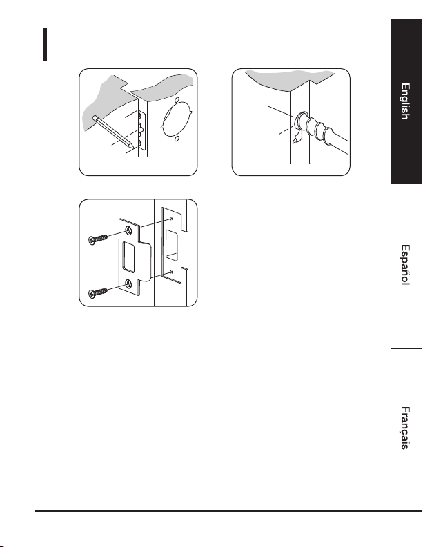
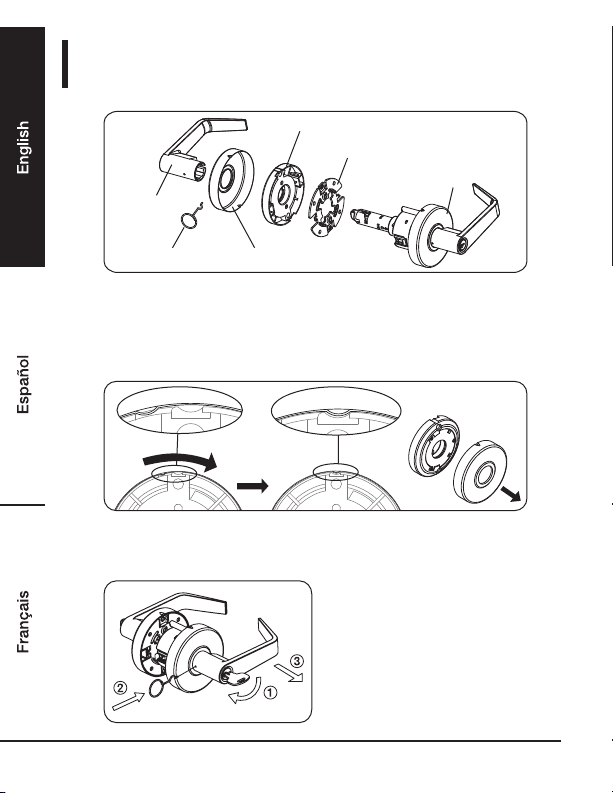
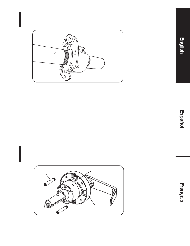
AMAZON COMMERCIAL Entry B07RV879LT Operating and safety instructions

Door Lever
Palanca de Puerta
Levier de Porte

Entry
B07RV879LT, B07RRZYP9Y, B07RQWX6FQ
B07RV874SL
Privacy
B07RWR52V6, B07RV874T6, B07RV874TN
B07RQWVS84
Passage
B07RQWVTXW, B07RRZYS3M, B07RWR52WN
B07RV872KN
English ..................................... 03
Español .................................... 14
Français ................................... 25

3
Contents:
Before getting started, ensure the package contains the
following components:
Welcome Guide •English
Entry
• One (1) Lock Body
One (1) Strike Plate•
One (1) Latch•
Two (2) Keys•
Two (2) Phillips head wood screws for latch plate•
Two (2) Phillips head wood screws for strike plate•
Two (2) Phillips head machine screws for attaching lock body
•
Privacy
• One (1) Lock Body
One (1) Strike Plate•
One (1) Latch•
One (1) Safety Key•
Two (2) Phillips head wood screws for latch plate•
Two (2) Phillips head wood screws for strike plate•
Two (2) Phillips head machine screws for attaching lock body
•
Passage
• One (1) Lock Body
One (1) Strike Plate•
One (1) Latch•
Two (2) Phillips head wood screws for latch plate•
Two (2) Phillips head wood screws for strike plate•
Two (2) Phillips head machine screws for attaching lock body•

4
IMPORTANT SAFEGUARDS
Read these instructions carefully and retain them for
future use. If this product is passed to a third party,
then these instructions must be included.
Before First Use
•Check for transport damage.
Risk of suffocation! Keep any packaging
materials away from children – these
materials are a potential source of danger,
e.g. suffocation.
DANGER
Recommended Tools:
• 1" (25 mm) Wood Drill Bit
• 2-1/18" (54 mm) Hole Saw
• 5/16" (8 mm) Drill Bit
• Level
• Phillips Screwdriver
• Hammer
• Pencil
• Tape Measure
• Safety Glasses
• Tape
• Wood Chisel

Step 1:
MARK DOOR
Step 2:
DRILLING HOLES
• Fold the template at the dotted line and tape the template
onto the interior side of the door.
Mark hole for the location for the lever and latch.
38" (965 mm) from floor
recommended height
•
Drill a 2-1/18" (54 mm) holes through door face as marked.
Drill a 1" (25 mm) hole as marked for the latch.
OPTION 1: Drill two (2) 5/16" (8mm) holes for screw post.
5/16"(8mm)
HOLE FOR
SCREW POST
Option 1:
1" OR 31/32"
(24.6mm OR
25.4mm) HOLE
FOR LATCH
2-1/8"(54mm)
HOLE FOR
LOCKSET
NOTE: DRILL THE 2-1/8” (54mm) HOLE FROM BOTH
SIDES TO AVOID SPLITTING WOOD.
A
B
C
•
•
5

Step 3:
INSTALL LATCH
•Insert latch in hole keeping it parallel to face of door.
Outline face plate with pencil and remove latch.
Chisel 1/8" (3 mm) deep or until latch face is flush with
door edge.
Insert latch and tighten screws.
Make sure the latch is inserted with the word
"TOP" facing upward.
LATCHBOLT BEVEL MUST BE FACING THE
SAME WAY THE DOOR CLOSES.
•
•
•
A B
C D
NOTICE
NOTICE
6

Step 4:
INSTALL STRIKER PLATE
•Close door to mark horizontal center line of strike.
•Chisel out door jamb 3/32" (2.4mm) deep or until strike
plate sits flush with door jamb. Tighten screws securely.
•Measure one half of door thickness from door stop to mark
vertical center line of strike. Drill 1"(25.4mm) hole, 1/2"
(12.7mm) deep at intersection of horizontal and vertical
center lines.
CENTER
LINE
1"(25.4mm)
HOLE
1/2"(12.7mm)
DEEP
DOOR
STOP
A B
C
7

8
Step 5:
• Insert tip of the lever removing tool into the hole on the
bottom of lever.
• Push down on the lever catch pin and slide off inside lever,
rose, rose liner and mounting plate.
INSIDE LEVER
INSIDE ROSE
INSIDE ROSE LINER
INSIDE MOUNTING PLATE
LEVER CATCH TOOL
OUTSIDE LEVER ASSEMBLY
1. Remove the Inside rose,inside liner and trim
• Remove the rose liner by turning it clockwise and aligning the
the bump on the rose to the recess on the rose liner.
• Insert the key into the cylinder
and turn 45 degree and hold.
• Push down on the lever catch
pin and slide off outside lever
and rose.

9
Step 6:
ADJUST FOR DOOR THICKNESS
• Adjust the mounting plate to the door thickness by turning
it clockwise or counter-clockwise.
Step 7:
INSTALL REMOVABLE THRU-BOLT (SCREW POST)
OUTSIDE
MOUNTING PLATE
THRU-BOLT
OUTSIDE ROSE

10
Re-assemble the outside lever and rose
A. Keep the thru-bolt on lock body if you chose "C." on
step1. Make clearance between outside mounting plate
and insert the removable thru-bolt (screw post) into the
cavities of outside mounting plate.
Continuing the follow up instructions.
B. Remove the thru-bolt if you chose "Option 1"
on step 1. Continuing the follow up instructions.
Step 8:
INSTSTALL OUTSIDE LEVER ASSEMBLY
• Install outside lever assembly on thedoor. Make suretail
of latch engaging with retractor correctly as illustration left.
LOCK
BODY
ASSEMBLY
LATCH OUTSIDE LEVER
ASSEMBLY

11
Step 9:
INSTALL INSIDE MOUNTING PLATE AND ROSE LINER
Option 1: WITH THRU-BOLT
Place mounting plate and rose liner on door face and turn
up the lever slightly and tighten with two mounting screws.
Option 2: WITHOUT THRU-BOLT
Place mounting plate on door face and turn up the lever
slightly and tighten with two mounting screws.
Place rose liner onmounting plate and tighten with a
retainingscrew.
MOUNTING SCREW
INSIDE ROSE LINER
INSIDE MOUNTING PLATE
MOUNTING SCREW
INSIDE MOUNTING PLATE
RETAINING SCREW
INSIDE ROSE
LINER

12
Cleaning and Maintenance
Cleaning
• To clean, wipe with a soft, slightly moist cloth.
• Never use corrosive detergents, wire brushes, abrasive
scourers, metal or sharp utensils to clean the product.
Maintenance
• Check the components regularly to make sure all screws
and bolts are tightened.
• Store in a cool and dry place away from children and
pets, ideally in original packaging.
• Avoid any vibrations and shocks.
• A. Press rose ontorose liner. Be sureto fit rose in recess
of rose liner.
• B. Use lever catch to press down catch in thehole and
push inside lever all the way in until clicks into catch
hole.
INSIDE
ROSE LINER
INSIDE ROSE INSIDE LEVER INSIDE ROSE
A B
Step 10:
INSTALL INSIDE ROSE AND LEVER

13
Warranty Information
To obtain a copy of the warranty for this product:
US: Visit amazon.com/AmazonCommercial/Warranty
US: +1-866-216-1072
Feedback and Help
Love it? Hate it? Let us know with a customer review.
AmazonBasics is committed to delivering customer-driven
products that live up to your high standards. We encourage you
to write a review sharing your experiences with the product.
US: amazon.com/review/review-your-purchases#
US: amazon.com/gp/help/customer/contact-us
The Lever Removing Tool /
Privacy Lever Safety Key
• The lever removing tool is used when removing
the lever(s) from the knob assembly.
• Included in this kit is an emergency safety key that can be used
to unlock the door lever in the event it becomes locked from
the inside.
• Insert the safety key into the slot and turn the key counter-
clockwise to inlock the door lever.

Contenido:
Antes de empezar, asegúrese de que el paquete contenga
los siguientes componentes:
Guía de Bienvenida • Español
Entrada
• Un (1) cuerpo de cerradura
• Un (1) seguro
• Una (1) placa de impacto
• Dos (2) llaves
• Dos (2) tornillos de madera con cabeza Phillips para la placa del seguro
• Dos (2) tornillos de madera con cabeza Phillips para la placa de impacto
• Dos (2) tornillos para maquinaria con cabeza Phillips para fijar el cuerpo de la cerradura
Privacidad
• Un (1) cuerpo de cerradura
• Un (1) seguro
• Una (1) placa de impacto
• Una (1) llave de privacidad
• Dos (2) tornillos de madera con cabeza Phillips para la placa del seguro
• Dos (2) tornillos de madera con cabeza Phillips para la placa de impacto
• Dos (2) tornillos para maquinaria con cabeza Phillips para fijar el cuerpo de la cerradura
Paso
• Un (1) cuerpo de cerradura
• Un (1) seguro
• Una (1) placa de impacto
• Dos (2) tornillos de madera con cabeza Phillips para la placa del seguro
• Dos (2) tornillos de madera con cabeza Phillips para la placa de impacto
• Dos (2) tornillos para maquinaria con cabeza Phillips para fijar el cuerpo de la cerradura
14

PRECAUCIONES IMPORTANTES
Lea atentamente estas instrucciones y guárdelas
para usarlas más adelante. En caso de entregar
este producto a un tercero, también se deben
incluir estas instrucciones.
Antes de usar por primera vez
• Revise por si hay daños ocurridos en el transporte.
¡Riesgo de asfixia! Mantenga los materiales
de empaque lejos de los niños, ya que estos
materiales son una posible fuente de peligro,
por ejemplo, asfixia.
PELIGRO
Herramientas recomendadas:
• Broca para perforar madera de 1 pulgada (25 mm)
• Sierra copa de 2-1/18 pulgadas (54 mm)
• Broca de 5/16 pulgadas (8 mm)
• Nivel
• Destornillador Phillips
• Martillo
• Lápiz
• Cinta de medir
• Antiparras de seguridad
• Cinta
• Cincel para madera
15

16
Paso 1 :
MARQUE LA PUERTA
Paso 2 :
PERFORACIÓN DE LOS ORIFICIOS
Perfore orificios de 2-1/18 pulgadas (54 mm) en la puerta
siguiendo las marcas.
Perfore un orificio de 1 pulgada (25 mm) siguiendo las
marcas para el seguro.
OPCIÓN 1: Perfore dos (2) orificios de 5/16 pulgadas (8 mm)
para el soporte del tornillo.
ORIFICIO DE
5/16 pulgadas
(8 mm) PARA EL
SOPORTE DEL
TORNILLO
Opción 1:
ORIFICIO DE 1
pulgada O 31/32
pulgada (24,6 mm
O 25,4 mm) PARA
EL SEGURO
2-1/8 pulgadas
(54 mm) ORIFICIO
PARA LA
CERRADURA
NOTA: PERFORE EL ORIFICIO DE 2-1/8 pulgadas (54 mm)
DESDE AMBOS LADOS PARA EVITAR DIVIDIR LA
MADERA.
•
•
• Pliegue la plantilla en la línea punteada y péguela con cinta
en el costado interior de la puerta.
Marque el orificio de la ubicación de la palanca y seguro.
38 pulgadas (965 mm)
desde la altura
recomendada del piso
•
A
B
C

Paso 3 :
INSTALACIÓN DEL SEGURO
Inserte el seguro en el orificio manteniéndolo paralelo a la
cara de la puerta.
Marque la placa frontal usando un lápiz y saque el seguro.
Cincele 1/8 pulgadas (3 mm) de profundidad o hasta que la
cara del seguro quede al ras con el borde de la puerta.
Inserte el seguro y apriete los tornillos.
Asegúrese de que el seguro quede insertado
con la palabra “TOP” hacia arriba.
EL BISEL DEL PERNO DEL SEGURO DEBE
QUEDAR DE FRENTE HACIA DONDE CIERRA
LA PUERTA.
•
•
•
•
A B
C D
AVISO
AVISO
17

Paso 4 :
INSTALACIÓN DE LA PLACA DE IMPACTO
•Cierre la puerta para marcar la línea central de impacto
horizontal.
•Mida la mitad del grosor de la puerta desde el tope de la
puerta para marcar la línea central de impacto. Perfore un
orificio de 1 pulgada (25,4 mm), 1/2 pulgadas (12,7 mm) de
profundidad en la intersección de la línea central vertical y
horizontal.
•Cincele 3/32 pulgadas (2,4 mm) de profundidad en el
soporte vertical del marco de la puerta o hasta que la placa
de impacto quede pareja con el marco de la puerta. Apriete
los tornillos firmemente.
LÍNEA
CENTRAL
1 pulgada
(25,4 mm)
PERFORE
1/2 pulgadas
(12,7 mm)
DE
PROFUNDIDAD
PUERTA
TOPE
A B
C
18

19
Paso 5 :
•Inserte la punta de la herramienta para sacar la palanca en
el orificio de la parte inferior de la palanca.
•Presione sobre el pasador de cierre de la palanca y deslice
hacia afuera la palanca, rosa interior y placa de montaje.
PALANCA
INTERIOR
ROSA INTERIOR
RECUBRIMIENTO DE LA ROSA INTERIOR
PLACA DE MONTAJE INTERIOR
HERRAMIENTA DE
CIERRE DE LA PALANCA
PALANCA EXTERIOR
1. Saque la rosa interior, el recubrimiento inferior y el borde
•Saque el recubrimiento de la rosa girando hacia la izquierda
y alineando el tope de la rosa con el hueco del recubrimiento
de la rosa.
•Inserte la llave en el cilindro,
gírela en 45 grados y
sosténgala.
•Presione sobre el pasador
de cierre de la palanca y
deslice hacia afuera la
palanca exterior y la rosa.

20
Paso 6 :
AJUSTE DEL GROSOR DE LA PUERTA
• Ajuste la placa de montaje según el grosor de la puerta,
girando hacia la izquierda o hacia la derecha.
Paso 7 :
INSTALE EL PERNO PASANTE EXTRAIBLE
(SOPORTE DEL TORNILLO)
PLACA DE
MONTAJE
EXTERIOR
PERNO PASANTE
ROSA EXTERIOR
This manual suits for next models
11
Table of contents
Languages:
Other AMAZON COMMERCIAL Door Opening System manuals