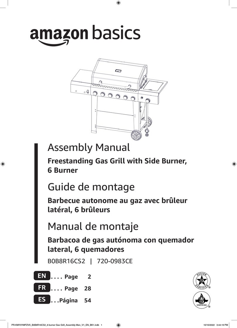
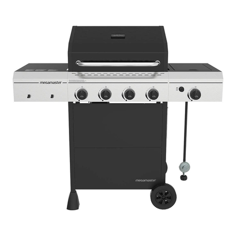
AmazonBasics B0B8QV3MS2 User manual

Assembly Manual
Freestanding Gas Grill with Side Burner,
4 Burner
Guide de montage
Barbecue autonome au gaz avec brûleur
latéral, 4 brûleurs
Manual de montaje
Barbacoa de gas autónoma con quemador
lateral, 4 quemadores
B0B8QV3MS2 | 720-0804HE
EN .... Page 2
FR .... Page 28
ES ...Página 55
PR-KMY0YMPZVX_B0B8QV3MS2_4 burner Gas Grill_Assembly Man_V1_BK1.indb 1PR-KMY0YMPZVX_B0B8QV3MS2_4 burner Gas Grill_Assembly Man_V1_BK1.indb 1 10/7/2022 12:16:40 PM10/7/2022 12:16:40 PM
FINAL V1

EN
2
Package Contents..................................................................................................................................................................................................... 3
Assembling the Grill................................................................................................................................................................................................. 7
Feedback and Help.................................................................................................................................................................................................27
Contents
PR-KMY0YMPZVX_B0B8QV3MS2_4 burner Gas Grill_Assembly Man_V1_BK1.indb 2PR-KMY0YMPZVX_B0B8QV3MS2_4 burner Gas Grill_Assembly Man_V1_BK1.indb 2 10/7/2022 12:16:40 PM10/7/2022 12:16:40 PM

EN
3
Package Contents
Parts
Part Name Image Quantity
1 Front left leg 1
2 Back left leg 1
3Bottom left frame
support 1
4 Front right leg 1
5 Back right leg 1
6Bottom right frame
support 1
7 Back frame support 1
8 Top left frame support 1
9 Top right frame support 1
10 Front panels 2
PR-KMY0YMPZVX_B0B8QV3MS2_4 burner Gas Grill_Assembly Man_V1_BK1.indb 3PR-KMY0YMPZVX_B0B8QV3MS2_4 burner Gas Grill_Assembly Man_V1_BK1.indb 3 10/7/2022 12:16:41 PM10/7/2022 12:16:41 PM

EN
4
Part Name Image Quantity
11 Feet 2
12 Tank exclusion bar 1
13 Tank holder bar 1
14 Grill box 1
15 Left side shelf 1
16 Shelf brackets 2
17 Left shelf cover 1
18 Right sideburner shelf 1
19 Right shelf cover 1
20 Side burner 1
21 Grease tray 1
PR-KMY0YMPZVX_B0B8QV3MS2_4 burner Gas Grill_Assembly Man_V1_BK1.indb 4PR-KMY0YMPZVX_B0B8QV3MS2_4 burner Gas Grill_Assembly Man_V1_BK1.indb 4 10/7/2022 12:16:42 PM10/7/2022 12:16:42 PM

EN
5
Part Name Image Quantity
22 Grease pan holder 1
23 Grease pan 1
24 AA battery 1
25 Sideburner control knob 1
26 Heat plates 4
27 Cooking grates 2
28 Wheels 2
29 Warming rack 1
30 Side burner grate 1
PR-KMY0YMPZVX_B0B8QV3MS2_4 burner Gas Grill_Assembly Man_V1_BK1.indb 5PR-KMY0YMPZVX_B0B8QV3MS2_4 burner Gas Grill_Assembly Man_V1_BK1.indb 5 10/7/2022 12:16:43 PM10/7/2022 12:16:43 PM

EN
6
Hardware
Part Name Image Quantity
A1/4-20x1/2” truss head
screws 18
B5/32-32x2/5” truss
head screws 15
C1/4” at washers 6
D5/16” at washers 2
E 5/16” nuts 2
F5/32” at washer 2
Tools Needed
Philips screwdriver Adjustable wrench
PR-KMY0YMPZVX_B0B8QV3MS2_4 burner Gas Grill_Assembly Man_V1_BK1.indb 6PR-KMY0YMPZVX_B0B8QV3MS2_4 burner Gas Grill_Assembly Man_V1_BK1.indb 6 10/7/2022 12:16:43 PM10/7/2022 12:16:43 PM

EN
7
Assembling the Grill
Step 1
1. Loosen the eight pre-installed screws on the front left leg (1), back left leg (2), front right leg (4), and back right leg (5).
2. Slide the keyhole slots in the bottom left frame support (3) onto the screws in the front left leg (1) and back left leg (2),
then retighten the four screws.
3. Slide the keyhole slots in the bottom right frame support (6) onto the screws in the front right leg (4) and back right leg (5),
then retighten the four screws.
Step 2
1. Loosen the four pre-installed screws on the left leg assembly and right leg assembly.
2. Connect the left leg assemby to the right leg assembly by sliding the keyhole slots in the back frame support (7) onto the
screws you loosened. Make sure the screw holes along the edge of the back frame support are facing upward, then tighten
the four screws.
PR-KMY0YMPZVX_B0B8QV3MS2_4 burner Gas Grill_Assembly Man_V1_BK1.indb 7PR-KMY0YMPZVX_B0B8QV3MS2_4 burner Gas Grill_Assembly Man_V1_BK1.indb 7 10/7/2022 12:16:44 PM10/7/2022 12:16:44 PM

EN
8
Step 3
1/4-20x1/2” truss head screws (x8)
1. Secure the top left frame support (8) to the left legs with four 1/4-20x1/2” truss head screws (A).
2. Secure the top right frame support (9) to the right legs with four 1/4-20x1/2” truss head screws (A).
NOTICE The top screw hole in each frame support will stay open.
PR-KMY0YMPZVX_B0B8QV3MS2_4 burner Gas Grill_Assembly Man_V1_BK1.indb 8PR-KMY0YMPZVX_B0B8QV3MS2_4 burner Gas Grill_Assembly Man_V1_BK1.indb 8 10/7/2022 12:16:44 PM10/7/2022 12:16:44 PM

EN
9
Step 4
1. Loosen the eight pre-installed screws on the left front leg (1) and right front leg (4).
2. Slide the two front panels (10) onto the screws on the front supports, then retighten the eight screws.
PR-KMY0YMPZVX_B0B8QV3MS2_4 burner Gas Grill_Assembly Man_V1_BK1.indb 9PR-KMY0YMPZVX_B0B8QV3MS2_4 burner Gas Grill_Assembly Man_V1_BK1.indb 9 10/7/2022 12:16:44 PM10/7/2022 12:16:44 PM

EN
10
Step 5
5/16” at washers (x2) 5/16” nuts (x2)
Slide the wheels (28) onto the bottom of the right legs, insert a 5/16” at washer (D) onto each end, then secure each wheel
with a 5/16” nut (E). Tighten each nut with a wrench.
PR-KMY0YMPZVX_B0B8QV3MS2_4 burner Gas Grill_Assembly Man_V1_BK1.indb 10PR-KMY0YMPZVX_B0B8QV3MS2_4 burner Gas Grill_Assembly Man_V1_BK1.indb 10 10/7/2022 12:16:44 PM10/7/2022 12:16:44 PM

EN
11
Step 6
Push the feet (11) onto the bottom of the left legs. The feet should point outward toward the front and back of the grill.
PR-KMY0YMPZVX_B0B8QV3MS2_4 burner Gas Grill_Assembly Man_V1_BK1.indb 11PR-KMY0YMPZVX_B0B8QV3MS2_4 burner Gas Grill_Assembly Man_V1_BK1.indb 11 10/7/2022 12:16:44 PM10/7/2022 12:16:44 PM

EN
12
Step 7
5/32-32x2/5” truss head screw (x1)
1. Insert the end of the tank exclusion bar (12) into the hole on the top edge of the front panel.
2. Align the other end of the tank exclusion bar with the hole in the back frame support, then secure with a 5/32-32x2/5”
truss head screw (B).
Step 8
Insert the ends of the tank holder bar (13) into the holes on the inside of the right legs.
PR-KMY0YMPZVX_B0B8QV3MS2_4 burner Gas Grill_Assembly Man_V1_BK1.indb 12PR-KMY0YMPZVX_B0B8QV3MS2_4 burner Gas Grill_Assembly Man_V1_BK1.indb 12 10/7/2022 12:16:44 PM10/7/2022 12:16:44 PM
EN
13
Step 9
Remove the two screws at the front corners of the grill box (14). These screws secured the control panel during transport and
won’t be used again.
Step 10
With a partner, lift the grill box (14) onto the supports.
PR-KMY0YMPZVX_B0B8QV3MS2_4 burner Gas Grill_Assembly Man_V1_BK1.indb 13PR-KMY0YMPZVX_B0B8QV3MS2_4 burner Gas Grill_Assembly Man_V1_BK1.indb 13 10/7/2022 12:16:45 PM10/7/2022 12:16:45 PM

EN
14
Step 11
1/4-20x1/2” truss head screws (x4)
Make sure that the grill box is fully seated, then secure the grill box (14) with four 1/4-20x1/2” truss head screws (A).
PR-KMY0YMPZVX_B0B8QV3MS2_4 burner Gas Grill_Assembly Man_V1_BK1.indb 14PR-KMY0YMPZVX_B0B8QV3MS2_4 burner Gas Grill_Assembly Man_V1_BK1.indb 14 10/7/2022 12:16:45 PM10/7/2022 12:16:45 PM

EN
15
Step 12
5/32-32x2/5” truss head screws (x4)
1. Align a shelf bracket (16) with the left side shelf (15) and left shelf cover (17), then secure with two 5/32-32x2/5” truss
head screws (B). Do not fully tighten.
2. Secure the edge of the left side shelf (15) and left shelf cover (17) with two more 5/32-32x2/5” truss head screws (B).
3. Fully tighten the screws.
Step 13
Loosen the two upper screws on the left side of the grill box, then slide the left shelf assembly onto the grill box. The grill box
screws should t into the shelf’s keyhole slots.
LEFT SIDE
PR-KMY0YMPZVX_B0B8QV3MS2_4 burner Gas Grill_Assembly Man_V1_BK1.indb 15PR-KMY0YMPZVX_B0B8QV3MS2_4 burner Gas Grill_Assembly Man_V1_BK1.indb 15 10/7/2022 12:16:45 PM10/7/2022 12:16:45 PM

EN
16
Step 14
1/4-20x1/2” truss head screws (x3) 1/4” at washers (x3)
Secure the left shelf assembly with three 1/4” at washers (C) and three 1/4-20x1/2” truss head screws (A).
PR-KMY0YMPZVX_B0B8QV3MS2_4 burner Gas Grill_Assembly Man_V1_BK1.indb 16PR-KMY0YMPZVX_B0B8QV3MS2_4 burner Gas Grill_Assembly Man_V1_BK1.indb 16 10/7/2022 12:16:45 PM10/7/2022 12:16:45 PM

EN
17
Step 15
5/32-32x2/5” truss head screws (x2)
1. Make sure that the shelf assembly is fully seated in the keyhole slot, then retighten the screws you loosened in “Step 13” on
page 15.
2. Secure the left shelf cover with two 5/32-32x2/5” truss head screws (B).
PR-KMY0YMPZVX_B0B8QV3MS2_4 burner Gas Grill_Assembly Man_V1_BK1.indb 17PR-KMY0YMPZVX_B0B8QV3MS2_4 burner Gas Grill_Assembly Man_V1_BK1.indb 17 10/7/2022 12:16:46 PM10/7/2022 12:16:46 PM

EN
18
Step 16
5/32-32x2/5” truss head screws (x4)
1. Align a shelf bracket (16) with the right sideburner shelf (18) and right shelf cover (19), then secure with two 5/32-32x2/5”
truss head screws (B). Do not fully tighten.
2. Secure the edge of the right sideburner shelf (18) and right shelf cover (19) with two more 5/32-32x2/5” truss head screws
(B).
3. Fully tighten the screws.
PR-KMY0YMPZVX_B0B8QV3MS2_4 burner Gas Grill_Assembly Man_V1_BK1.indb 18PR-KMY0YMPZVX_B0B8QV3MS2_4 burner Gas Grill_Assembly Man_V1_BK1.indb 18 10/7/2022 12:16:46 PM10/7/2022 12:16:46 PM

EN
19
Step 17
Loosen the two upper screws on the right side of the grill box, then slide the right sideburner assembly (18) onto the grill box.
The grill box screws should t into the shelf’s keyhole slots.
Step 18
1/4-20x1/2” truss head screws (x3) 1/4” at washers (x3)
Secure the right sideburner assembly (18) with three 1/4” at washers (C) and three 1/4-20x1/2” truss head screws (A).
PR-KMY0YMPZVX_B0B8QV3MS2_4 burner Gas Grill_Assembly Man_V1_BK1.indb 19PR-KMY0YMPZVX_B0B8QV3MS2_4 burner Gas Grill_Assembly Man_V1_BK1.indb 19 10/7/2022 12:16:46 PM10/7/2022 12:16:46 PM

EN
20
Step 19
5/32-32x2/5” truss head screws (x2)
1. Make sure that the sideburner assembly is fully seated in the keyhole slot, then retighten the screws you loosened in “Step
17” on page 19.
2. Secure the right shelf cover with two 5/32-32x2/5” truss head screws (B).
Step 20
1. Loosen the two sideburner control screws. Do not remove the screws.
2. Place the sideburner valve into the hole of the right sideburner shelf cover, then slide it down to lock in place.
3. Retighten the two sideburner control screws.
PR-KMY0YMPZVX_B0B8QV3MS2_4 burner Gas Grill_Assembly Man_V1_BK1.indb 20PR-KMY0YMPZVX_B0B8QV3MS2_4 burner Gas Grill_Assembly Man_V1_BK1.indb 20 10/7/2022 12:16:47 PM10/7/2022 12:16:47 PM
Other manuals for B0B8QV3MS2
1
This manual suits for next models
1
Table of contents
Languages:
Other AmazonBasics Grill manuals