AMBIC Classic User manual

Fig.1
Part No. AV/2000
INSTRUCTIONS
CLASSIC TEAT SPRAY SYSTEM
I
H
C
F
G
KJ
B
D
A
E

FIG. 3
1. SCHEMATIC LAYOUT
2. INSTALLATION
FIG. 2
FIG. 5
FIG. 6
10 mm Ø
3/8” Ø
ATS/2006
ATS/426
ATS/436
ATS/401
1
ATS/425
C E F
FIG. 4

3. MAINTENANCE
FIG. 7
FIG. 9
FIG. 10
ATS/425
ATS/2006
ATS/435
ATS/446
ATS/445
ATS/447
ATS/448
ATS/444(1)
ATS/442(1)
ATS/443(1)
FIG. 8
2
X
ATS/456

4. OPERATION
FIG. 11 FIG. 12
FIG. 13
3
FIG. 14
REF NO QTY DESCRIPTION
AATS/401 1 Power Unit
3 Screws & Plugs
BATS/413 1 Vacuum Pipe Adaptor
C/D ATS/412 1 Liquid Intake Pipe + Filter
E/F 1 18M Transparent Tubing
GATS/407 3 T. Connectors
REF NO QTY DESCRIPTION
HATS/402
ATS/502 3 Spray Guns
IATS/406 3 Retractable Coil
JATS/429 2 Blanking Plugs
KATS/411 30 Cable Ties
5. PARTS LIST (refer to FIG. 1)

The Classic Teat Spray System is designed exclusively for use in
milking installations. Any application outside the use described
in this operating manual will be taken to be not in accordance
with the intended purpose. The manufacturer/supplier will not
be held responsible for any losses arising as a result of such use.
The user will take full responsibility for use. USE IN
ACCORDANCE WITH THE INTENDED PURPOSE ALSO
INCLUDES COMPLYING WITH THE OPERATING MANUAL AND
THE CONDITIONS FOR INSPECTION AND MAINTENANCE.
A
AT
TT
TE
EN
NT
TI
IO
ON
N!
!Whilst in operation the installation is under an
operating pressure of 3 to 4 bar!
Do not spray dip into your eyes! If you do, rinse with copious
amounts of water and seek medical attention!
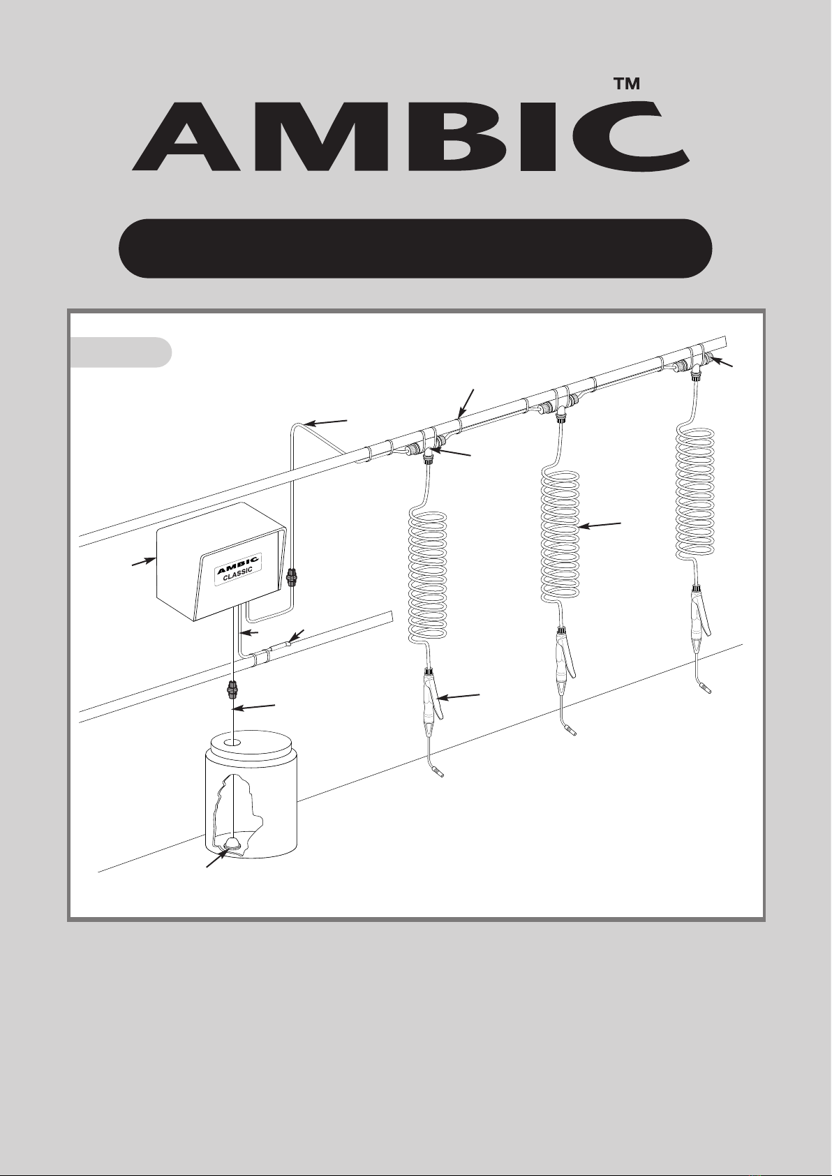
For general parlour layout refer to Fig. 1.
Position Power Unit (A) not more than 2 metres (6ft) above the
base of the Chemical Container, preferably in a dust free
environment, close to a regulated Vacuum Line.
Screw white bracket to wall securely using 3 x screws and wall
plugs supplied. Attach the Power Unit (A) ensuring that the
hooks properly engage the rectangular holes in the back plate.
V
VA
AC
CU
UU
UM
MS
SU
UP
PP
PL
LY
YDrill a 10mm Ø (3/8”Ø) hole in the top of
a regulated main vacuum line (FIG. 3). Remove burrs, lubricate
Pipe Adapter (B) and twist into hole.
Secure Tube (E) with Cable Ties (K). Do not over-tighten and
avoid sharp bends. Cut tube to correct length or leave loosely
coiled.
C
CH
HE
EM
MI
IC
CA
AL
LI
IN
NT
TA
AK
KE
ERemove the nut and end of line plug
from the straight connector on the liquid intake tubing
(FIG. 2 C). Place container of chemical in position and insert
tube fitted with the filter so that the filter (D) rests on the
bottom of the Chemical Container.
Insert tube through nut, warm end of tube to ease assembly
and push fully onto inlet straight connector (Fig2 C). Tighten
nut firmly with fingers. Do not use pliers or other tools. This
method (FIG. 5) should be used when connecting all such
fittings on Classic.
P
PR
RE
ES
SS
SU
UR
RE
EL
LI
IN
NE
ERemove the end of line plug from the straight
connector (FIG. 2 F) on the pressure line and attach one end of
the coil of transparent tubing. Retain plug to seal last ‘T’
connector. Determine position of ‘T’s (G) and strap loosely to a
suitable support (FIG. 4). Cut suitable lengths of Tubing (F)
strapping and connecting to ‘T’s (G) and outlet straight
connector. Attach Coils (I) and Guns (H) (FIG. 6). Seal open
end of last ‘T’ with Blanking Plug (J) and Nut.
Finally, once positions are correct, fully tighten Cable Ties. Do
not over-tighten on tubing and avoid sharp bends.
When installation is complete, turn on Vacuum Pump. Power
Unit will automatically start, reaching full pressure within 1
minute.
There will be some air in the system. To expend this, hold each
gun vertically above the Delivery Line at arms length pointing
away from face. Press gun lever until air bubbles are no longer
apparent.
Classic is suitable for use with any recognised Teat Disinfectant
Spray except Sodium Hypochlorite and Peroxyacetic Acid.
When using concentrates, ensure that the manufacturers
instructions are followed. Agitation may, periodically, be
required.
Important: Replenish disinfectant supply before it runs out to
prevent air entering the system.
S
SP
PR
RA
AY
YI
IN
NG
GFor effective Mastitis Pathogen control the teats
must be completely covered with disinfectant. On adjustable
nozzle guns rotate nozzle to achieve correct spray pattern
(FIG. 11). Fixed cone nozzles (as on AJS/502) do not require
adjustment.
The nozzle should ideally be positioned approximately 15cm
(6”) below the teats. Optimum and economical coverage is
achieved by employing a circular movement (FIG. 12 & 13).
Application time will differ between cows; however, on average
should be approximately 1 second per cow.
E
EN
ND
DO
OF
FM
MI
IL
LK
KI
IN
NG
Gwhen the main Vacuum Supply is turned off,
the Power Unit automatically returns pressurised disinfectant to
the Chemical Container. This ensures immediate safety and
also flushes any debris from the Intake Filter (D).
W
Wo
or
rk
ki
in
ng
go
on
nt
th
he
eP
Po
ow
we
er
rU
Un
ni
it
tTurn off and disconnect vacuum
supply and ensure that unit is depressurized BEFORE
disconnecting any tubing, by opening/disconnecting one or
more guns. Remove the Power Unit to a safe and convenient
working surface. Remove the case by undoing the four
retaining screws.
D
DI
IR
RE
EC
CT
TI
IO
ON
NA
AL
LV
VA
AL
LV
VE
EA
AT
TS
S/
/4
42
25
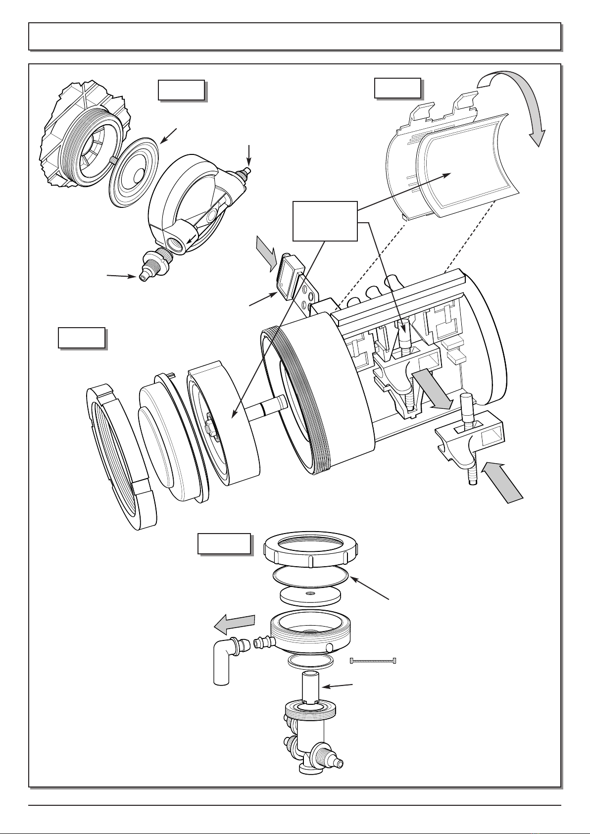
5The Directional Valve (FIG. 2
ATS/425) is mounted at the top right hand side of the Power
Unit: this directs vacuum to the Diaphragm Pump. Spare parts
are contained in Service Kit ATS/448.
Complete Replacement
Unscrew the two retaining screws from the back plate and
carefully remove the three vacuum tubes. Warming and noting
their order will assist removal and fitting. Refitting is a reversal
of removal.
V
VA
AL
LV
VE
EF
FI
IL
LT
TE
ER
R(ATS/444) Replace every 1000 hours or sooner
if heavily contaminated. Manually release Filter Cover Clips by
levering with fingers (FIG. 8). Carefully remove Filter taking
care not to drop dust into the working parts. Fit new Filter by
reversing the process.
B
BL
LE
EE
ED
DI
IN
NS
SE
ER
RT
TA
AT
TS
S/
/4
44
47
7Pull out of main body taking care not
to dislodge the 4 ‘O’ Rings. Inspect two small holes near the
end (FIG. 9) and clean every 1000 hours, or sooner if heavily
contaminated, using strand of wire attached to bleed insert.
D
DI
IA
AP
PH
HR
RA
AG
GM
MA
AS
SS
SE
EM
MB
BL
LY
Y(ATS/443) Replace, using ATS/448,
every 3000 hours. First remove Valve Filter (see above). Pull
Drive Box in direction of Arrow (FIG 9) using pliers on Lug.
Remove Spring (ATS/442). Unscrew large black ring nut, gently
prise off red cap, using a screwdriver in slot provided. Pull out
rubber Diaphragm by grasping outer rim. Replace Spring at
same time as Diaphragm replaced.
Fit new Diaphragm Assembly ATS/443 by reversing the
operation, taking care not to remove the pre-lubrication on the
shaft and ensuring that the semi circular location engages in
the recess on the main body. When replacing the Drive Box
push hard until a click is heard indicating proper engagement.
Prior to fitting the Filter and Cover, push Drive Box from end to
end. An audible click should be heard, indicating proper
operation.
D
DI
IA
AP
PH
HR
RA
AG
GM
MP
PU
UM
MP
PA
AT
TS
S/
/4
42
26
6The pump is located on the left
of the Power Unit ATS/426 (FIG. 2). It needs no maintenance
but, in the rare event of failure, it is easily removed by gently
pulling the pump from the two plastic retaining clips on the
base. Unscrew 4 Nuts, on the Pump Head, ATS/445 and
ATS/446 (FIG. 7), warm tube ends and pull off gently, noting
their positions. Replacement of the small pump diaphragms
4
9. OPERATION
6. SAFETY
10. MAINTENANCE
8. INITIAL START UP
7. INSTALLATION

5
1. Unit does not spray a. Vacuum Pump not switched on
b. Vacuum line not airtight
c. Constricted Vacuum Supply Pipe (E)
d. Chemical Container is empty
e. Intake Filter (D) blocked
f. Pressure Line (F) blocked
g. Spray Nozzle ATS/415 (or AJS/2415)
blocked
h. Unsuitable chemical being used
i. Pump ATS/426 faulty
j. Directional Valve ATS/425 faulty
k. Dump Valve AJS/2006 faulty
a. Air in pressure Line (F)
b. Control Valve ATS/405 dirty or
damaged
a. Loose Connector Nut
b. Defective Pump or Relief valve
Relief Valve faulty
Relief Valve or Pump faulty
a. Switch on Vacuum Pump
b. Check that Vacuum is reaching Power Unit.
Check Vacuum Pipe adaptor is correctly
installed
c. Check for kinks and overtightened Cable Ties
d. Fill Container
e. Clean Filter
f. Clear blockage, check for kinks, constrictions
and tight Cable Ties
g. Disassemble, clean Nozzle (see Figs. 11
& 14)
h. Change to recognised Teat Disinfectant
i. Check Pump and repair or replace
j. Check Valve and repair or replace
k. Check Valve and clean, repair or replace
a. Vent as described under “Initial start up”
b. Clean or replace Control Valve
a. Locate leak and tighten Nut
b. Check Units and repair or replace
Repair or replace
Immediately disconnect Vacuum line & plug it.
Repair or replace defective parts.
2. Nozzle (Figs.12 & 14)
does not shut off cleanly
or Leaks
3. Chemical running out of
Power Unit
4. Unit pressurised when
Vacuum switched off
5. Chemical leaks into
Vacuum line
FAULT CAUSE REMEDY
11. TROUBLE SHOOTING
Power Source Vacuum 12-15”Hg (40-50 kPa) Maximum No. of guns operated
simultaneously 2
Chemical Consumption 6-14 ml/Sec per gun Maximum No. of Guns per Power Unit 20
Air Consumption 50 l/min (1.8cfm Atmospheric Air @ 50 kPa) Maximum length of Pressure Line 25 m (80 ft)
Spray Pressure 40psi (3bar) @ 50 kPa (15”Hg)
12. TECHNICAL DATA
ATS/456 (FIG. 7) is possible, but it is difficult without the use of
specially-adapted tools to hold the body and to unscrew the
pump heads.
When replacing the Pump, make sure that the arrows on the
Pump Heads point towards the top of the Power Unit.
Occasionally, debris may enter the Non Return Valves ATS/445
and ATS/446 (FIG. 7). These can be unscrewed using suitable
pliers. Wash out and blow through. These components can be
replaced if damaged.
D
DU
UM
MP
P/
/R
RE
EL
LI
IE
EF
FV
VA
AL
LV
VE
EA
Aj
jS
S/
/2
20
00
06
6Valve is located at bottom
right of Power Unit AJS/2006 (FIG. 2). To replace Diaphragm
ATS/435 (FIG. 10), unscrew top with moulded lugs, this will
expose Diaphragm for replacement.
To replace or remove complete Relief Valve, first remove
whole unit from wall and undo the one Philips Screw
securing the Relief Valve to the base. Unscrew the 3 nuts on
the Relief Valve, warm the tube ends and pull off gently
noting their positions.

6
13. DECLARATION OF CONFORMITY
Manufactured by Ambic Equipment Ltd, Witney, UK
EC DECLARATION OF CONFORMITY
Name of Product: Automated Teat Sprayer
Type: ATS/400
Other identifying data: Serial Number
The Product complies with requirements of the
following directives: 89/392/EEC
91/368/EEC
Harmonized standards which have been used:
BS EN 292 - 1
BS EN 292 - 2
Date: 21.12.2004 Signed:
Name: R.J. Hiley
Position: Product
Manager
Name and address Name and address
of manufacturer: of agent:
Ambic Equipment Ltd. (when applicable)
Witney, Oxford
OX28 4XT
ENGLAND
EC - KONFORMITÄTSERKLÄRUNG
Produktbezeichung: Automated Teat Sprayer
Typ: ATS/400
Andere Identifikationsdaten: Serial Number
Das Produkt unterliegt den Richtlinien folgender
Bestimmungen: 89/392/EWG
91/368/EWG
Übereinstimmende Normen, die genutzt werden:
BS EN 292 - 1
BS EN 292 - 2
Datum: 21.12.2004 Unterschrift:
Name: R.J. Hiley
Position: Product
Manager
Name und Anschrift Name und Anschrift
des Herstellers: des Vertreters:
Ambic Equipment Ltd. (falls zutreffend)
Witney, Oxford
OX28 4XT
ENGLAND
DECLARATION DE CONFORMITE CE
Nom de produit: Automated Teat Sprayer
Type: ATS/400
Identification: Serial Number
Ce produit est conforme aux directives
suivantes: 89/392/CE
91/368/CE
Standards d’harmonisation utilisés:
BS EN 292 - 1
BS EN 292 - 2
Date: 21.12.2004 Signature:
Nom: R.J. Hiley
Fonction: Product
Manager
Nom et adresse Nom et adresse
du constructeur: du distributeur:
Ambic Equipment Ltd. (le cas échéant)
Witney, Oxford
OX28 4XT
ENGLAND
DICHIARAZIONE DI CONFORMITÀ CE
Nome del prodotto: Automated Teat Sprayer
Tipo: ATS/400
Altri dati per l’identificazione: Serial Number
Il prodotto é conforme alle seguenti direttive:
89/392/CE
91/368/CE
Norme techniche armonizzate utilizzate:
BS EN 292 - 1
BS EN 292 - 2
Data: 21.12.2004 Firma:
Nome: R.J. Hiley
Posizione:Product
Manager
Nome ed indirizzo Nome ed indirizzo dell’
del construttore: Agente/Concessionario:
Ambic Equipment Ltd. (quando applicabile)
Witney, Oxford
OX28 4XT
ENGLAND
GELIJKVORMIGHEIDSATTEST EEG
Naam van het produckt: Automated Teat Sprayer
Type: ATS/400
Andere typische produktgegevens: Serial Number
Het produkt voldoet aan de eisen van volgende
richtlijen: 89/392/EEC
91/368/EEC
Algemeen gehanteerde normen:
BS EN 292 - 1
BS EN 292 - 2
Datum: 21.12.2004 Handtekening:
Naam: R.J. Hiley
Functie: Product
Manager
Naam & adres Naam & adres
van de fabrikant: van de agent:
Ambic Equipment Ltd. (indien voorkomend)
Witney, Oxford
OX28 4XT
ENGLAND
CE DECLARACIÓN DE CONFORMIDAD
Nombre del producto: Automated Teat Sprayer
Tipo: ATS/400
Otros datos identificativos: Serial Number
El producto cumple con los requerimientos de
las siguintes normes: 89/392/CE
91/368/CE
Normas que han sido utilizadas:
BS EN 292 - 1
BS EN 292 - 2
Fecha: 21.12.2004 Firmado:
Nombre: R.J. Hiley
Cargo: Product
Manager
Nombre y dirección Nombre y dirección
del fabricante: del agente:
Ambic Equipment Ltd. (cuando proceda)
Witney, Oxford
OX28 4XT
ENGLAND
EC DEKLARATION OM
OVERENSSTEMMELSESERKLŒRING
Navn pá produkt: Automated Teat Sprayer
Type: ATS/400
Andre kendetegn: Serial Number
Produktet opfylder kravene fra følgende
direktiver: 89/392/ØF
91/368/ØF
Harmoniserede standarder som er brugt:
BS EN 292 - 1
BS EN 292 - 2
Dato: 21.12.2004 Underskrift:
Navn: R.J. Hiley
Stilling: Product
Manager
Navn og adress Navn og adress
pá producent: pá forhandler:
Ambic Equipment Ltd. (hvis muligt)
Witney, Oxford
OX28 4XT. ENGLAND
EU-FÖRSÄKRAN OM ÖVERENSSTÄMMELSE
ENLIGT EU’s MASKINDIREKTIV
Produktnamn: Automated Teat Sprayer
Typ: ATS/400
Identitet: Serial Number
Produkten uppfyller kraven enligt följande
direktiv: 89/392/EEG
91/368/EEG
Harmoniserande standarder som använts:
BS EN 292 - 1
BS EN 292 - 2
Datum: 21.12.2004 Untersckrift:
Namn: R.J. Hiley
Befattning: Product
Manager
Tillverkad av: Levererad av:
Ambic Equipment Ltd. (vid behov)
Witney, Oxford
OX28 4XT
ENGLAND
EU VAATIMUSTENMUKAISUUSVAKUUTUS
Tuotteen nimi: Automated Teat Sprayer
Typpi: ATS/400
Muut tuntomerkit: Serial Number
Toute täyttää seuravaat direktiivit:
89/392/EEC
91/368/EEC
Standardit joita käytetty:
BS EN 292 - 1
BS EN 292 - 2
Päirämäärä: 21.12.2004 Allekirjoitus:
Nimi: R.J. Hiley
Asema: Product
Manager
Valmistajan nimi Jälleenmyyjäan nimi
ja osoite: ja osoite:
Ambic Equipment Ltd. (kun osoitettavissa)
Witney, Oxford
OX28 4XT
ENGLAND
GB
DK
NL B
S
E
FIN
I
D F B
ATS7505 16.06.06

14. SPARE PARTS NOTE: NOT ALL SPARE PARTS ARE ILLUSTRATED. PLEASE CONTACT YOUR DEALER
ATS/401
ATS/409 (x 6)
ATS/408 (x 2)
ATS/407
ATS/449
ATS/406 (x 1)
ATS/415
ATS/414
ATS/402
7
ATS/406 (x 1)
ATS/402 (x 1)
ATS/411 (x 4)
ATS/407 (x 1)
(ATS/410) x 2.6M (8ft 6ins)
ATS/448
ATS/405
ATS/405
ATS/404E
continued on next page

14. SPARE PARTS continued
ATS/502
ATS/412
ATS/413
AJS/2005 – Ambic Spanner – NEW
Handy multi-function plastic spanner specifically designed for
the installation and maintenance of the components of
Ambic Teat Spraying systems.
ATS/504
8
ATS/410 x 6M (20ft)
AJS/2415
ATS/514 ATS/406 (x 1)
ATS/502 (x 1)
ATS/411 (x 4)
ATS/407 (x 1)
(ATS/410) x 2.6M (8ft 6ins)
Table of contents
Other AMBIC Paint Sprayer manuals
Popular Paint Sprayer manuals by other brands

PermaGreen Supreme
PermaGreen Supreme 711Triumph A1A Operator's manual

WALTHER PILOT
WALTHER PILOT PILOT XIII operating instructions

DÖRR
DÖRR EcoGun AS AUTO pro Operation manual

WAGNER
WAGNER W 990 FLEXIO manual

Graco
Graco 218-026 Instructions-parts list

WALTHER PILOT
WALTHER PILOT WA 55 Operating instruction

EINHELL
EINHELL TC-SY 700 S Original operating instructions

Graco
Graco Dura-Flo 1100 instructions

Daewoo
Daewoo DASP700 user manual

BGS technic
BGS technic BGS 3204 instruction manual

AIRLESSCO
AIRLESSCO SL 6250 Service & operation manual

Novag Spray Equipment
Novag Spray Equipment novaG-A Series Service manual