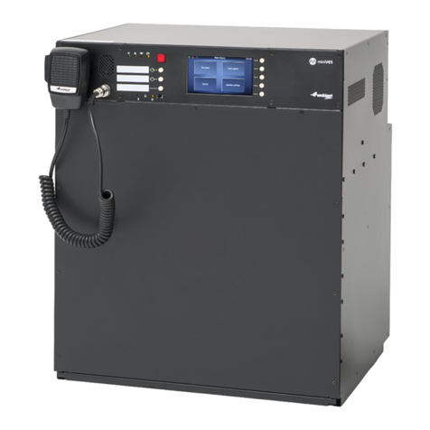
Ambient miniVES User manual

EN 54-16:2008
EN 54-4:1997+AC:1999+A1:2002+A2:2006
User Manual
EN
Compact Voice Alarm System
www.ambientsystem.eu
ver. 11. 2021

Compact Voice Alarm System
User Manual
2
Table of Contents
1. Safety__________________________________________________________________________________ 3
2. miniVES and midiVES front panel ______________________________________________________ 7
2.1 miniVES front panel ______________________________________________________________ 7
2.2 midiVES front panel ______________________________________________________________ 8
2.3 LED colors on the control unit front panel _________________________________________ 8
3. miniVES and midiVES connector panel ________________________________________________ 10
3.1 miniVES L series and midiVES 8003R connector panel _____________________________ 12
3.2 miniVES LN, midiVES 8003 LN and 8003 LNR series connector panel _______________ 13
4. miniVES Charger ______________________________________________________________________ 14
4.1 miniVES Charger ________________________________________________________________ 14
4.2 Batteries _______________________________________________________________________ 16
5. Instructions for performing basic functions___________________________________________ 17
5.1 Alarm mode ____________________________________________________________________ 17
5.2 Failure mode ___________________________________________________________________ 18
6. Technical data ________________________________________________________________________ 19
6.1 miniVES 2001L, 4001L, 4002L ____________________________________________________ 19
6.2 midiVES 8003R _________________________________________________________________ 22
6.3 midiVES 8003LNR , 8003LN ______________________________________________________ 24
7. Mounting instructions ________________________________________________________________ 26
8. Notes _________________________________________________________________________________ 30

3
1. Safety
Danger!
High risk: This symbol indicates an imminently hazardous situation such
as"Dangerous Voltage" insidethe product. If not avoided, this will result
inanelectrical shock, serious bodily injury, or death.
Warning!
Medium risk: Indicates a potentially hazardous situation.
If not avoided, this could result in minor or moderate bodily injury.
Caution!
Low risk: Indicates a potentially hazardous situation.
If not avoided, this could result in property damage or risk of damage to the unit.
1
Read these instructions. All the safety and operating instructions should be read before the
apparatus or system is operated.
2
Keep these instructions. The important safety instructions and operating instructions
should be retained for future reference.
3 Heed all warnings. All warnings on the apparatus and in the operating instructions should
be adhered to.
4 Follow all instructions. All instructions for installation or use/operating should be followed.
5 Do no use this apparatus near water. Do not use this apparatus near water or a moist envi-
ronment – for example, near a bath tub, wash bowl, kitchen sink, or laundry tub, in a wet
basement, near a swimming pool, in an unprotected outdoor installation, or any area which
is classied as a wet location.
6
Clean only with dry cloth. Unplug the apparatus from the outlet before cleaning. Do not use
liquid cleaners or aerosol cleaners.
7
Do not block any ventilation openings. Install in accordance with the manufacturer’s
instructions. Openings in the enclosure, if any, are provided for ventilation and to ensure
reliable operation of the apparatus and to protect it from overheating. These openings must
not be blocked or covered. This apparatus should not be placed in a built-in installation unless
proper ventilation is provided or the manufacturer’s instructions have been adheredto.

Compact Voice Alarm System
User Manual
4
8
Do not install near any heat sources such as radiators, heat registers, stoves, or other
apparatus (including ampliers) that produce heat or in direct sunlight.
9 No naked ame sources, such as lighted candles, should be placed on the apparatus.
10
Do not defeat the safety purpose of the polarized or ground-type plug. A polarized plug
has two blades with one wider than the other. A grounding type plug has two blades and
a third grounding prong. The wider blade or the third prong are provided for your safety.
Ifthe provided plug does not t into your outlet, consult an electrician for replacement of
the obsolete outlet.
11 Protect the power cord from being walked on or pinched particularly at plug, conveni-
ence receptacles, and the point where they exit from the apparatus.
12
Only use attachments/accessories specied by the manufacturer. Any mounting of the
apparatus should follow the manufacturer’s instructions, and should use a mounting acces-
sory recommended by the manufacturer.
13
Use only with the cart, stand, tripod, bracket or table specied by the manufacturer, or
sold with the apparatus. When a cart is used, use caution when moving the cart/apparatus
combination to avoid injury from tip-over. Quick stops, excessive force, and uneven surfaces
may cause the appliance and cart combination to overturn.
14
Unplug this apparatus during lighting storms or when unused for long periods of time.
Not applicable when special functions are to be maintained, such as evacuation systems.
15
Refer all servicing to qualied service personnel. Servicing is required when the apparatus
has been damaged in any way, such as power-supply cord or plug is damaged, liquid has been
spilled or objects have fallen into the apparatus, theapparatus has been exposed to rain or
moisture, does not operate normally, or has been dropped.
16
Avoid mechanical shocks. Strong impacts and shocks may damage the device. Transport the
device carefully and avoid dropping it.
17 The apparatus shall not be exposed to dripping or splashing and that no objects lled
with liquid, such as vases, shall be placed on the apparatus.
18
Batteries (battery pack or batteries installed) shall not be exposed to excessive heat
such as sunshine, re or the like.
Caution! Danger of explosion if battery is incorrectly replaced. Replace only with
the same or equivalent type. Dispose of used batteries according to the environ-
mental law and procedures.
19 Professional installation only. Do not use this equipment in residential applications.
20
Condensation. In order to avoid condensation; wait a few hours before turning on the equip-
ment when it is transported from a cold to a warm space.
21
Hearing damage. For apparatus with audio output, to prevent possible hearing damage,
donot listen at high volume levels for long periods.

5
22
Do not disassemble the device or attempt to repair or modify it. The device does not
include user replaceable components inside the chassis. Opening the chassis and unautho-
rized repairs will void the warranty. Unauthorized substitutions may result in re, electric
shock or other hazards.
23
Safety check. Upon completion of any service or repairs to this apparatus, ask the service
technician to perform safety checks to determine that the apparatus is in proper operating
condition.
Danger!
Overloading – do not overload outlets and extension cords as this can result in a risk
of re or electric shock.
24 Power sources. This apparatus should be operated only from the type of power source indi-
cated on the marking label. If you are not sure of the type of power supply you plan to use,
consult your appliance dealer or local power company. For apparatuses intended to operate
from battery power, or other sources, refer to the operating instructions.
25
Power lines. An outdoor system should not be located in the vicinity of overhead power lines
or other electric light or power circuits, or where it can fall into such power lines or circuits.
When installing an outdoor system, extreme care should be taken to keep from touching such
power lines or circuits, as contact with them might be fatal.
Danger! Object and Liquid entry – never push objects of any kind into this appa-
ratus through openings as they may touch dangerous voltage points or short-out
parts that could result in a fire or electric shock. Never spill liquid of
any kind on the apparatus.
26
Protective grounding. An apparatus with class I construction shall be connected to a power
outlet socket with a protective grounding connection.
Protective earthing. An apparatus with class I construction shall be connected to a mains
socket outlet with a protective earthing connection.
Note for power connections
»
For permanently connected equipment, a readily operable mains plug or all-pole mains switch
shall be external to theequipment and in accordance with all applicable installation rules.
»
For pluggable equipment, the socket-outlet shall be installed near the equipment and
shall be easily accessible.

Compact Voice Alarm System
User Manual
6
This label may appear on the bottom of the apparatus due to space limitations.
Caution! To reduce the risk of electrical shock, DO NOT open covers. Refer servicing to
qualied service personnel only.
Warning!
To prevent re or shock hazard, do not expose units to rain or moisture.
Warning! Installation should be performed by qualied service personnel only in accor-
dance with the National Electrical Code or applicable local codes.
Warning! Power disconnect: If the apparatus is mains powered and a power supply cord
set is provided, the disconnect device is the mains plug of the power cord set.
If an AC DC adapter is provided and the mains plug that is part of the direct plug in device,
the AC DC adapter is the disconnect device. The socket outlet shall be near the apparatus
and shall be easily accessible.
Old electrical and electronic appliances
Electrical or electronic devices that are no longer serviceable must be collected sep-
arately and sent for environmentally compatible recycling (in accordance with the
European Waste Electrical and Electronic Equipment Directive). To dispose of old
electrical or electronic devices, you should use the return and collection systems
put in place in the country concerned.
Only used at altitude not exceeding 2000m.
Only used in non-tropical climate regions.
≤ 2000 m

7
2. miniVES and midiVES front panel
2.1 Front panel of miniVES
Fig. 1.
23 4 10
1
7 8 9
5
6
Front panel of miniVES 2001L, 4001L, 4002L, 2001LN, 4001LN, 4002LN series and
midiVES 8003LN and 8003LNR
1. Handheld reman’s microphone
2. Built in speaker
3. Indicators
a. Power supply indicator (green LED)
b. Failure indicator (yellow LED)
c. Emergency indicator (red LED)
d. Battery failure indicator (yellow LED)
4. Emergency button
5. Congurable function buttons
6. Function button activation LEDs
7. Handheld microphone LED
8. CPU o section
a. CPU o function LED (yellow)
b. CPU o function switch
9. Display – shows control unit’s menu
10. Functional keys, support auxillary functions when navigating the menu
a. HOME – press to return to the fers menu
b. ENTER – press to enter value /select control unit in menu
c. Up arrow – press to navigate in the control unit menu
d. Down arrow – press to navigate in the control unit menu
e. Back – press to return to previous item in the control unit menu

Compact Voice Alarm System
User Manual
8
2.2 Front panel of midiVES 8003R
1 2
5 6
3
4
Fig. 2. Front panel of midiVES 8003R
1. Indicators
a. Power supply indicator (green LED)
b. Failure indicator (yellow LED)
c. Emergency indicator (red LED)
d. Battery power indicator (yellow LED)
2. Emergency button
3. Congurable function buttons
4. Function button activation LEDs
5. Handheld microphone LED
6. CPU o section
a. CPU o function LED (yellow)
b. CPU o function switch

9
2.3 LED colors on the control unit front panel
Graphic
symbol Color miniVES, midiVES
Control Units
green POWER
yellow FAILURE
red Blocking function active
red ALARM
yellow Battery failure
green Handheld microphone active
yellow CPU-o
function active (CPU bypass)

Compact Voice Alarm System
User Manual
10
3. miniVES and midiVES connector panel
Fig. 3.
BUS1 BUS2
IN7IN6IN5IN4IN3IN2IN1
+48 VDC BATT
Audio IN Audio OUT
CLRCLR
+24 VDC
150 mA
+48 VDC
350 mA
TEMP.
SENSOR
LINE ALINE BLINE CLINE DHV AUDIO IN
CHCHCHCHCH
1
BUS1 BUS2
IN7IN6IN5IN4IN3IN2IN1
+48 VDC BATT
Audio IN Audio OUT
CLRCLR
+24 VDC
150 mA
+48 VDC
350 mA
TEMP.
SENSOR
LINE ALINE BLINE CLINE DHV AUDIO IN
CHCHCHCHCH
LINE ALINE BLINE CLINE DHV AUDIO IN
CHCHCHCHCH
2
1
BUS1 BUS2
IN7IN6IN5IN4IN3IN2IN1
+48 VDC BATT
Audio IN Audio OUT
CLRCLR
+24 VDC
150 mA
+48 VDC
350 mA
TEMP.
SENSOR
LINE ALINE BHV AUDIO IN
CHCHCH
LINE ALINE BHV AUDIO IN
CHCHCH
LINE ALINE BHV AUDIO IN
CHCHCH
LINE ALINE BHV AUDIO IN
CHCHCH
24
13
OUT3OUT2OUT1
OUT3OUT2OUT1
OUT3OUT2OUT1
2
Control Card slotsCharger slots
5
8
1
6 7
43
9
10
2001 units
4001 units
4002 units
Line control card arrangement for miniVES systems
BUS1 BUS2
IN7IN6IN5IN4IN3IN2I N1
+48 VD C BATT
Audio I N
CL R
+24 VD C
150 mA
+48 VD C
350 mA
T E M P.
SENSOR
OUT3OUT2OUT1
LINE ALINE BLINE CLINE D HV AUDIO IN
CHCHCHCHCH
1
LINE ALINE BLINE CLINE D HV AUDIO IN
CHCHCHCHCH
2
LINE ALINE BLINE CLINE D HV AUDIO IN
CHCHCHCHCH
3
LINE ALINE BLINE CLINE D HV AUDIO IN
CHCHCHCHCH
4
Control Card slots Charger slots
11
Fig. 4. Line control card arrangement for midiVES 8003 units

11
1. ABT-xCtrLine-4 control card
2. Local audio bus outputs for 4 line control card operation
3. Logic inputs connector
4. Logic outputs connector
5. Audio I/O connector
6. Auxillary power outputs
7. Temperature sensor input jack
8. Main battery connector
9. Two ABT-xCtrLine-4 control cards
10. Four ABT-xCtrLine-2 control cards
11. Four ABT-xCtrLine-44 control cards

Compact Voice Alarm System
User Manual
12
3.1 miniVES L series and midiVES 8003R connector panel
Fig. 5.
BUS1 BUS2
IN7IN6IN5IN4IN3IN2IN1
+48 VDC BATT
Audio IN Audio OUT
CLRCLR
+24 VDC
150 mA
+48 VDC
350 mA
TEMP.
SENSOR
LAN/WAN
LANLAN
OUT3OUT2OUT1
1
4 5
3 76 98 102
Diagram of the connector panel for miniVES series 2001L, 4001L, 4002L and midiVES 8003R
1. Local audio bus outputs for 4 line control card operation
2. Audio input and output (Audio out not available in midiVES 8003R)
3. Logic inputs
4. Auxillary power outputs
5. Battery temperature sensor input jack
6. Main Battery connector
7. Logic outputs
8. 10/100 Mbps Lan/Wan port (PC connection )
9. 10/100/1000 Mbps Lan port
10. 10/100/1000 Mbps Lan port

13
3.2 miniVES LN, midiVES 8003 LN and 8003 LNR series connector
panel
miniVES LN series as well as midiVES 8003LN / LNR are equipped with extended xNET_mini 1GB/
WAN/RS network card. Extended interface provides additional POE port, 2 logical inputs/ outputs
and 2 optional SFP ports for bre or copper redundant connection.
Fig. 6.
BUS1 BUS2
IN7IN6IN5IN4IN3IN2IN1
+48 VDC BATT
Audio IN Audio OUT
CLRCLR
+24 VDC
150 mA
+48 VDC
35 0 mA
TEMP.
SENSOR
LAN/WANRS485
LANLAN PoE
IN1IN2
BA
FIBER
OUT3OUT2OUT1
1
4 5
11813 14
3 76 9 10 122
Diagram of the connector panel for miniVES series 2001LN, 4001LN and 4002LN units
1. Local audio bus outputs for 4 line control card operation
2. Audio input and output
3. Logic inputs
4. Auxillary power outputs
5. Battery temperature sensor input jack
6. Main Battery connector
7. Logic outputs
8. 10/100 Mbps Lan/Wan port (PC connection )
9. 10/100/1000 Mbps Lan port
10. 10/100/1000 Mbps Lan port
11. RS485 Port
12. Additional Logic I/O ports
13. SFP module slot B
14. SFP module slot A

Compact Voice Alarm System
User Manual
14
4. miniVES charger
4.1 miniVES Charger
In order to connect the batteries to the charger use the battery cable supplied with the device.
Besure of proper connection (polarity) between batteries and terminals. Lastly connect the thermis-
tor temperature sensor to the “TEMP SENSOR” jack and place it near installed batteries. Onlyunused
and type compliant batteries (same manufacturer, equivalent capacity and voltage, same manufac-
turing date) may be connected.
Fig. 7.
BUS1 BUS2
IN7IN6IN5IN4IN3IN2IN1
+48 VDC BATT
Audio IN Audio OUT
CLRCLR
+24 VDC
150 mA
+48 VDC
350 mA
TEMP.
SENSOR
LINE ALINE BLINE CLINE DHV AUDIO IN
CHCHCHCHCH
LINE ALINE BLINE CLINE DHV AUDIO IN
CHCHCHCHCH
LAN/WANRS485
LANLAN PoE
IN1IN2
BA
FIBER
2
1
OUT3OUT2OUT1
Connection between VRLA batteries, temp. sensor and miniVES Charger module
cNOTE: It is crucial to connect the batteries to the system before startup.
Once the power supply has been provided, connect loudspeaker lines, logic inputs and
outputs, network devices.
When you make sure all connections have been carried out properly, you can power up the system

15
Connecting midiVES 8003LNR with 8003R:
For connecting midiVES 8003LNR with 8003R we can use a single set of 4x12V (VRLA) batteries which
is shared between 8003LNR and 8003R.
Please remember to set the capacity of the batteries on unit 8003LNR only and select no batteries
option in 8003R when using the same bateries. Bellow are schematic how to connect batteries to
the midiVES 8003LNR and 8003R using dedicated panel:
BUS1 BUS2
IN7IN6IN5IN4IN3IN2IN1
+48VDC BATT
AudioIN Audio O UT
CL R CL R
+24VD C
150 mA
+48VDC
350 mA
TEM P.
SENSOR
LINEALINEBLINECLINED HVAUDIO IN
CHCHCHCHCH
LINEALINEBLINECLINED HVAUDIO IN
CHCHCHCHCH
LAN/WAN RS485
LAN LANPoE
IN1IN2
B A
FIBER
2
1
OUT3OUT2OUT1
BUS1 BUS2
IN7IN6IN5IN4IN3IN2IN1
+48VDC BATT
AudioIN Audio O UT
CL R CL R
+24VD C
150 mA
+48VDC
350 mA
TEM P.
SENSOR
LINEALINEBLINECLINED HVAUDIO IN
CHCHCHCHCH
LINEALINEBLINECLINED HVAUDIO IN
CHCHCHCHCH
LAN/WAN RS485
LAN LANPoE
IN1IN2
B A
FIBER
2
1
OUT3OUT2OUT1
Fig. 8. Connecting midiVES 8003LNR with 8003R with a set of 4x12V batteries

Compact Voice Alarm System
User Manual
16
4.2 Batteries
It is necessary to protect batteries from short-circuit while connecting battery leads. Short-circuit
may lead to system failure. Follow this manual to assure safety while connecting.
Make sure the system power has been switched o before battery is connected.
Once the batteries have been connected, make sure all terminals of all batteries have been
protected against short-circuit.
Connecting batteries
»
Wait over 10 seconds after the power cord was unplugged from AC socket located
on the miniVES main unit.
» Never connect negative cable in the rst place as in the case of short-circuit between battery
positive wire and a device frame or rack cabinet element, a device damage may occur.
» Connect battery negative cable to negative terminal.
cNOTE: Battery bank has to be connected before connecting main power supply.
cIn case of disconnecting batteries and lack of AC power please wait 60 seconds for fully
discharge of miniVES before the battery pack will be reconnected to the system.
Improper connection procedure may lead to charger module damage.

17
5. Instructions for performing basic functions
5.1 Alarm mode
Activating alarm mode
Lift red button ap (alarm button “activate Evacuation”) and press it. However miniVES system is
not equipped with the red button protected by the ap. That means that pressing once the red
button on the front panel of miniVES activates the 5 seconds procedure (Evacuation button starts
blinking RED) during which the system waits for second press of the button. Finishing this two steps
procedure activates Alarm Mode. Green LED indicators will emit light in all sound system zones. The
system enters alarm state and automatically activates all zones. In this state, music background and
zone microphones are disconnected. It is still possible to send automatic alarm messages or via
reman microphone. The system awaits messages to given zones. The alarm state applies until the
programmed as ”cancel alarm” is pressed.
Cancelling alarm
During alarm state, press “Cancel Alarm” button. VASCU enters standby mode, all alarm messages
are muted and background music is restored.
Sending evacuation messages
Activate alarm and select zones. A green LED next to the zone name means the zone is ready to
transmit. Press “Evacuation” button. A constant red indicator next to green zone selection indicator
means that evacuation message is being sent. The evacuation message will be played back in given
zones in a continuous way, until the button “cancel alarm” is pressed.
Sending warning messages
Activate alarm and select zones. A green LED next to the zone name means the zone is ready to
transmit. Press “Warning” button. A ashing red indicator next to green zone selection indicator
means that the warning message is being sent. The warning message will be played back in given
zones in a continuous way, until the button “cancel alarm” is pressed.
Sending verbal messages via microphone
Activate alarm and select zones you wish to be received in. A green LED next to the zone name
means the zone is ready to transmit. Lift the microphone, press and hold “push to talk” button while
speaking.. Speak slowly, loud and clearly.

Compact Voice Alarm System
User Manual
18
Message priorities
Activate alarm and select zones. Press “Warning” button – warning message will be played back in
given zones. Next, press “Evacuation” button – warning message will stop, and evacuation message
will replace it because has a higher priority. Then, press“push to talk” button – all automatic mes-
sages will stop and you will be able to transmit a live message via the reman microphone.
Transmitting automatic messages and microphone messages in various zones
Activate alarm and select one zone. Activate evacuation message or warning message playback
in the given zone. Unselect this zone (green indicator goes out, red one still emits a constant light
or ashes). Select another zone. To send a verbal message, press and hold “Push to talk” button
and speak to the microphone.
Transmitting verbal messages when the central processing unit is faulty – CPU OFF
Set the switch on the front panel in the CPU OFF position. The CPU OFF LED will light up with
a steady green light. Press “push to talk” button and speak to the microphone.
cNOTE! When the switch is in the CPU OFF position, playback of the alarm messages recorded
in the miniVES memory does not work. The processor is bypassed. A direct connection
between devices is created: microphone ampliers loudspeakers. Microphone input is
broadcasted to the entire system. Ampliers operate at maximum amplication – be aware
that this rises the SPL signicantly.
5.2 Failure mode
A ashing yellow FAILURE LED means that one of VAS central unit elements or a loudspeaker
line is damaged. On miniVES devices and ABT-DFMS the system failure will be indicated by an
acoustic signal. When the damage is signaled, press “conrm failure” button to mute the alarm
sound, and the system will register that the failure was conrmed by the Operator (this event will
be recorded in the event log). The failure LED goes out when the system failure is eliminated and
“cancelfailure” button is pressed.
A system maintenance technician or technical service must be notied of any damage immediately.

19
6. Technical data
6.1 miniVES 2001/4001/4002 L/N, 4002LNR
Model miniVES
2001L, 4001L, 4002L
miniVES
2001LN, 4001LN,
4002LN, 4002LNR
Power supply 230V AC, IEC C14 3pin terminal
Power consumption Up to 600 W (depending on conguration)
Number of control slots 4
Message storage
SD HC cards with capacities up to 32GB supported
The included 512MB SLC SDHC card provides more
than 20 min of message time
LCD display 4,3” LCD touch screen
DSP Implemented 3 band parametric EQ
Number of audio inputs 1
Type of audio inputs Unbalanced
Connector type 3 pin phoenix connector
Frequency response 40 Hz… 20 kHz (@1dB) / 400 Hz… 8 kHz (@0,1dB)
Input impedance 250 Ω
Maximum input voltage ≤ 3 Vrms
Number of outputs 1
Type of outputs Balanced
Connector type 3 pin phoenix connector
Frequency response 40 Hz… 20 kHz (@1dB) / 400 Hz… 8 kHz (@0,1dB)

Compact Voice Alarm System
User Manual
20
Harmonic distortion
(THD+IMD) ≤ 0,05%
Headroom 10 dB
SNR ≥ 90 dB
Channel separation ≥ 80 dB
Output impedance 600 Ω
Nominal output level 1 Vrms
Data communication
Standard communication:
Ű 1000BASE-TX/RJ45 CAT5E
cables – 2 ports available
on the connector panel
Ű 100BASE-TX/RJ45 CAT5
cables – 1 port available
on the connector panel,
for connections with an
external network
Communication over large
distances:
Ű 1000BASE X optical bre
Ű 2 ports providing
a redundant connection
Standard communication:
Ű 1000BASE-TX/RJ45 CAT5E
cables – 2ports available
on the connector panel
Ű 100BASE-TX/RJ45 CAT5
cables – 1 port available
on the connector panel,
for connections with an
external network
Fibre module connector
type / bre type
SFP
modules / SC/LC connector
Multimode or single mode
E30 or E90, OM or OM2
Communication with PC PC software: RJ45, twisted pair connection TIA/
EIA568-B via Ethernet protocol
Operating temperature -5°C / +40°C
Operating humidity 15% to 80% (non-condensing)
Storage temperature -20°C / +70°C
Storage humidity 15% to 80% (non-condensing)
This manual suits for next models
1
Table of contents
Other Ambient Security System manuals