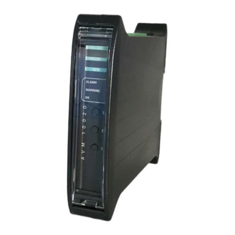
amc VIBRO AV MONITOR 1002DX User manual

amc VIBRO Sp. z o.o.
Pilotow 2e,
31-462 Krakow, Poland
T: +48 (12) 362 97 60
S: + 48 (12) 362 97 63
info@amcvibro.com
KRS No.: 0000618618
REGON No.: 364497010
VAT No.: 6772403385
www.amcvibro.com
AV MONITOR 1002DX
CONDITION MONITORING SYSTEM
WITH RELAY OUTPUTS
USER MANUAL
umEN_02_03.2019

Table of contents
1.
Introduction ...........................................................................................................................................................................
3
2.
Front panel description .....................................................................................................................................................
4
3.
Module dimensions ............................................................................................................................................................
5
4.
Mounting ................................................................................................................................................................................
5
5.
Electrical connectors ...........................................................................................................................................................
6
6.
Strating up ..............................................................................................................................................................................
6
7.
Configuration of AVM 1002DX.......................................................................................................................................
7
7.1
Entering the menu.....................................................................................................................................................
7
7.2
Setting up of the alarm threshold ‘A’ ................................................................................................................
7
7.3
Setting up of the warning threshold ‘U’ ...........................................................................................................
8
7.4
Setting up of the threshold activation delay ‘d’ ............................................................................................
8
7.5
Setting up the latch of alarm or warning threshold violation ‘L’ ............................................................
8
7.6
Signaling of the sensor failure ‘CA’, ‘CU’ ..........................................................................................................
9
7.7
Setting up the correction of values indicated by the module ‘SC’ .....................................................
10
7.8
Turning display off on sensor failure ‘Er’ .......................................................................................................
10
7.9
Selecting the measured vibration signal estimate 'AU‘ ...........................................................................
11
7.10
Relay output state configuration 'uA‘, ‘uU’ ..................................................................................................
11
7.11
Measurement duration ‘C’ ..................................................................................................................................
12
8.
Measurement parameter configuration ..................................................................................................................
12
9.
Menu ......................................................................................................................................................................................
14
10.
Technical parameters .................................................................................................................................................
15
2AV MONITOR 1002DX

1. Introduction
Each module of the AVM 1002DX family is dedicated to another type of application:
a. AV MONITOR 1002DS (AVM 1002DS) is a universal module for reciprocating compressors
which calculates acceleration RMS or 0-Peak analyses for 24 sections of the machine’s rotation
b. AV MONITOR 1002DT (AVM 1002DT) is a module dedicated to ICP®accelerometers with
additional temperature output
The features of AVM 1002DX family modules are as follow:
feature
AVM
AVM
1002DS
1002DT
ICP®(IEPE) standard
✔
x
accelerometer input
temperature input
x
✔
4..20 mA output
proportional to signal
✔
✔
estimate
vibration velocity or
✔
x
acceleration measurement
calculation of RMS or
✔
✔
0-PEAK values
configurable warning and
alarm relay outputs, with the
✔
✔
delay of the output
build-in connector for AC
voltage signal from the
✔
x
vibration sensor (10 Vpp)
DIN rail mounting
✔
✔
vibration sensor failure
✔
x
signaling
RMS or 0-Peak analyses for
24 sections of the machine’s
rotation
✔
x
The AVM 1002DX modules are perfect solution for automated protection systems of rotating machines
with constant and variable rotational speed. The device can be integrated with the controller via the
4..20 mA current output. The 10 Vpp AC voltage output allows to control the vibration level using a
portable vibration analyzer. In addition, the relay outputs can be used as safety features. If alarm level
is exceeded, AVM 1002DX module can turn off the unit before critical damage occurs.
3AV MONITOR 1002DX

2. Front panel description
»Measurement chain diagnostics for IEPE
sensor: Red LEDs (inactive for DT version):
open - open circuit or sensor failure
short - short circuit or sensor failure
»Indicator of the selected
estimate: Green LEDs:
RMS –RMS value of vibration signal
PEAK –maximum value of vibration signal (0-Peak)
»Indicator of the selected measured
value: Green LEDs:
acc –acceleration
vel –velocity
»Alarm outputs indicators:
Red LED:
ALARM –the alarm threshold exceeded, alarm output
ON
Yellow LED:
WARNING –the warning threshold exceeded, warning
ON
»Proper work indicator:
Green OK LED:
diode pulsing with frequency of 1 Hz indicates the
correct operation of the device
rapid pulsing of diode means entering the device setup
menu
»Keyboard:
UP –up
DN - down
SET - set
»Measured value:
double-digit LED display
4AV MONITOR 1002DX

3. Module dimensions
4. Mounting
AVM 1002DX modules are designed for mounting on 35 mm DIN rain in an upright position.
Figure 4-1 // Example of 3 AVM 1002DX modules mounted on DIN rail
5AV MONITOR 1002DX

5. Electrical connectors
Figure 5-1// Connectors description
Figure 5-2 // 4..20 mA current loop connection
6. Starting up
After connecting the power, the AVM 1002DX module enters into testing procedure. Subsequently all
display’s segments and LEDs will flash for a short period of time. If everything is operating properly,
then green OK LED is pulsing with a frequency of approximately 1 Hz. Once the testing procedure is
over, the device is ready to operate. If an error of a sensor circuit is detected, then corresponding LED
will lit.
6AV MONITOR 1002DX

7. Configuration of AVM 1002DX
The front panel of the AVM 1002DX module contains three buttons, labelled subsequently
UP, DN and SET. These buttons are used to edit the module functions.
7.1 Entering the menu
During normal operation of the AVM 1002DX module, pressing UP or DN button will cause
entering into the device menu, which is indicated by rapid blinking of the OK LED. While in
edit mode, buttons UP/DN scroll the menu items:
A –alarm,
U –warning,
d –thresholds activation delay,
L –latching of alarm threshold or warning threshold violation,
CA –alarm activation in case of the sensor circuit failure,
CU –warning activation in case of the sensor circuit failure,
SC –correction of values indicated by the module,
Er –turning display off on sensor failure,
AU –selection of vibration signal estimate,
ATTENTION! In some types of AVM 1002DX modules some of the above functions are not
active.
7.2 Setting up of the alarm threshold ‘A’
The AVM 1002DX has the ability to activate the built-in relay, when the signal from the vibration
sensor exceeds the threshold value.
To set the alarm threshold one should perform the following procedure:
1. Press UP/DN. Afterwards the OK LED will blink rapidly, which indicates entering into the
device menu.
2. By pressing UP/DN set the letter ‘A’ on the display.
3. Confirm by pressing the SET button.
4. Use the UP/DN buttons to select the desired alarm threshold value in the range from 0.0 to
99. Alarm threshold value cannot be lower than the warning threshold value.
5. To confirm the change, press the SET button.
7AV MONITOR 1002DX

If the vibration sensor signal will exceed the alarm threshold value and will remain above it for the time
the configured delay, the alarm relay will be activated.
To disable the alarm threshold, instead of the numerical value from the range from 0.0 to 99, set the
‘FF’ value on the display and confirm by pressing the SET button.
7.3 Setting up of the warning threshold ‘U’
The second relay installed in the AVM 1002DX module is marked WARNING. It informs about
excitation of the warning level of the signal.
To set the warning threshold one should perform the following procedure:
1. Press UP/DN. Afterwards the OK LED will blink rapidly, which indicates entering into the
device menu.
2. By pressing UP/DN set the letter ‘U’ on the display.
3. Confirm by pressing the SET button.
4. Use the UP/DN buttons to select the desired warning threshold value in the range from 0.0
to 99. Warning threshold value cannot be greater than the alarm threshold value.
5. To confirm the change, press the SET button.
To disable the warning threshold, instead of the numerical value from the range from 0.0 to 99, set the
‘FF’value on the display and confirm by pressing the SET button.
7.4 Setting up of the threshold activation delay ‘d’
In the AVM 1002DX module the user can define how long the alarm threshold or the warning
threshold should be exceeded before activating the relay output.
To set the delay one should perform the following procedure:
1. Press UP/DN. Afterwards the OK LED will blink rapidly, which indicates entering into the
device menu.
2. By pressing UP/DN set the letter ‘d’ on the display.
3. Confirm by pressing the SET button.
4. Use the UP/DN buttons to select the desired delay time in the range from 0to 16 s.
5. To confirm the change, press the SET button.
7.5 Setting up the latch of alarm or warning threshold violation ‘L’
AVM 1002DX has the ability to store the information about the violation of the warning or the alarm
threshold. When the violation occurs, after the delay ‘d’, proper relay is activated until the user erases
the violation information by pressing the SET button.
To set up the latch one should perform the following procedure:
1. Press UP/DN. Afterwards the OK LED will blink rapidly, which indicates entering into the
device menu.
2. By pressing UP/DN set the letter ‘L’ on the display.
3. Confirm by pressing the SET button.
4. Use the UP/DN buttons to select the ON option.
5. To confirm the change, press the SET button.
8AV MONITOR 1002DX

To turn off the latch one should perform the following procedure:
1. Press UP/DN. Afterwards the OK LED will blink rapidly, which indicates entering into the
device menu.
2. By pressing UP/DN set the letter ‘L’ on the display.
3. Confirm by pressing the SET button.
4. Use the UP/DN buttons to select the ‘oF’ option.
5. To confirm the change, press the SET button.
7.6 Signaling of the sensor failure ‘CA’, ‘CU’
For full control of the measurement chain AVM 1002DX can activate alarm/warning outputs when the
measurement chain or vibration sensor is damaged.
Sensor failure alarm can be attributed to the triggering alarm or warning relay. Triggering of the relay
occurs after 5 seconds of open/short sensor failure.
To set up the sensor failure signaling on the alarm output one should perform the following
procedure:
1. Press UP/DN. Afterwards the OK LED will blink rapidly, which indicates entering into the
device menu.
2. By pressing UP/DN set the ‘CA’on the display.
3. Confirm by pressing the SET button.
4. Use the UP/DN buttons to select the ON option.
5. To confirm the change, press the SET button.
To set up the sensor failure signaling on the warning output one should perform the following
procedure:
1. Press UP/DN. Afterwards the OK LED will blink rapidly, which indicates entering into
2. the device menu.
3. By pressing UP/DN set the ‘CU’on the display.
4. Confirm by pressing the SET button.
5. Use the UP/DN buttons to select the ON option.
6. To confirm the change, press the SET button.
To turn off the sensor failure signaling ‘CA’/’CU’one should perform the following procedure:
1. Press UP/DN. Afterwards the OK LED will blink rapidly, which indicates entering into the
device menu.
2. By pressing UP/DN set the ‘CA’/’CU’on the display.
3. Confirm by pressing the SET button.
4. Use the UP/DN buttons to select the ‘oF’option.
5. To confirm the change, press the SET button.
9AV MONITOR 1002DX

7.7 Setting up the correction of values indicated by the module ‘SC’
The AVM 1002DX module is designed to work with ICP® (IEPE) accelerometers with sensitivity of 100
mV/g, however it is possible to set up set correction of values indicated by the module to adjust the
module to a sensor with sensitivity slightly different than 100 mV/g. The ‘SC’parameter indicates how
much the presented values are being increased or decreased.
To set correction of values indicated by the module one should perform the following procedure:
1. Press UP/DN. Afterwards the OK LED will blink rapidly, which indicates entering into the
device menu.
2. By pressing UP/DN set the ‘SC’on the display.
3. Confirm by pressing the SET button.
4. Use the UP/DN buttons to select the desired correction value within the -50 up to +50
range. Negative values are indicated by glowing decimal point on the right display.
5. To confirm the change, press the SET button.
7.8 Turning display off on sensor failure ‘Er’
The AVM 1002DX module enables to mask the incorrect measurement values in the case of sensor
circuit failure. Activating this feature results in display of the “--“ symbol in the case of open or short
circuit.
To enable the feature one should perform the following procedure:
1. Press UP/DN. Afterwards the OK LED will blink rapidly, which indicates entering into the
device menu.
2. By pressing UP/DN set the ‘Er’ on the display.
3. Confirm by pressing the SET button.
4. Use the UP/DN buttons to select the ON option.
5. To confirm the change, press the SET button.
To disable the feature one should perform the following procedure:
1. Press UP/DN. Afterwards the OK LED will blink rapidly, which indicates entering into the
device menu.
2. By pressing UP/DN set the ‘Er’on the display.
3. Confirm by pressing the SET button.
4. Use the UP/DN buttons to select the ‘oF’option.
5. To confirm the change, press the SET button.
10 AV MONITOR 1002DX

7.9 Selecting the measured vibration signal estimate 'AU‘
The AVM 1002DX module enables measuring RMS or 0-PEAK values of vibration acceleration or
velocity.
ATTENTION! The configuration must be confirmed using SW1 and SW2 configuration switches
described in the following chapter.
To select desired estimate one should perform the following procedure:
1. Press UP/DN. Afterwards the OK LED will blink rapidly, which indicates entering into the
device menu.
2. By pressing UP/DN set the ‘AU’on the display.
3. Confirm by pressing the SET button.
4. Use the UP/DN buttons to select one of the following option:
»‘PU’–0-PEAK value of the velocity signal,
»‘rU’–RMS value of the velocity signal,
»‘PA’–0-PEAK value of the acceleration signal,
»‘rA’–RMS value of the acceleration signal.
5. To confirm the change, press the SET button.
7.10 Relay output state configuration 'uA‘, ‘uU’
The AVM 1002DF has a special feature to control relay output state (normally open or normally closed).
The configuration can be done independently for warning and alarm output.
To configure relay output state one should perform the following procedure:
1. Press UP/DN. Afterwards the OK LED will blink rapidly, which indicates entering into the
device menu.
2. By pressing UP/DN set on the display letters ‘uU’ for the warning relay or ‘uA’ for the alarm
relay.
3. Confirm by pressing the SET button.
4. Use the UP/DN buttons to select the desired configuration: ‘no’ or ‘nc’.
5. To confirm the change, press the SET button.
The table below displays the effects of the possible settings:
selected
relay output state
startup or
no warning
sensor error
warning or
configuration
power OFF
module error
or alarm
(if enabled)
alarm active
no
open
open
open
closed
closed
nc
open
open
closed
open
open
Figure 7-1 The effects of the possible settings
11 AV MONITOR 1002DX

7.11 Measurement duration ‘C’
This parameter is responsible for the refresh rate of the LED display and value on 4..20 mA current
output. When this parameter is set, the module has to be restarted. It is possible to change the value
from 0.1 to 1 s, every 0.1 s.
8. Measurement parameter configuration
Measurement parameter configuration is set by proper set-up of configuration switches SW1 and
SW2. Description of switches SW1 and SW2 is presented in the following table and Figure 8-1:
Functions of configuration switches
SW 1 SW2
S1
–ON, HPF =10 Hz (OFF = 3 Hz)
S1
–ON, range 10 (OFF, range 100)
S2
–range 100
S2
–ON, range 25 (OFF, range 100)
S3
–range 10
S3
–ON - acceleration (OFF - velocity)
S4
–range 25
S4
–ON - RMS (OFF - PEAK)
S5
–DX: LPF = 1 kHz
S5
–ON, internal power supply +24 V for 4..20 mA
S6
–LPF = 10 kHz
S6
–ON, external power supply for 4..20 mA
S7
–acceleration
S8
–velocity
12 AV MONITOR 1002DX

Picture 8-1 // Functions of configuration switches
Example:
Monitoring of the RMS of the vibration signal velocity, using 3 Hz high pass filter and 10
kHz low pass filter, for 100 mm/s range and internal power loop.
The following configuration of the switches must be set:
SW1
SW2
OFF
ON
OFF
OFF
OFF
ON
OFF
ON
OFF
OFF
OFF
ON
ON
OFF
1
8
1
6
WARNING!
The set-up of the switches configuration should be done on a switched off device. If the set-up
was done on an operating module, it needs to be restarted in order to activate the new
configuration.
13 AV MONITOR 1002DX
Except DT version

9. Menu
Graphical representation of menu structure is presented on the following figure.
14 AV MONITOR 1002DX

ATTENTION! In some types of AVM 1002DX modules some of the above functions are not
active.
10. Technical parameters
PARAMETER
VALUE
sensor type
DX: IEPE, 100 mV/g , 8 mA/20 V
DT: 10 mV/°C
DX: vibration velocity, acceleration
measured values
DT: temperature
types of estimates
RMS, 0-PEAK
power supply
24 VDC (18..36 VDC)
power consumption
<4 W
low-pass filter
DX: 1 and 10 kHz, 24 dB/oct., 4th order
DT: no LPF filter
high-pass filter
DX: 3 and 10 Hz, 12 dB/oct., 2nd order
DT: no HPF filter
insulation
1 kV DC (2 or 3 kV DC optionally)
current output:
2 or 3 wired 4..20 mA current loop
voltage output
AC, 10Vpp max
delay
0 - 16s every 1s
alarm level
0 –99
warning level
0 –99
relay outputs
24 V/100 mA, NO
operating temperature
-20..+60oC
operating relative humidity
<95% RH
protection class
IP20
dimensions
23 x 100 x 120 (W x H x L)
mounting
35 mm DIN rail
15 AV MONITOR 1002DX

10. Recycle
10.1. Hazardous Materials
AVM 2000 devices do not use any hazardous materials outlined by RoHS. These
regulations confirm that lead, mercury, cadmium, hexavalent chromium,
polybrominated biphenyls, polybrominated diphenyl ether, or other battery related
materials are limited to no more than trace amounts.
10.2. Recycling Facilities
When decommissioning out of use devices, minimize the impact of the waste created. Refer to local
waste removal administration for current information on proper material collection and recycling.
Table of contents
Other amc VIBRO Measuring Instrument manuals
Popular Measuring Instrument manuals by other brands

Delmhorst Instrument Co
Delmhorst Instrument Co CX-30 owner's manual

Dickey-John
Dickey-John GAC 2700-UGMA quick start guide

Panasonic
Panasonic k-nl304k user manual

DAKOTA ULTRASONICS
DAKOTA ULTRASONICS MX-5-C Operation manual

SoundWater
SoundWater Orcas Mini Instruction guide

Thermo Scientific
Thermo Scientific ERGOSTAR HM 200 instruction manual