AMCI NEXUS NX2A4E2 User manual

MICRO CONTROLS INC.
ADVANCED
U
s
e
r
M
a
n
u
a
l
Manual #: 940-0N090
E2 Technology

ADVANCED MICRO CONTROLS INC.
GENERAL INFORMATION
Important User Information
The products and application data described in this manual are useful in a wide variety of different applica-
tions. Therefore, the user and others responsible for applying these products described herein are responsible
for determining the acceptability for each application. While efforts have been made to provide accurate infor-
mation within this manual, AMCI assumes no responsibility for the application or the completeness of the
information contained herein.
UNDER NO CIRCUMSTANCES WILL ADVANCED MICRO CONTROLS, INC. BE RESPONSIBLE OR
LIABLE FOR ANY DAMAGES OR LOSSES, INCLUDING INDIRECT OR CONSEQUENTIAL DAM-
AGES OR LOSSES, ARISING FROM THE USE OF ANY INFORMATION CONTAINED WITHIN THIS
MANUAL, OR THE USE OF ANY PRODUCTS OR SERVICES REFERENCED HEREIN.
No patent liability is assumed by AMCI, with respect to use of information, circuits, equipment, or software
described in this manual.
The information contained within this manual is subject to change without notice.
This manual is copyright 2020 by Advanced Micro Controls Inc. You may reproduce this manual, in whole or
in part, for your personal use, provided that this copyright notice is included. You may distribute copies of this
complete manual in electronic format provided that they are unaltered from the version posted by Advanced
Micro Controls Inc. on our official website: www.amci.com. You may incorporate portions of this documents
in other literature for your own personal use provided that you include the notice “Portions of this document
copyright 2020 by Advanced Micro Controls Inc.” You may not alter the contents of this document or charge a
fee for reproducing or distributing it.
Standard Warranty
ADVANCED MICRO CONTROLS, INC. warrants that all equipment manufactured by it will be free from
defects, under normal use, in materials and workmanship for a period of [18] months. Within this warranty
period, AMCI shall, at its option, repair or replace, free of charge, any equipment covered by this warranty
which is returned, shipping charges prepaid, within eighteen months from date of invoice, and which upon
examination proves to be defective in material or workmanship and not caused by accident, misuse, neglect,
alteration, improper installation or improper testing.
The provisions of the "STANDARD WARRANTY" are the sole obligations of AMCI and excludes all other
warranties expressed or implied. In no event shall AMCI be liable for incidental or consequential damages or
for delay in performance of this warranty.
Returns Policy
All equipment being returned to AMCI for repair or replacement, regardless of warranty status, must have a
Return Merchandise Authorization number issued by AMCI. Call (860) 585-1254 with the model number and
serial number (if applicable) along with a description of the problem during regular business hours, Monday
through Friday, 8AM - 5PM Eastern. An "RMA" number will be issued. Equipment must be shipped to AMCI
with transportation charges prepaid. Title and risk of loss or damage remains with the customer until shipment
is received by AMCI.
24 Hour Technical Support Number
24 Hour technical support is available on this product. If you have internet access, start at www.amci.com.
Product documentation and FAQ’s are available on the site that answer most common questions.
If you require additional technical support, call (860) 583-1254. Your call will be answered by the factory dur-
ing regular business hours, Monday through Friday, 8AM - 5PM Eastern. During non-business hours an auto-
mated system will ask you to enter the telephone number you can be reached at. Please remember to include
your area code. The system will page an engineer on call. Please have your product model number and a
description of the problem ready before you call.
Waste Electrical and Electronic Equipment (WEEE)
At the end of life, this equipment should be collected separately from any unsorted municipal waste.

20 Gear Drive, Plymouth Ind. Park, Terryville, CT 06786
Tel: (860) 585-1254 Fax: (860) 584-1973 http://www.amci.com 3
TABLE OF CONTENTS
General Information
Important User Information ..................... 2
Standard Warranty ................................... 2
Returns Policy .......................................... 2
24 Hour Technical Support Number ........ 2
Waste Electrical and Electronic Equipment
(WEEE) .................................................. 2
About this Manual
Audience .................................................. 5
Trademark Notices ................................... 5
Revision Record ....................................... 5
Revision History ............................ 5
Navigating this Manual ............................ 5
Manual Conventions ................................ 5
Where To Go From Here ......................... 6
Reference: NX2A4E2 Introduction
The NX2A4E2 ......................................... 7
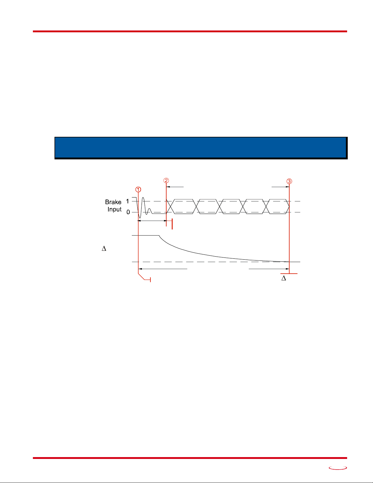
Stop Time Monitoring ............................. 9
NX2A4E2 Programmable Parameters ..... 10
Common Parameters ..................... 10
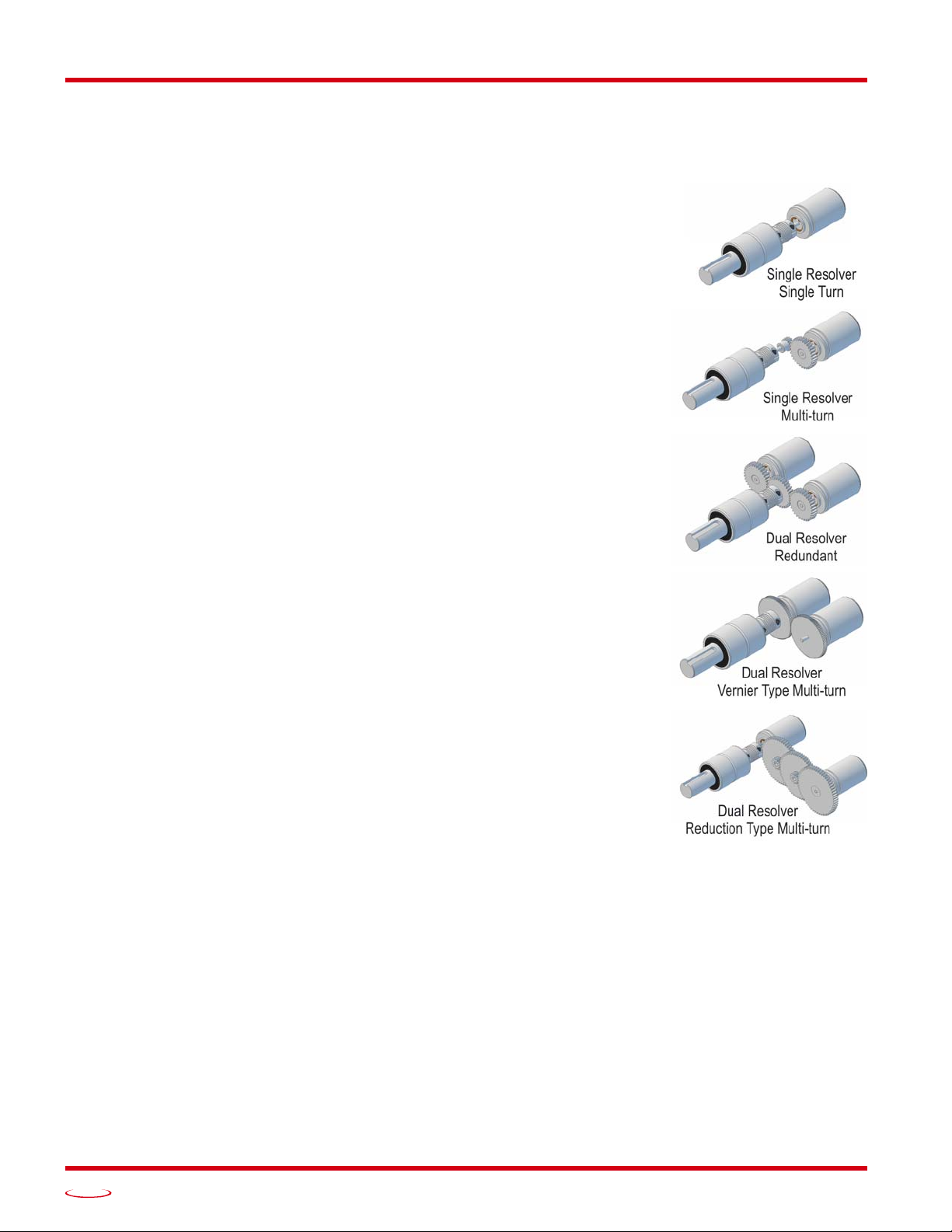
Single Turn Parameters ................. 10
Multi-turn parameters .................... 11
Front Panel Description ........................... 12
Connector Pinout ........................... 12
Status LEDs ............................................. 13
Resolver Status LEDs .................... 13
Ethernet Status LEDs .................... 13
Input Status LEDs .......................... 14
Specifications ........................................... 15
Reference: Data Formats
Mixed Data Formats ................................ 17
Output Data Formats ................................ 17
Single Resolver Data Format ......... 17
Dual Resolver Data Format ........... 20
Input Data Formats .................................. 24
Data Blocks ................................... 24
Multi-word Data Format ................ 24
Single Resolver Data Format ......... 25
Dual Resolver Data Format ........... 26
Reference: Configuring Network
Interfaces
Firewall Settings ....................................... 29
Disable All Unused Network Interfaces .. 29
Configure Your Network Interface .......... 29
Test Your Network Interface ................... 30
Task: Installing the NX2A4E2
Safe Handling Guidelines ........................ 31
Prevent Electrostatic Damage ....... 31
Prevent Debris From
Entering the Unit ........................ 31
Remove Power Before Servicing .. 31
General Wiring Guidelines ...................... 31
Wiring ........................................... 31
Grounding ..................................... 32
Surge Suppression ......................... 32
Mounting ....................................... 32
DIN Rail Mounting .................................. 32
DIN Rail Installation ..................... 32
Attach the DIN Brackets ............... 32
Dimensions ................................... 33
Panel Mounting ........................................ 34
Attach the Panel Mount
Brackets ...................................... 34
Dimensions ................................... 34
Power Wiring ........................................... 35
Network Connections ............................... 35
EtherNet/IP DLR Applications ..... 35
PROFINET MRP Applications .... 35
AMCI Transducers ................................... 36
Transducer Outline Drawings ....... 36
Mounting ....................................... 36
Foreign Transducers ................................. 37
Transducer Connector Pinout ................... 37
Transducer Wiring ................................... 38
Single Resolver Transducers ........ 38
Size 11 and Size 15 Resolvers ...... 39
AMCI Dual Resolver
Multi-turn Transducers ............... 40
Foreign Dual Resolver
Transducers ................................. 40
Avoiding Ground Loops and
Ground Shifts .............................. 41
DC Input Wiring ...................................... 42
Cable Shields ................................ 42

TABLE OF CONTENTS
NX2A4E2 User Manual
ADVANCED MICRO CONTROLS INC.
4
Task: Set the IP Address and
Protocol
Determine the Best Method for
Setting the IP Address ............................ 43
Use Factory Default Settings .................... 43
Use DIP Switches ..................................... 44
Use the Embedded Web Server ................ 45
Use the AMCI NET
Configurator Utility ................................ 47
Task: Installing an EDS File
Obtain the EDS file .................................. 53
Install the EDS file ................................... 53
Start the EDS Hardware
Installation Tool .......................... 53
Install the EDS File ....................... 54
Task: EtherNet/IP Implicit
Communications
Host System Configuration ...................... 57
Add the NX2A4E2 ................................... 57
Check I/O Data Formats ........................... 60
Buffer the Input Data ................................ 60
Configure the NX2A4E2 .......................... 60
Task: EtherNet/IP Explicit
Messaging
Required Message Instructions ................ 61
Create Four New Data Files ..................... 61
Add the Message Instructions
to your Ladder Logic .............................. 62
Troubleshooting ....................................... 65
Task: Modbus TCP Configuration
Enable Modbus TCP Protocol .................. 67
Modbus Addressing .................................. 67
Modbus Table Mapping ................ 67
Host Addressing ............................ 67
AMCI Modbus TCP Memory Layout ...... 68
Supported Number of Connections .......... 68
Supported Modbus Functions ................... 69
Supported Modbus Exceptions ................. 69
Task: PROFINET Network
Configuration
Basic Steps ................................................ 71
Download the GSDML files ..................... 71
GSDML File Installation .......................... 71
Configure the PROFINET Network ......... 71
Add the NX2A4E2 to the
PROFINET Network .............................. 72
Set the I/O Configuration ......................... 74
Verify and Download the
New Configuration ................................. 74
MRP Installations ..................................... 75
Configure the NX2A4E2 as an MRC ....... 75

20 Gear Drive, Plymouth Ind. Park, Terryville, CT 06786
Tel: (860) 585-1254 Fax: (860) 584-1973 http://www.amci.com 5
ABOUT THIS MANUAL
Audience
This manual explains the set-up, installation, and operation of AMCI’s NX2A4E2 Resolver Interface
Module. It is written for the engineer responsible for incorporating these modules into a design, as well as
the engineer or technician responsible for their actual installation.
Trademark Notices
The AMCI logo is a trademark of Advanced Micro Controls Inc. “CIP” is a trademark of Open DeviceNet
Vendor Association, Inc. “EtherNet/IP” is a trademark of ControlNet International, Ltd. under license by
Open DeviceNet Vendor Association, Inc. “PROFINET” is a registered trademark of PROFIBUS & PROFI-
NET International (PI). “Adobe” and “Acrobat” are registered trademarks of Adobe Systems Incorporated.
All other trademarks contained herein are the property of their respective holders.
Revision Record
This manual, 940-0N090, is the first release of this manual. It was released April 23rd, 2020.
Revision History
940-0N090 Initial Release.
Navigating this Manual
This manual is designed to be used in both printed and on-line formats. Its on-line form is a PDF document,
which requires Adobe Acrobat Reader version 7.0+ to open it. The manual is laid out with an even number of
pages in each chapter. This makes it easier to print a chapter to a duplex (double sided) printer.
The PDF file is password protected to prevent changes to the document. You are allowed to select and copy
sections for use in other documents and, if you own Adobe Acrobat version 7.0 or later, you are allowed to
add notes and annotations.
Manual Conventions
Three icons are used to highlight important information in the manual:
NOTES highlight important concepts, decisions you must make, or the implications of those
decisions.
CAUTIONS tell you when equipment may be damaged if the procedure is not followed
properly.
WARNINGS tell you when people may be hurt or equipment may be damaged if the pro-
cedure is not followed properly.
Read this chapter to learn how to navigate through this manual and familiarize
yourself with the conventions used in it. The last section of this chapter highlights
the manual’s remaining chapters and their target audiences.

ABOUT THIS MANUAL
NX2A4E2 User Manual
ADVANCED MICRO CONTROLS INC.
6
Manual Conventions (continued)
The following table shows the text formatting conventions:
Where To Go From Here
You will most likely read this manual for one of two reasons:
If you are curious about the NX2A4E2 Resolver Interface Module from AMCI, this manual contains
the information you need to determine if these product is the right one for your application. The first
chapter, NX2A4E2 Introduction contains all of the information you will need to fully specify the right
product for your application.
If you need to install and use the NX2A4E2 Resolver Interface Module, then the rest of the manual is
written for you. To simplify installation and configuration, the rest of the manual is broken down into
references and tasks. Using this product requires you to complete multiple tasks, and the manual is bro-
ken down into sections that explain how to complete each one.
Format Description
Normal Font Font used throughout this manual.
Emphasis Font Font used the first time a new term is introduced.
Cross Reference When viewing the PDF version of the manual, clicking on
the cross reference text jumps you to referenced section.
HTML Link When viewing the PDF version of the manual, clicking on
the link will connect you with the www.amci.com website.
Chapter Title Page Intended Audience
NX2A4E2 Introduc-
tion 7Anyone new to the NX2A4E2. This chapter gives a basic overview
of the features available on the unit, typical applications, and spec-
ifications.
Data Formats 17 Anyone that needs detailed information on the data formats used
by the NX2A4E2 to communicate with its host controller.
Configuring Network
Interfaces 29 Basic information on configuring a PC or laptop to successfully
communicate with an NX2A4E2 to set its IP address.
Installing the
NX2A4E2 31 Anyone that must install an NX2A4E2 on a machine. Includes
information on mounting, grounding, and wiring specific to the
units.
Set the IP Address
and Protocol 43 Anyone that needs to change the IP address or communications
protocol used by the NX2A4E2.
Installing an EDS
File 53 Anyone that needs information on installing an EDS file for use on
EtherNet/IP systems. An Allen-Bradley controller is used as an
example.
EtherNet/IP Implicit
Communications 57 Anyone that needs information on configuring Implicit Messaging
on an EtherNet/IP system. An Allen-Bradley controller is used as
an example.
EtherNet/IP Explicit
Messaging 61 Anyone that needs information on configuring Explicit Messaging
on an EtherNet/IP system. An Allen-Bradley controller is used as
an example.
Modbus TCP
Configuration 67 Anyone using Modbus TCP to communicate with the NX2A4E2.
PROFINET Network
Configuration 71 Anyone using PROFINET to communicate with the NX2A4E2. A
Siemens SIMATIC controller is used as an example.

20 Gear Drive, Plymouth Ind. Park, Terryville, CT 06786
Tel: (860) 585-1254 Fax: (860) 584-1973 http://www.amci.com 7
REFERENCE 1
NX2A4E2 INTRODUCTION
The NX2A4E2
The NX2A4E2 is a member of the growing line of products from AMCI that incorporate our E2 Technology.
E2 Technology by AMCI is an innovative new multi-protocol approach to Ethernet distributed I/O.
E2 Technology products are simple and intuitive, allowing easy transition between Ethernet/IP, PROFINET,
or Modbus/TCP protocols without the need to physically switch parts. An advanced web server integrated
into all AMCI E2 Technology devices facilitates simple network configuration and troubleshooting via a
web-browser. Furthermore, an impressive array of advanced features for each supported protocol has been
incorporated into the devices to meet many unique application requirements.
The NX2A4E2 is a four channel resolver interface module that allows you to lower transducer wiring cost by
placing the NX2A4E2 close to the transducers and running a single network cable back to the host controller.
The NX2A4E2 also future-proofs your resolver feedback design. The host controller can be updated to any
future platform that supports EtherNet/IP, PROFINET, or Modbus TCP and the NX2A4E2 will operate with
the new system.
The NX2A4E2 can be programmed to accept up to four single resolver transducers, or two dual-resolver
transducers. Single resolver transducers are typically single turn devices, but can have a gear train between
the input shaft and the internal resolver. Dual-resolver transducers are designed for high resolution, multi-turn
applications. The NX2A4E2 can also be programmed to accept two single resolver transducers and one dual-
resolver transducer. This setup is advantageous in several industries, such a press automation. This unit gives
press builders crankshaft angle indication on a single-turn channel and shut height indication on the multi-
turn channel, combining the functions of two separate boxes or modules into one. To further aid press integra-
tors, the NX2A4E2 also includes a brake input that can be used to measure crankshaft stopping time.
Each unit has two Ethernet ports which are internally connected through an onboard, two port, 10/100 Mbps
ethernet switch. These ports allow you to wire your network in a “daisy-chain” fashion, which may lower net-
work wiring costs and complexities.
The two ports also allow the units to function as members of a redundant Device Level Ring (DLR) network
when using the EtherNet/IP protocol or as clients in a Media Redundancy Protocol (MRP) network when
using PROFINET.
In DLR environments, the units act as Beacon-Based Ring Nodes. All units can process beacon packets at the
default rate of every 400 microseconds. Beacon-based nodes can respond faster to network changes than
nodes that only process Announce packets.
This reference section contains the information you need to decide if the
NX2A4E2 Resolver Interface Module is the right product for your application.

NX2A4E2 INTRODUCTION
NX2A4E2 User Manual
ADVANCED MICRO CONTROLS INC.
8
The NX2A4E2 (continued)
As briefly described above, NX2A4E2 can be programmed to accept multiple types of resolver based trans-
ducers:
Single Resolver Transducers - This type of transducer has a single
resolver in the transducer package. This type includes transducers that
yield an absolute position over a single turn, such as our HT-20,
HT-400, H25, and R11 product lines, and transducers that include an
integral gear train between the input shaft and the resolver so they can
yield an absolute position value over multiple turns. An example of this
type of transducer is any member of the HT-20-(x) line from AMCI.
Redundant Resolver Transducers - This type of transducer has two
resolvers that are geared 1:1 with the input shaft. Examples of a redun-
dant resolver transducer are the HTT-20-1 and HTT-400-1A-J/J from
AMCI. These transducers are typically used in systems that require
redundant controls for safety or high availability. To the NX2A4E2,
these transducers appear as two single resolver, single turn, transducers.
Dual Resolver Transducers - This type of transducer has two resolvers
in the transducer package that are geared in such a way that the trans-
ducer yields a high resolution absolute position over multiple turns. As
shown in figure R1.1 to the right, there are two types of dual resolver
multi-turn transducers. One type uses a vernier gearing, where the two
gears differ by one tooth. Examples of this type of transducer are the
HTT-20-100, HTT-20-180, HTT-20-1000 and HTT-20-1800 transducers
from AMCI. The second type uses a gear reduction between the fine and
coarse gear so that the coarse gear completes one rotation for multiple
turns of the fine resolver.
The NX2A4E2 accepts programming information and reports position, veloc-
ity, and error information over the network connection. This connection means
that you do not have to be physically near the NX2A4E2 while configuring it.
All configuration and setup data is sent from your host system over the net-
work connection. This allows you to:
Configure the NX2A4E2 from anywhere
Store multiple setups on your machine
Copy setup data from one machine to another
Design custom HMI interfaces for configuration and setup that can sim-
plify machine training, startup, and repair.
Figure R1.1 Resolver Transducer
Types

20 Gear Drive, Plymouth Ind. Park, Terryville, CT 06786
Tel: (860) 585-1254 Fax: (860) 584-1973 http://www.amci.com
NX2A4E2 User Manual
NX2A4E2 INTRODUCTION
9
Stop Time Monitoring
If you are using the NX2A4E2 in a press control application, you can use the stop time monitoring feature to
measure the stopping time of the crankshaft. The stop time monitor on the unit measures the time between the
on-to-off transition of the Brake Input and the stopping of the transducer attached to channel one. Note that
channel one must be configured as a single-turn channel to use the stop time monitor. The Stop Time Timer
measures a stopping time of 34 milliseconds to 9.999 seconds with a resolution of 1 millisecond.
The NX2A4E2 also captures the position at which the brake is applied and reports this information, along
with the stopping time, when a brake cycle is completed. This information is reported over the network until
the next brake cycle finishes.
If you are not using the unit in a press control application, you can leave the Brake Input un-wired and the
Stop Time monitor will never be triggered.
Figure R1.2 below shows how the stopping time is measured.
Figure R1.2 Stop Time Measurement
1) The NX2A4E2 captures the Brake Applied Position and starts the Stop Time Timer when the Brake Input
makes a 10 (onoff) transition. The Brake Applied Position is not immediately placed in the input data.
It is updated, along with the Stop Time, when the brake cycle completes.
If the Brake Input returns to its normal state for sixteen milliseconds in the next thirty-four, the
input transition is considered noise and the brake cycle is aborted. The next transition on the
Brake Input starts another brake cycle.
If the Brake Trigger Input is not in its active state for twelve of the last sixteen milliseconds of
the thirty-four millisecond debounce time, the input transition is considered noise and the brake
cycle is aborted. If the input is in its active state at the end of the thirty-four milliseconds, the
brake cycle will begin again immediately. If the input is in its normal state, the brake cycle will
start on the next transition.
2) Once the debounce time is exceeded, the state of the brake trigger is ignored until the brake cycle is
complete. From this point on, the Stop Time timer runs until the transducer position stops changing. The
‘Position’ section of the diagram shows the press coming to a stop.
3) The Stop Time timer stops when the change in position value equals zero. The transducer is considered
stopped when there is less than 1/2,048th of a rotation made in 125 milliseconds. This translates into less
than one turn every 4.2 minutes. Obviously, it takes 125 milliseconds to determine that the position has not
changed for that amount of time. Therefore, the Stop Time timer runs until the transducer does not move
for 125 milliseconds, and it then subtracts 125 milliseconds from the Stop Time value.
The stop time monitor is a monitoring feature only. Any determination of correct brake
operation must be made by the host controller through a user developed program.
Debounce Time
Brake Trigger Input = 33 mSec
Measured Stop Time
Brake Applied Position
Position
P=0
Input State is 'Don't Care' from the end of the
Debounce Time until press has stopped.

NX2A4E2 INTRODUCTION
NX2A4E2 User Manual
ADVANCED MICRO CONTROLS INC.
10
NX2A4E2 Programmable Parameters
Common Parameters
These parameters are available on the NX2A4E2 regardless of the type of transducer used.
Resolver Type
This global parameter configures the NX2A4E2 for AMCI transducers, or transducers from AVG/Autotech or
Gemco. This parameter alters the reference voltage to the resolvers so that the return signals are compatible
with the NX2A4E2 resolver inputs. Therefore, you cannot mix resolver types when using this parameter. If
you need to interface both resolver types to the NX2A4E2, you will have to purchase a separate item from
AMCI with the part number RM-3. The RM-3 Reference Module is a single ended transformer that wires into
the transducer cable and alters the reference voltage for the foreign transducers.
AMCI also offers the RM-1 Reference Module to interface Namco/C&A transducers with the
NX2A4E2, and the RM-5 to interface Reliance or Tamagawa resolvers.
Enable Channel Status LED
These four parameters allow you to selectively disable the status LED’s on channels you are not using in your
application.
Transducer Fault Latch
This parameter is available on each transducer input channel and gives you programmable control over
whether or not transducer faults are self clearing or latched. Self clearing faults clear themselves as soon as
the resolver signals return to valid values. Latched faults must be cleared by the host. The factory default set-
ting is for self clearing faults.
Count Direction
This parameter is available on each transducer input channel and gives you programmable control over the
direction of rotation needed to produce increasing counts. When you use AMCI transducers that are wired as
shown in this manual, the factory default setting is for clockwise increasing counts when looking at the trans-
ducer shaft.
Tachometer Response
This parameter is available on each transducer input channel and gives you programmable control over the
update time of the tachometer value. The Tachometer Response can be programmed to 120 milliseconds or 24
milliseconds, and is 120 milliseconds by default. Note that this parameter only affects the update time of the
tachometer value. It does on affect the position update time, which is always 200 microseconds.
Single Turn Parameters
These parameter are available when the module is used with single resolver or redundant resolver transduc-
ers.
Full Scale Count
This parameter allows you to set the number of counts reported by the NX2A4E2 for a full rotation of the
resolver. This parameter has a range of 2 to 8,192, with a factory default of 1,024.

20 Gear Drive, Plymouth Ind. Park, Terryville, CT 06786
Tel: (860) 585-1254 Fax: (860) 584-1973 http://www.amci.com
NX2A4E2 User Manual
NX2A4E2 INTRODUCTION
11
NX2A4E2 Programmable Parameters (continued)
Single Turn Parameters (continued)
Linear Offset
The Linear Offset parameter changes the range of count values output by the unit and is used when the trans-
ducer position directly correlates to a linear measurement that does not start at zero. One such example is an
overhead crane. Another example is a press shut height measurement.
As an example of how the Linear offset works, when the Full Scale Count is set to 1,500 and the Linear Offset
is set to zero, the NX2A4E2 will output position values from 0 to 1,499. If the Linear Offset is changed to
100, then the unit will then output values from 100 to 1,599.
The default Linear Offset is zero.
For single-resolver channels, the Linear Offset range is 0 to (32,767 – Full Scale Count).
Preset Value
The transducer position can be set to any value within the range of Linear Offset to (Linear Offset +(Full
Scale Count – 1)). This parameter sets the value the transducer position is set to when the host controller
issues the Apply Preset command. This parameter has a factory default value of zero.
Multi-turn parameters
These parameters are available when the module is used with dual resolver, multi-turn transducers.
Transducer Type
This parameter defines the type of dual resolver transducer attached to the NX2A4E2. This parameter has five
values: 100, 180, 1,000, 1,800, and 128. The 100, 180, 1,000, and 1,800 values program the module to inter-
face with AMCI vernier style transducers. The 128 value programs the module to use reduction style trans-
ducer such as those available from AVG/Autotech. The Resolver Type parameter determines the type of
resolver used with the NX2A4E2 and affects the values that can be programmed into this parameter.
Number of Turns
This parameter defines the number of turns the transducer shaft must complete before the position value
returns to zero. The acceptable values are dependant on the value of the Transducer Type parameter.
Table R1.1 Number of Turns Parameter Settings
Full Scale Count
This parameter allows you to set the number of counts reported by the NX2A4E2 over the programmed Num-
ber of Turns. This parameter has a range of 2 to (4,096 * Number of Turns) for 100, and 180 turn transducers
and 2 to (409.6 * Number of Turns) for 1,000 and 1,800 turn transducers. For 128 turn transducers, the range
is 2 to (1,024 * Number of Turns). As an example, assume an HTT-20-180 transducer and the programmed
Number of Turns is 36. The range of the Full Scale Count Parameter is 2 to 147,456. (4,096*36)
Transducer Type
Parameter Setting Number of Turns
Acceptable Values
100 1, 2, 4, 5, 10, 20, 25, 50, 100
180 1, 2, 3, 4, 5, 6, 9, 10, 12, 15,18, 20, 30,
36, 45, 60, 90, 180
1000 10, 20, 40, 50, 100, 200, 250, 500, 1,000
1800 10, 20, 30, 40, 50, 60, 90, 100, 120, 150,
180, 200, 300, 360, 450, 600, 900, 1,800
128 1, 2, 4, 8, 16, 32, 64, 128

NX2A4E2 INTRODUCTION
NX2A4E2 User Manual
ADVANCED MICRO CONTROLS INC.
12
NX2A4E2 Programmable Parameters (continued)
Multi-turn Parameters (continued)
Linear Offset
The Linear Offset parameter changes the range of count values output by the unit and is used when the trans-
ducer position directly correlates to a linear measurement that does not start at zero. One such example is an
overhead crane. Another example is a press shut height measurement.
As an example of how the Linear offset works, when the Full Scale Count is set to 15,000 and the Linear Off-
set is set to zero, the NX2A4E2 will output position values from 0 to 14,999. If the Linear Offset is changed
to 10,000, then the unit will then output values from 10,000 to 24,999.
The default Linear Offset is zero.
For dual-resolver channels, the Linear Offset range is 0 to 999,999.
Preset Value
The transducer position can be set to any value within the range of Linear Offset to (Linear Offset + (Full
Scale Count – 1)). This parameter sets the value the transducer position is set to when the host controller
issues the Apply Preset command. This parameter has a factory default value of zero.
Front Panel Description
Figure R1.3 shows the front panel layout of the NX2A4E2 Resolver Interface. Note that the unit ships with
four Phoenix Contact connectors that are not shown for clarity. The RS485 channel, which is not imple-
mented at this time, does not ship with a connector
Figure R1.3 Front Panel Layout
Connector Pinout
Connector pinout and wiring is given in the appropriate section of the Installing the NX2A4E2 chapter, start-
ing on page 31.
Section 1.4, Power Wiring, is on page 35.
Section 1.5, Network Connections, starts on page 35.
Section 1.8, Transducer Connector Pinout, which starts on page 37, begins the sections on transducer
wiring.
Section 1.10, DC Input Wiring, starts on page 42.
Additional sections of the installation chapter, such as Safe Handling Guidelines, and General Wiring
Guidelines, must be reviewed and adhered to when actually installing the unit.
12
NEXUS
RESOLVER
POWER INPUT AND
CHASSIS GROUND
RESOLVER
STATUS LED's
DC INPUTS AND STATUS LED's
Brake Input Tied To Resolver 1.
Preset Input Not Presently Implemented.
RS485 COMM CHANNEL
For Future Expansion
Not Presently Implemented
MODULE
STATUS LED's
T
RANSDUCER INPUT CONNECTORS
Each Connector Accepts (2) Single-Turn or
(1) Multi-turn Transducer.
ETHERNET RJ45 CONNECTOR
Port 1
ETHERNET RJ45 CONNECTOR
Port 2
DIP SWITCH BANK
Optionally sets IPAddress
LINK2
PORT 2 PORT 1
MS
NS LINK1
12345678

20 Gear Drive, Plymouth Ind. Park, Terryville, CT 06786
Tel: (860) 585-1254 Fax: (860) 584-1973 http://www.amci.com
NX2A4E2 User Manual
NX2A4E2 INTRODUCTION
13
Status LEDs
Resolver Status LEDs
Each resolver channel has a status LED on the front panel.
Table R1.2 Transducer Status LED Patterns
Ethernet Status LEDs
Module Status (MS) LED
The Module Status LED is a bi-color red/green LED. The unit will blink the Module Status LED green during
initialization. After initialization, the state of the LED depends on the state of the network adapter module.
Table R1.3 Module Status LED States
LED State Description
Off The LED has been disabled.
All ON Red Module Fault. This state cannot be disabled.
Blinking Red Non-clearable transducer fault on the channel. This
state can be disabled if the channel is not used.
Blinking Green Latched, clearable transducer fault on the channel.
This state can be disabled if the channel is not used.
Solid Green The channel is not in fault and is reporting position
data. This state can be disabled if the channel is not
used.
LED State EtherNet/IP Definition Modbus TCP Definition PROFINET Definition
Off No Power No Power No power
Alternating
Red/Green
Initializing: Power up Self-Test
Communications failure. There is a communications error between the main processor and
the ethernet co-processor within the unit. You must cycle power to the NX2A4E2 to
attempt to clear this fault.
Flashing
Green Initializing: Waiting for valid physical connection to the
network.
Steady Green Module and Network are operational. Device Name or IP Address
are set.
Flashing Red
Initializing: IP Address conflict Initializing: Device Name or
IP Address are not set.
If the Network Status LED is also flashing, the IP Address or Network Protocol has been
changed. Cycle power to the unit to continue. If the Network Status LED is in any other
state, a write to flash memory has failed. Cycle power to the unit to clear this fault.

NX2A4E2 INTRODUCTION
NX2A4E2 User Manual
ADVANCED MICRO CONTROLS INC.
14
Status LED’s (continued)
Ethernet Status LEDs (continued)
Network Status (NS) LED
The Network Status LED is a bi-color red/green LED. The state of the LED depends on the protocol the
NX2A4E2 is configured to for.
Table R1.4 Network Status LED States
Link1 and Link2 LEDs
These are the Link Activity LEDs for the two ports. They are amber LEDs that are on when a valid hardware
connection exists on the port and blinking when data is being transferred over the link.
Input Status LEDs
These two red/green bi-color LED’s are used to indicate the on/off
status of the BRAKE and PRESET inputs. Note that the PRESET
function is not presently implemented. LED 2 will come on when
power is applied to the PRESET input, but the NX2A4E2 will not
change any position values. The BRAKE input is tied to channel 1.
When this input transitions from on to off, the unit starts a timer
and stops the timer when it does not detect a change in position on
channel 1 for 125 milliseconds. It then reports this time over the
network along with the channel 1 position when the input transi-
tioned. See Stop Time Monitoring found on page 9, for a complete
description of how the brake input is used.
LED State EtherNet/IP Definition Modbus TCP Definition PROFINET Definition
Off No Power No power or no TCP
connections
No power, duplicate IP
address on the network,
mismatch in Device Name,
or no connection to IO
Controller.
Alternating
Red/Green Power up Self-Test Power up Self-Test Power up Self-Test
Blinking
Green Ethernet connection, but
no CIP connections
Indicates number of connec-
tions with 2 second delay
between group. The
NX2A4E2 supports up to
five concurrent connections.
On-line, Stop state. A
connection with the IO
Controller is establishedand
it is in its STOP state.
Steady Green Valid Ethernet network
and CIP connections Not Implemented On-line, Run state. A
connection with the IO
Controller is establishedand
it is in its RUN state.
Blinking Red
If the MS LED is steady
green: Network
Connection Timeout Not Implemented Not Implemented
If the MS LED is blinking green: IP Address or Network Protocol changed: Cycle
power
Steady Red Duplicate IP address on network. Not Implemented.
INPUT STATUS LED's
1: Brake Input
2: Preset Input (Not Implemented)
OFF: No Power Applied
RED: Power Applied, Pin 1/3 is
positive with respect to pin 2/4.
GREEN: Power Applied, Pin 2/4 is
positive with respect to pin 1/3.
12
Figure R1.4 Input Status LEDs

20 Gear Drive, Plymouth Ind. Park, Terryville, CT 06786
Tel: (860) 585-1254 Fax: (860) 584-1973 http://www.amci.com
NX2A4E2 User Manual
NX2A4E2 INTRODUCTION
15
Specifications
Sensor Type
Resolver Transmitters and similar sensors with
sine/cosine stator outputs such as variable
reluctance transducers.
Measurement Method
Ratiometric. Compensates for, and eliminates,
most sources of error, including phase shift,
voltage drift, electrical noise, and temperature
changes.
Number of Input Channels
Four. The NX2A4E2 can interface with four inde-
pendent single resolver transducers, two dual
resolver transducers, or a mix of two single
resolver transducers and one dual resolver trans-
ducer
Number of I/O Words (16 bits each)
21 input words and 10 output words
Transducer Input Isolation
Transformer Isolated
Position Resolution
13 bit (8,192) maximum per turn for single
resolver transducers.
12 bit (4,096) maximum per turn for AMCI
100 and 180 turn dual resolver multi-turn
transducers.
409.6 maximum counts per turn for AMCI
1,000 and 1,800 turn dual resolver multi-turn
transducers.
10 bit (1,024) maximum per turn for foreign dual
resolver multi-turn transducers.
Position Update Time
200 microseconds
Tachometer Resolution
1 RPM
Tachometer Update Time
Programmable to 24 or 120 milliseconds
Stop Time Monitor
On board timer measures the time between the on
to off transition of a digital input and the cessa-
tion of movement on transducer channel one.
Channel one must be configured for a single-
turn transducer.
Most commonly used in press applications to mon-
itor brake functionality.
Stop Time Digital Input
10 to 30 Vdc isolated input. Requires 10 mA
minimum to operate
Nonvolatile Memory
EEPROM. Used to store configuration data and
position offsets. 100,000 write cycles minimum.
Physical Dimensions
Width: 5.75 inches
Depth: 3.96 inches w/o mating connectors
Height: 3.04 inches
Additional clearance needed based on mounting
configuration
NX2A4E2 Mounting
DIN rail or panel mount. Kit included with unit
that allows customer to change mounting styles.
DIN channel can be EN 50 002 or EN 50 035.
Input Power
24 Vdc ± 10%, surge to 30Vdc without damage to
unit. Requires 12 watts. (0.5A @ 24Vdc)
Environmental Specifications
Ambient Operating Temperature
............ 32° to 140°F (0° to 60°C)
Storage Temperature
............ -40° to 185°F (-40° to 85°C)
Humidity ............ 0 to 95%, non-condensing
Status LEDs
See Status LEDs starting on page 13.
Connectors
Mating connectors are included with the
NX2A4E2
Connector AMCI Part # Wire Strip Length Min. Tightening Torque
Resolver I/O MS-8 28 - 12 AWG 0.394 inches 4.43lb-in (0.5 Nm)
Digital I/O MS-4 28 - 12 AWG 0.394 inches 4.43lb-in (0.5 Nm)
Power MS-3W 28 - 12 AWG 0.394 inches 4.43lb-in (0.5 Nm)

NX2A4E2 INTRODUCTION
NX2A4E2 User Manual
ADVANCED MICRO CONTROLS INC.
16
Notes

20 Gear Drive, Plymouth Ind. Park, Terryville, CT 06786
Tel: (860) 585-1254 Fax: (860) 584-1973 http://www.amci.com 17
REFERENCE 2
DATA FORMATS
Mixed Data Formats
The NX2A4E2 allows you to work with up to four single resolver transducers, up to two dual resolver trans-
ducers, or one dual resolver transducer along with up to two single resolver transducers.
Output data is used to program the channels and preset the transducer position values. Only one channel can
be programmed at a time, so the description of the two formats is straight forward.
If the NX2A4E2 is programmed for a dual resolver multi-turn transducer, and either of the two
input channels is later programmed as a single resolver channel, then both of the channels of the
dual resolver multi-turn transducer input will be re-programmed with the single resolver data.
For example, if channels 3 and 4 are programmed as a dual resolver multi-turn channel, and
channel 4 is later programmed as a single resolver channel, then channels 3 and 4 both become
single resolver channels and the programming for channel 4 is also applied to channel 3.
Input data is broken down into four word blocks for single resolver channels and eight word blocks for dual
resolver channels. When channel 1 is programmed as a single resolver channel, then the stop time on that
channel can be monitored. In this case, two additional words, the Stopping Tine, and Brake Applied Position,
are available after the channel data blocks.
Output Data Formats
Single Resolver Data Format
Figure R2.1 below shows the format of the output data when programming the module to operate with single
resolver transducers. Only one programming bit in the Command Word can be set at a time. Therefore, when
programming the NX2A4E2 to interface with four single resolver transducers, four programming blocks are
needed.
Figure R2.1 Single Resolver Output Data Format
This reference chapter details the input and output data formats used to commu-
nicate with the NX2A4E2 in single turn and dual resolver, multi-turn applications.
Word (2)
Word (1)
Word (0)
Word (3)
Word (4)
Word (5)
Word (6)
Word (7)
Word (8)
Word (9)

DATA FORMATS
NX2A4E2 User Manual
ADVANCED MICRO CONTROLS INC.
18
Output Data Formats (continued)
Single Resolver Data Format (continued)
Command Word 0
Figure R2.2 Single Turn Command Word Format
Bit 15: Transmit Bit – Used to control the flow of programming data to the NX2A4E2. The NX2A4E2 will
not accept new programming data until this bit makes a 01 transition. Once this bit is set, it should
remain set until the module responds by setting the Acknowledge bit in the Network Input Data. Pro-
gramming error bits in the input data are valid as long as the Acknowledge bit is set. Resetting the
Transmit bit to “0” will resets the Acknowledge bit.
Bit 14: Reset_Errors –
When set to “1”, the module will reset all programming error bits and clear any
latched transducer faults that can be cleared.
Bit 07: Setup_CH4 –
When set to “1”, the module uses words 1 through 9 to
program channel 4. Note that
only one channel can be programmed at a time. If this bit is a “1”, then bits 6, 5, and 4 of this word
must be “0”.
Bit 06: Setup_CH3 –
When set to “1”, the module uses words 1 through 9 to
program channel 3. Note that
only one channel can be programmed at a time. If this bit is a “1”, then bits 7, 5, and 4 of this word
must be “0”.
Bit 05: Setup_CH2 –
When set to “1”, the module uses words 1 through 9 to
program channel 2. Note that
only one channel can be programmed at a time. If this bit is a “1”, then bits 7, 6, and 4 of this word
must be “0”.
Bit 04: Setup_CH1 –
When set to “1”, the module uses words 1 through 9 to
program channel 1. Note that
only one channel can be programmed at a time. If this bit is a “1”, then bits 7, 6, and 5 of this word
must be “0”.
Bit 03: Apply_Preset4 –
When set to “1”, the module sets the CH4 position to the value of the CH4 Preset
Value parameter. The CH4 Preset Value has a factory default value of zero. The CH4 Preset Value can
be programmed by setting the Setup_CH4 bit (bit 07 of this word) and putting the desired CH4 Preset
Value in Word 7. Please note that applying the preset value, and programming the CH4 Preset Value
parameter, are two independent processes. They can be accomplished in the same transmit cycle, but
do not have to be. Also note that the ApplyPreset bits are not exclusive. All four channels can be pre-
set together in one programming cycle.
Bit 02: Apply_Preset3 –
When set to “1”, the module sets the CH3 position to the value of the CH3 Preset
Value parameter. The CH3 Preset Value has a factory default value of zero. The CH3 Preset Value can
be programmed by setting the Setup_CH3 bit (bit 06 of this word) and putting the desired CH3 Preset
Value in Word 7. Please note that applying the preset value, and programming the CH3 Preset Value
parameter, are two independent processes. They can be accomplished in the same transmit cycle, but
do not have to be. Also note that the ApplyPreset bits are not exclusive. All four channels can be pre-
set together in one programming cycle.
RESERVED: Bit must equal zero.
Command Word (0)
15 14 13 12 11 10 09 08 07 06 05 04 03 02 01 00
Transmit
Reset_Errors
Setup_CH2
Setup_CH3
Setup_CH4
Setup_CH1
Apply_Preset2
Apply_Preset3
Apply_Preset4
Apply_Preset1

20 Gear Drive, Plymouth Ind. Park, Terryville, CT 06786
Tel: (860) 585-1254 Fax: (860) 584-1973 http://www.amci.com
NX2A4E2 User Manual
DATA FORMATS
19
Output Data Formats (continued)
Single Resolver Data Format (continued)
Command Word 0 (continued)
Bit 01: Apply_Preset2 –
When set to “1”, the module sets the CH2 position to the value of the CH2 Preset
Value parameter. The CH2 Preset Value has a factory default value of zero. The CH2 Preset Value can
be programmed by setting the Setup_CH2 bit (bit 05 of this word) and putting the desired CH2 Preset
Value in Word 7. Please note that applying the preset value, and programming the CH2 Preset Value
parameter, are two independent processes. They can be accomplished in the same transmit cycle, but
do not have to be. Also note that the ApplyPreset bits are not exclusive. All four channels can be pre-
set together in one programming cycle.
Bit 00: Apply_Preset1 –
When set to “1”, the module sets the CH1 position to the value of the CH1 Preset
Value parameter. The CH1 Preset Value has a factory default value of zero. The CH1 Preset Value can
be programmed by setting the Setup_CH1 bit (bit 04 of this word) and putting the desired CH1 Preset
Value in Word 7. Please note that applying the preset value, and programming the CH1 Preset Value
parameter, are two independent processes. They can be accomplished in the same transmit cycle, but
do not have to be. Also note that the ApplyPreset bits are not exclusive. All four channels can be pre-
set together in one programming cycle.
Setup Word 1
These bits are only acted upon when one, and only one, of the Channel Setup bits (bits 07 -04) of Word 0 is
set to “1”.
Figure R2.3 Single Turn Setup Word Format
Bit 08: Enable ChLED –
This bit can be used to disable the channel’s front panel status LED. (The channel
itself remains active and transmits fault information to the host controller.) When this bit is a “0”, the
LED is disabled. When this bit is set to “1”, the LED is active, and shows the state of the channel.
This bit is commonly used to disable the Status LED of unused channels.
Bit 03: ResType –
This bit is only acted upon when programming channel 1. Setting this bit to “1” when pro-
gramming any other channel will result in a Configuration Error response from the NX2A4E2. When
set to “0”, the NX2A4E2 configures itself to use AMCI transducers. When set to “1”, the NX2A4E2
configures itself for transducers from Autotech or Gemco.
Bit 02: TachResponse –
This bit sets the Tachometer Response time for the channel. This is the time
between tachometer data updates. When set to “0”, the tachometer response time is set to 120 milli-
seconds. When set to “1”, the tachometer response time is set to 24 milliseconds.
Bit 01: XFltLatch –
When set to “0”, the transducer fault latch is disabled. Transducer faults will clear them-
selves as soon as valid signals are detected on the channel’s inputs. When set to “1”, the transducer
fault latch is enabled. Transducer faults are latched, and can be cleared by issuing a programming
block with the Reset_Errors bit (Word 0: Bit 14), set to “1”.
Bit 00: CountDir –
When the transducer is wired to the module as shown in this manual, set this bit to “0” for
CW increasing counts when looking at the transducer’s shaft. Set this bit to “1” for CCW increasing
counts. Note that count direction can also be switched by reversing pair connections on the transducer
input connector. Changing direction with wiring changes is covered in the Installation chapter of this
manual.
RESERVED: Bit must equal zero.
Setup Word (1)
15 14 13 12 11 10 09 08 07 06 05 04 03 02 01 00
XFltLatch
TachResponse
ResType
CountDir
Enable_ChLED
Only when programming Channel 1.
Must be ‘0' for all other channels.

DATA FORMATS
NX2A4E2 User Manual
ADVANCED MICRO CONTROLS INC.
20
Output Data Formats (continued)
Dual Resolver Data Format
Figure R2.1 below shows the format of the output data when programming the module to operate with dual
resolver transducers. Only one programming bit in the Command Word can be set at a time. Therefore, when
programming the NX2A4E2 to interface with two dual resolver transducers, two programming blocks are
needed.
Figure R2.4 Single Resolver Output Data Format
Multi-word Data Format
The Full Scale Count, Linear Offset, and Preset Value parameters are all greater in length than 16 bits. These
parameters are transmitted in two separate words. The table below shows how these parameters are split
between the two words.
Table R2.1 Multi-Word Format Examples
Value Upper Word Lower Word
12 012
12,345 12 345
Word (1)
Word (0)
Word (2)
Word (3)
Word (4)
Word (5)
Word (6)
Word (7)
Word (8)
Word (9)
Table of contents
Other AMCI Recording Equipment manuals