Amco Veba S User manual


INDICE
PREMESSA
A
MANUALE D’USO SISTEMA S ............................................................A-1
A.1 DESCRIZIONE DEL SISTEMA S..................................................................................................................A-2
A.1.1
SENSORI PROXIMITY.........................................................................................................................................................A-2
A.1.2
SENSORE ANALOGICO......................................................................................................................................................A-2
A.1.3
PANNELLO DI CONTROLLO ..............................................................................................................................................A-3
A.2 FUNZIONAMENTO DEL SISTEMA S...........................................................................................................A-4
A.3 CONTROLLI PRIMA DELL’USO DELLA GRU ............................................................................................A-7
A.4 SEGNALAZIONI DI SOVRACCARICO ........................................................................................................A-8
A.5 SEGNALI DI ALLARME ...............................................................................................................................A-9
A.6 SCHEMI ELETTRICI ...................................................................................................................................A-12
B
MANUALE D’USO SISTEMA M ...........................................................B-1
B.1 DESCRIZIONE DEL SISTEMA M.................................................................................................................B-2
B.1.1
SENSORI PROXIMITY.........................................................................................................................................................B-2
B.1.2
SENSORE ANALOGICO......................................................................................................................................................B-2
B.1.3
PANNELLO DI CONTROLLO ..............................................................................................................................................B-3
B.2 FUNZIONAMENTO DEL SISTEMA M ..........................................................................................................B-5
B.3 CONTROLLI PRIMA DELL’USO DELLA GRU ............................................................................................B-8
B.4 SEGNALAZIONI DI SOVRACCARICO ........................................................................................................B-9
B.5 SEGNALI DI ALLARME .............................................................................................................................B-10
B.6 SCHEMI ELETTRICI...................................................................................................................................B-13

CONTENTS
PREMISE
A
S-SYSTEM USER MANUAL.................................................................A-1
A.1 DESCRIPTION OF S-SYSTEM.....................................................................................................................A-2
A.1.1
PROXIMITY SENSORS .......................................................................................................................................................A-2
A.1.2
ANALOG SENSOR ..............................................................................................................................................................A-2
A.1.3
CONTROL PANEL ...............................................................................................................................................................A-3
A.2 HOW THE S-SYSTEM FUNCTIONS ............................................................................................................A-4
A.3 CHECKS BEFORE OPERATING A CRANE................................................................................................A-7
A.4 OVERLOAD WARNING SIGNALS...............................................................................................................A-8
A.5 ALARM SIGNALS.......................................................................................................................................A-10
A.6 ELECTRICAL SCHEMATICS .....................................................................................................................A-12
B
M-SYSTEM USER MANUAL ................................................................B-1
B.1 DESCRIPTION OF M-SYSTEM ....................................................................................................................B-2
B.1.1
PROXIMITY SENSORS .......................................................................................................................................................B-2
B.1.2
ANALOG SENSOR ..............................................................................................................................................................B-2
B.1.3
CONTROL PANEL ...............................................................................................................................................................B-3
B.2 HOW THE M-SYSTEM FUNCTIONS............................................................................................................B-5
B.3 CHECKS BEFORE OPERATING A CRANE................................................................................................B-8
B.4 OVERLOAD WARNING SIGNALS...............................................................................................................B-9
B.5 ALARM SIGNALS.......................................................................................................................................B-11
B.6 ELECTRICAL SCHEMATICS .....................................................................................................................B-13

INHALT
VORWORT
A
BEDIENUNGSANLEITUNG S-SYSTEM ..............................................A-1
A.1 BESCHREIBUNG DES S-SYSTEMS ...........................................................................................................A-2
A.1.1
NÄHERUNGSSENSOR .......................................................................................................................................................A-2
A.1.1
ANALOGSENSOR ...............................................................................................................................................................A-2
A.1.3
STEUERTAFEL....................................................................................................................................................................A-3
A.2 FUNKTIONEN DES S-SYSTEMS.................................................................................................................A-4
A.3 PRÜFUNGEN VOR DEM KRANBETRIEB ...................................................................................................A-7
A.4 WARNSIGNALE BEI ÜBERLAST................................................................................................................A-8
A.5 ALARMSIGNALE........................................................................................................................................A-11
A.6 STROMKREISSCHEMA .............................................................................................................................A-12
B
BEDIENUNGSANLEITUNG M-SYSTEM..............................................B-1
B.1 BESCHREIBUNG DES M-SYSTEMS...........................................................................................................B-2
B.1.1
NÄHERUNGSSENSOR .......................................................................................................................................................B-2
B.1.2
ANALOGSENSOR ...............................................................................................................................................................B-2
B.1.3
STEUERTAFEL....................................................................................................................................................................B-3
B.2 FUNKTIONEN DES M-SYSTEMS ................................................................................................................B-5
B.3 PRÜFUNGEN VOR DEM KRANBETRIEB ...................................................................................................B-8
B.4 WARNSIGNALE BEI ÜBERLAST................................................................................................................B-9
B.5 ALARMSIGNALE........................................................................................................................................B-12
B.6 STROMKREISSCHEMA .............................................................................................................................B-13


PREMESSA
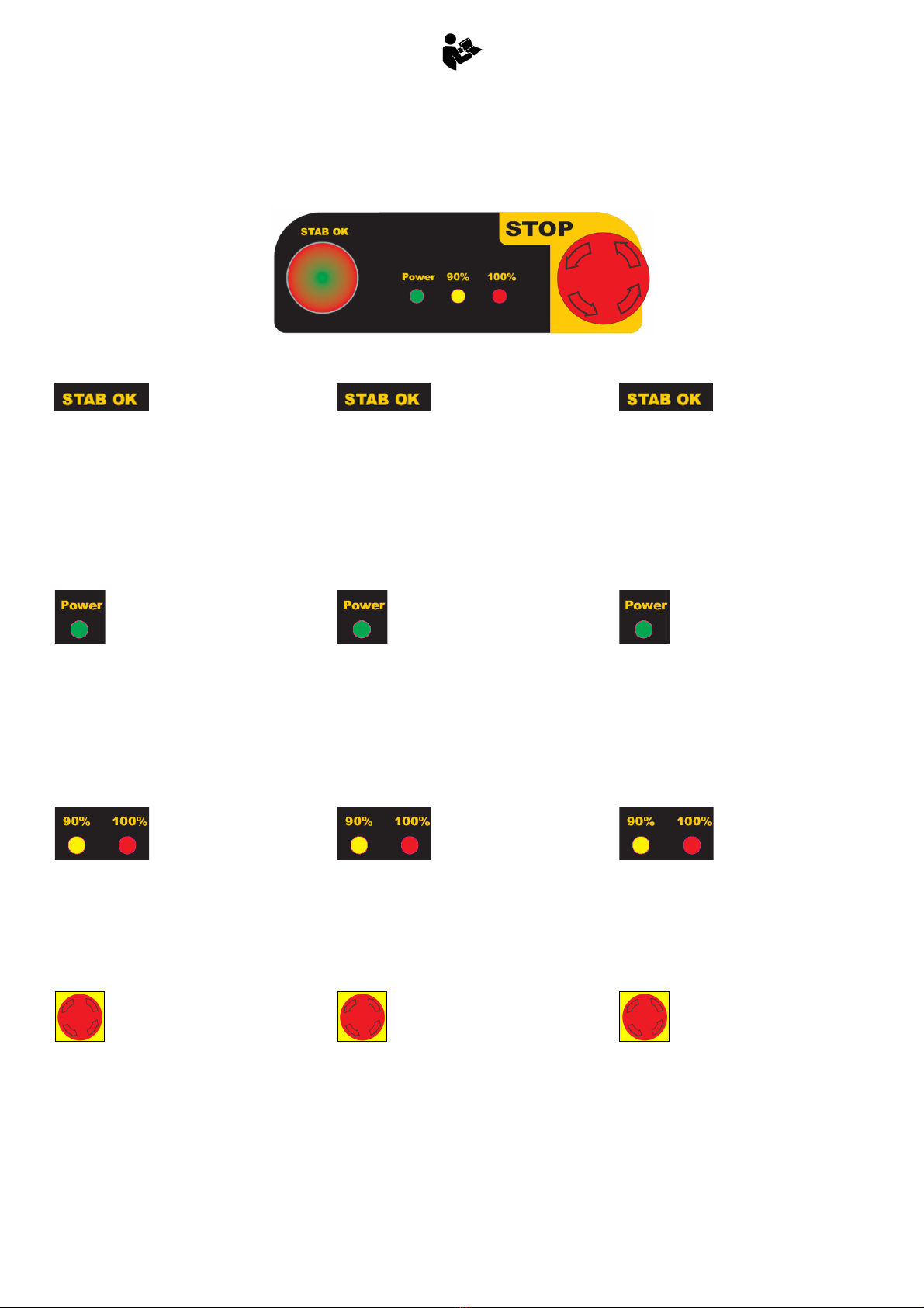
La norma armonizzata EN12999
prevede che le gru CE con limitatore di
momento siano dotate di sistemi di
controllo della stabilità (SCS) che, in
ogni situazione di lavoro, eliminino i
rischi dovuti alla perdita di stabilità.
Infatti, in base all’apertura delle aste
stabilizzatrici e al corretto piazzamento a
terra dei piedi stabilizzatori può variare
considerevolmente la capacità di carico
limite che garantisce la stabilità della
macchina:
Per un corretto utilizzo delle nuove gru
CE è necessario osservare le seguenti
indicazioni:
- Seguire le istruzioni di questo
manuale.
- Portare sempre assieme alla gru
questo manuale il quale deve essere
custodito in un luogo protetto e di facile
accesso al solo operatore.
- In caso di vendita della gru il nuovo
proprietario è tenuto a richiedere una
copia aggiornata del presente
manuale.
- In caso di danneggiamento, anche
parziale, o perdita del seguente
Manuale rivolgersi ad una officina
autorizzata.
Il presente manuale è relativo
ai soli comandi CE secondo la norma
EN12999.
PREMISE
The harmonized standard EN12999
provides that all CE cranes with moment
limiter are equipped with a stability
control system (SCS): this device should
avoid rinks due to leak of stability in
every work condition.
In fact, depending on stabilizer beams
opening and on correct feet lowering on
the ground, the load capacity that
guarantees the stability of the machine
can change very much.
For using correcly the new CE cranes
it’s necessary to observe the following
indications
- Follow the instructions in this manual.
- Always keep this manual in a safe
place with the crane so that it is
accessible to the operator at all times.
- If the crane is sold the new owner must
request an updated version of this
manual.
- Refer to an authorised assistance
centre in the event of damage to, even
partial, or loss of this manual.
This manual is for the CE
controls only according to the
standard EN12999.
VORWORT
Die harmonisierte Norm EN12999 sieht
vor, dass alle mit Momentbegrenzer
ausgerüsteten CE-Kräne mit
Stabilitätskontrollsystemen (SCS)
ausgestattet sind. Ihre Aufgabe ist es,
das Risiko von Stabilitätsverlust unter
jeder Arbeitsbedingung zu beseitigen.
Nämlich kann die Grenzhubkraft, die die
Stabilität der Maschine sicherstellt,
aufgrund der Öffnungsbreite der
Abstützstangen und der korrekten
Aufstellung der Stützfüsse auf Grund
ganz verändern.
Um die neue Kräne korrekt zu benutzen,
ist es notwendig, die folgende
Anweisungen einzuhanlten:
- Die Anweisungen dieses Handbuches
befolgen.
- Dieses Handbuch muss sich immer im
Kran befinden, damit es vom
Kranführer zu jeder Zeit eingesehen
werden kann.
- Wird der Kran weiterverkauft, muss der
neue Eigentümer eine aktualisierte
Kopie des vorliegenden Handbuchs
anfordern.
- Bei teilweiser Beschädigung oder
Verlust dieses Handbuchs wenden Sie
sich bitte an eine autorisierte
Werkstatt.
Das vorliegende Handbuch
bezieht sich nur auf den CE-
Steuerungen nach der Norm
EN12999.

S System
A
-1
A MANUALE D’USO SISTEMA S
A S-SYSTEM USER MANUAL
A BEDIENUNGSANLEITUNG S-SYSTEM

S System
A
-2
A.1 DESCRIZIONE DEL
SISTEMA S
Per avere le informazioni necessarie
per il controllo della stabilità il sistema
utilizza sensori digitali di prossimità
(proximity) e sensori analogici:
Proximity: apertura aste, piedi
stabilizzatori a terra, posizione gru
chiusa, posizione cursore
Sensori analogici (trasduttore di
pressione)
A.1.1 SENSORI PROXIMITY
I sensori digitali di prossimità (chiamati
anche proximity) sono sensori in grado
di rilevare la presenza di oggetti nelle
immediate vicinanze del "lato sensibile"
del sensore, senza che vi sia contatto
fisico.
P1-P2: piede stabilizzatore gru GIÙ
P3-P4: piede stabilizzatore suppl. giù
P5: chiusura gru
P6-P7: asta gru totalmente aperta
P8-P9: asta suppl. totalmente aperta
A.1.2 SENSORE ANALOGICO
Il rilevamento della pressione nel
cilindro che controlla il carico viene
effettuato tramite un trasduttore di
pressione, montato direttamente sulla
valvola cilindro 1° braccio.
A.1 DESCRIPTION OF S-
SYSTEM
To gather enough information for
monitoring stability, the system uses
digital proximity sensors and analog
sensors on the crane:
Proximity sensors: stabilizer beams
opening, stabilizer feet on the
ground, crane in closed position,
valve spool position
Analog sensors (pressure
transducer)
A.1.1 PROXIMITY SENSORS
The digital proximity sensors are
positioned to sense objects in the
immediate vicinity of the “sensitive side”
of the sensor without requiring physical
contact.
P1-P2: crane stabilizer foot DOWN
P3-P4: additional stabilizer foot DOWN
P5: crane in closed position
P6-P7: crane beam fully open
P8-P9: additional beam fully open
A.1.2 ANALOG SENSOR
Sensing of the pressure in the lifting
cylinder, in order to monitor the load, is
performed by a pressure transducer
mounted on the lifting cylinder valve.
A.1 BESCHREIBUNG
DES S-SYSTEMS
Das Stabilitätskontrollsystem benutzt
Daten, die es von Näherungs- und
Analogsensoren bekommt:
Näherungssensoren: Ausfahren der
Abstützstangen, Stützfüsse auf
Grund, Kran in geschlossener
Position, Steuerkolbenposition
Analogsensor (Druckgeber)
A.1.1 NÄHERUNGSSENSOR
Die Näherungsensoren (Proximity) sind
Geräte, die die Anwesenheit von
Gegenstanden in unmittelbarer Nähe
der “empflindlicher Seite“ ohne Kontakt
bemerken können.
P1-P2: Kranstüzfuss UNTEN
P3-P4: Zusatzstüzfuss UNTEN
P5: Kran in geschlossener Position
P6-P7: Kranstange ganz ausgefahren
P8-P9: Zusatzstange ganz ausgefahren
A.1.1 ANALOGSENSOR
Der Druck innerhalb des Hubzylinders
wird von einem Druckgeber auf dem
Hubzylinderventil aufgenommen.
CVS OCVS
P1 P2
P4 P3
S
P5
RB
P6 P7
P9 P8
System

S System
A
-3
A.1.3 PANNELLO DI
CONTROLLO
(spia stabilizzatori OK,
verde/rossa): La spia lampeggia
verde/rosso quando la macchina non è
ancora stabilizzata oppure se durante le
operazioni di sollevamento un piede
stabilizzatore perde il contatto col
terreno.
La spia è accesa verde quando la
macchina è stabilizzata correttamente e
tutti i piedi stabilizzatori sono a contatto
col terreno.
(spia di alimentazione,
verde): La spia è accesa quando il
quadro comandi è alimentato (sono
attivi l'elettrovalvola di emergenza e il
limitatore di momento). La pressione del
pulsante d'arresto d'emergenza toglie
l'alimentazione elettrica alla gru. La
riattivazione del pulsante di arresto
d'emergenza accende il quadro elettrico
della gru.
(spie di carico, gialla e
rossa): Le spie si accendono quando la
gru solleva rispettivamente oltre il 90%
e il 100% della portata massima.
L'accensione della spia rossa indica
l'intervento del limitatore di momento.
Pulsante STOP: Pulsante
d'arresto d'emergenza: interrompe
l'alimentazione elettrica dei quadri
comandi e blocca la gru.
A.1.3 CONTROL PANEL
(stabilizer OK light,
green/red): The light flashes green/red
when the crane is not yet stabilized or if,
during operation, a stabilizer foot loses
contact with the ground.
The light is on (green) when the
machine is stabilized correctly and all
stabilizers are in contact with the
ground.
(power light, green): The light
is on when the control panel has power
(emergency valve and moment limiter
active). Pressing the emergency stop
button turns off electrical power to the
crane. Reactivation of the emergency
stop button provides power to the
crane’s control box.
(load lights, yellow
and red): The lights turn on when the
crane’s loading surpasses 90% and
100%, respectively, of the maximum
capacity. Activation of the red light
indicates intervention by the load
limiting device.
STOP Button: Emergency
stop button: interrupts power to the
electrical box and blocks all crane
movements.
A.1.3 STEUERTAFEL
(Abstützungen OK
Kontrolleuchte, grün/rot): die
Kontrolleuchte blinkt grün/rot, wenn die
Maschine noch nicht stabilisiert ist, oder
wenn ein Stützfuss während der
Kranbewegungen den Kontakt zum
Grund verliert.
Die Kontrolleuchte leuchtet (grün), wenn
die Maschine korrekt stabilisiert ist und
wenn alle Stützfüsse den Grund
behrüren.
(Zündkontrolleuchte, grün):
Die Kontrolleuchte luechtet, wenn die
Steuertafel versorgt ist: das
Notmagnetventil und der Moment-
begrenzer sind eingeschaltet.
Wenn man die Notstopptaste gedrückt
wird, wird der Kran ausgeschaltet.
Die Wiederherstellung der Notstopp-
taste schaltet die Steuertafel ein.
(Lastkontrolleuchten,
gelb und rot): die Kontrolleuchten
leuchten, wenn die Last 90%, bzw.
100% der maximalen Hubkraft erreicht.
Wenn die rote Kontrolleuchte leuchtet,
ist der Momentbegrenzer eingeschaltet.
STOP Taste: der NOT-AUS-
Taster schaltet die elektrische
Versorgung aus und blockiert alle
Kranbewegungen.

S System
A
-4
A.2 FUNZIONAMENTO
DEL SISTEMA S
Il sistema di controllo stabilità S
permette l'utilizzo della gru solo dopo la
corretta stabilizzazione della macchina,
cioè dopo
estensione al 100% di tutte le aste
stabilizzatrici (anche quelle
supplementari se presenti)
piazzamento a terra di tutti i piedi
stabilizzatori
Il piazzamento degli stabilizzatori è
consentito solo quando la gru si trova in
posizione di riposo. Nel caso in cui
anche un solo stabilizzatore non venga
piazzato correttamente, i comandi gru
vengono bloccati.
Una volta effettuata la stabilizzazione, il
sistema permette la movimentazione
della gru in tutti i suoi movimenti.
Quando la gru è aperta il sistema
blocca tutti i comandi degli stabilizzatori:
è necessario tenere chiuse le valvole di
blocco sui cilindri stabilizzatori).
A.2 HOW THE S-
SYSTEM FUNCTIONS
The S system stability control allows
use of the crane only after the machine
is correctly stabilized, which is after:
100% extension of all stabilizer
beams (and supplementary beams,
if present)
Lowering of all stabilizer feet to the
ground
Placement of the stabilizers is only
allowed when the crane is in the rest
position. If only one stabilizer is not
correctly placed on the ground, the
crane will be stopped.
Once stabilization is complete, the
system allows the use of all crane
functions.
While the crane is open, the system will
block all stabilizer functions (it is still
necessary to keep the stabilizer lock
valves closed).
A.2 FUNKTIONEN DES
S-SYSTEMS
Das S-Stabilitätskontrollsystem erlaubt
mit dem Kran nur nach der korrekten
Stabilisierung der Maschine zu arbeiten,
das heisst nach:
100% Ausfahren aller Abstütz-
stangen (auch aller Zusatzstangen
wenn anwesend)
Senken aller Stützfüsse auf den
Boden
Die Öffnung der Abstützungen wird nur
erlaubt, wenn der Kran geschlossen ist.
Wenn nur eine Abstützung unkorrekt
geöffnet ist, werden alle Kran-
steuerungen blockiert.
Nach einer korrekten Stabilisierung,
erlaubt das System alle Kran-
bewegungen
Wenn der Kran offen ist, schaltet das
System alle Abstützsteuerungen aus: es
ist notwendig, die Abstützblockventile
geschlossen zu halten.
LS
100% 0%
RS
100%
0%
100%
0%
100% 0%
RSS
LSS
CABINA
100%
100%
100%
100%
o area non permessa
STAB OK
90%
100%
STAB OK
90%
100%
o zona non permessa
or non-permitted zone
oder unerlaubte Zone

S System
A
-5
LIMITATORE DI MOMENTO
Quando in fase di lavoro si raggiunge la
pressione massima, il sistema
interviene bloccando tutti i comandi
della gru ad eccezione del rientro delle
estensioni idrauliche.
MOMENT LIMITER
When the max working pressure is
reached, the system disables all crane
movements, except retraction of
hydraulic extensions.
MOMENTBEGRENZER
Wenn der max Druckwert erreicht wird,
deaktiviert das System alle Kran-
bewegungen außer dem Einfahren der
hydraulischen Ausschübe.
Movimenti permessi
Permitted movements
Erlaubte Bewegungen
Segnalazione carico tra 90%-100%
Warning signals: load between 90%-100%
Warnsignale: Last zwischen 90%-100%
Segnalazione carico al 100%
Warning signals: 100% load
Warnsignale: Last zu 100%
STAB OK
90%
100%
STAB OK
90%
100%

S System
A
-6
SOLLEVAMENTO DI UN PIEDE
STABILIZZATORE DA TERRA
DURANTE LE FASI DI LAVORO
Può accadere che durante la fase di
lavoro uno o più piedi stabilizzatori
possano momentaneamente distaccarsi
da terra: in questo caso, nonostante
riconosca la momentanea perdita di
contatto dello stabilizzatore, il sistema
permette di movimentare la gru.
SENSORE GRU CHIUSA
BYPASSATO A GRU ATTIVA
Se il sensore rileva che la gru è chiusa
e il trasduttore di pressione sul cilindro
1° braccio rileva una pressione
maggiore del 30% circa di quella
massima, si attivano i seguenti allarmi:
Il limitatore attiva i movimenti gru per
una durata di 5s e li disattiva per i
successivi 30s. Poi ripete il ciclo di 5s di
attivazione e di 30s di disattivazione
finché la pressione rilevata risulta
minore della percentuale impostata. In
questa condizione i movimenti
stabilizzatori sono bloccati.
SENSORE GRU CHIUSA
BYPASSATO ALL'ACCENSIONE
DELLA GRU
Se il sensore rileva la presenza del
braccio e il trasduttore di pressione
rileva una pressione maggiore del 30%
circa di quella massima, si attivano i
seguenti allarmi:
Il limitatore di momento blocca tutti i
movimenti della gru ad esclusione del
rientro delle estensioni idrauliche.
Questo comando rimane l’unico abilitato
finché la pressione rilevata risulta
minore della percentuale impostata.
LOSS OF CONTACT BETWEEN
STABILIZER FOOT AND GROUND
DURING WORKING OPERATIONS
It can happen that during working
operations one or more stabilizers
momentarily lift off the ground: in this
case, despite detecting the momentary
loss of contact between stabilizer and
ground, the system will allow continued
operation of the crane.
SENSOR FOR CLOSED CRANE
BYPASSED WITH CRANE ACTIVE
If, the sensor indicates closed crane
while the pressure transducer on 1st
boom cylinder detects a pressure more
than 30% (approx.) of the max
pressure, these alarms are active:
The moment limiter allows all functions
for 5 seconds, followed by blocking all
functions for 30 seconds. The cycle
repeats again, with 5 seconds activated
and 30 seconds deactivated, until the
1st boom cylinder pressure is again
below the limit. During this condition
stabilizer operation is blocked.
SENSOR FOR CLOSED CRANE
BYPASSED AT CRANE STARTUP
If the sensor indicates close crane while
the pressure transducer detects a
pressure greater than 30% (approx.) of
maximum, these alarms are active:
The moment limiter blocks all crane
movements except for retraction of the
hydraulic extensions. This remains the
only enabled function until the detected
pressure is below the limit.
KONTAKTVERLUST ZWISCHEN
STÜTZFUSS UND BODEN WÄHREND
DER ARBEITSOPERATIONEN
Es kann passieren, dass ein oder mehr
Stützfüsse sich vom Boden erheben: in
diesem Fall erlaubt das System alle
Kranbewegungen, obwohl es die
Kontaktverlust des Stützfuss bemerkt.
SENSOR FÜR GESCHLOSSENEN
KRAN BEI AKTIVEM KRAN
UMGANGEN
Wenn der Sensor bemerkt, dass der
Kran geschlossen ist, während der
Druckgeber auf dem 1.Auslegerzylinder
einen höheren Druck als 30% (zirka)
des Grenzdrucks erhebt, werden die
folgenden Alarme aktiviert.
Der Momentbegrenzer schaltet die
Kranbewegungen für 5s ein, dann er
schaltet sie für 30s aus. Dieser Zyklus
von Einschaltung und Ausschaltung
wird wiederholt, bis der Hubdruck
nidrieger als der Grenzdruck wird.
Bei diesem Arbeitsmodus werden die
Stützbewegungen blockiert.
SENSOR FÜR GESCHLOSSENEN
KRAN UMGANGEN BEIM STARTEN
DES KRANS
Wenn der Sensor bemerkt, dass der
Kran geschlossen ist, während der
Druckgeber einen höheren Druck als
30% zirka des Grenzdrucks erhebt,
werden die folgenden Alarme aktiviert:
Der Momentbegrenzer blockiert alle
Kranbewegungen ausser dem
Einfahren der Ausschübe. Diese
Bewegung bleibt die einzige aktive, bis
der Hubdruck nidrieger als der
eingestellte Grenzdruck wird.
STAB OK
90%
100%
STAB OK
90%
100%
STAB OK
90%
100%

S System
A
-7
A.3 CONTROLLI PRIMA
DELL’USO DELLA GRU
All’accensione, prima dell’utilizzo della
gru, l’operatore è tenuto a verificare il
corretto funzionamento dei proximity
sulle aste stabilizzatrici e del limitatore
di momento.
PROCEDURA DI CONTROLLO
- Stabilizzare la gru (vedi MAUM)
- Verificare che tutti i led dei proximity
sulle aste stabilizzatrici siano accesi.
- Sollevare il 1.braccio e portare il
cilindro di sollevamento a fine corsa.
Verificare l’intervento del limitatore di
momento: si deve accendere per un
istante la spia rossa 100% sul
pannello di controllo.
Se la verifica ha avuto esito
negativo, la gru non può essere
utilizzata: l’operatore deve chiudere
la gru in posizione di trasporto e
rivolgersi a un’officina autorizzata.
A.3 CHECKS BEFORE
OPERATING A CRANE
At every startup, before operating the
crane, the operator has to check that
the proximity sensors on the stabilizer
beams and the moment limiter function
correcly.
CHECK PROCEDURE
- Stabilize the crane
- Check that the leds of all proximity
sensors on stabilizer beams are ON.
- Raise the 1st boom opening the lifting
cylinder up to the end of stroke.
Check the correct activation of the
moment limiter: the red light (100%)
on the control panel should illuminate
for a moment.
If the check is unsuccessful,
the crane can’t be used: the operator
shall close the crane in transport
position and contact an authorised
assistance centre.
A.3 PRÜFUNGEN VOR
DEM KRANBETRIEB
Bei jeder Zündung vor dem Kranbetrieb,
muss der Kranführer überprüfen, dass
die Näherungssensoren auf den Stütz-
stangen und der Momentbegrenzer
korrekt funktionieren.
PRÜFUNGSVERFAHREN
- Den Kran stabilisieren
- Überprüfen, dass alle LED der
Näherungssensoren auf den Stütz-
stangen leuchten.
- Den 1.Ausleger heben, und das
Hubzylinder bis zum Endanschlag
öffnen. Das korrekte Ansprechen des
Momentbegrenzers überprüfen: die
rote Kontrolleuchte (100%) auf der
Steuertafel soll leuchten für einen
Augenblick.
Wenn die Prüfung einen
schlechten Ausgang genommen hat,
muss der Kranführer den Kran in
Transportposition schliessen und
sich an eine autorisierte Werkstatt
wenden.

S System
A
-8
A.4 SEGNALAZIONI DI
SOVRACCARICO
LIMITATORE DI MOMENTO
Legenda
A.4 OVERLOAD
WARNING SIGNALS
MOMENT LIMITER
Legend
A.4 WARNSIGNALE BEI
ÜBERLAST
MOMENTBEGRENZER
Zeichenerklärung
Power STAB OK 90% 100%
Allarme sonoro
Audible alarm
Akust. Alarm
Carico < 90% portata max
Load < 90% max capacity
Last < 90% max. Tragfähigkeit
Carico tra 90%-100% portata max
Load between 90%-100% max capacity
Last zwischen 90%-100% max Tragfähigkeit
Carico = 100% portata max
Load = 100% max capacity
Last = 100% max. Tragfähigkeit
Piede stabilizzatore sollevato da terra
Stabilizer foot lifted off the ground
Stützfüß vom Boden abgehoben
Sensore gru chiusa bypassato
Sensor for closed crane bypassed
Sensor für geschlossenen Kran umgangen
Simbolo
Symbol Descrizione Description Beschreibung
Luci di segnalazione spente Warning lights off Ausgeschaltete Warnleuchten
Luci di segnalazione lampeggianti Flashing warning lights Blinkende Warnleuchten
Luce lampeggiante a due colori Bi-color flashing light Zweifarbig blinkende Kontrolleuchte
Luci di segnalazione accese fisse Warning lights turned on Eingeschaltete Warnleuchten
Allarme sonoro non attivo Audible alarm deactivated Deaktivierter akustischer Alarm
Allarme sonoro attivo intermittente Intermittent audible alarm Intermittierender akustischer Alarm
Allarme sonoro attivo continuo Continuous audible alarm Kontinuierlicher akustischer Alarm

S System
A
-9
A.5 SEGNALI DI
ALLARME
Legenda
ELENCO ALLARMI STAB
OK PWR 90% 100% RISOLUZIONE PROBLEMI
Mancanza di alimentazione
al sistema
- Verificare il fusibile sulla linea d’alimentazione (F01-5A)
- Verificare che non sia premuto il pulsante d’arresto
d’emergenza
- Verificare presenza di alimentazione sul cavo di alimentazione
Ingresso trasduttore di
pressione scollegato
- Verificare il trasduttore di pressione
- Verificare il cavo del trasduttore di pressione
- Montare una resistenza 2kOhm sul connettore del trasduttore
di pressione (X3)
Ingresso trasduttore di
pressione in corto circuito
1
2
3
- Verificare il trasduttore di pressione
- Verificare il cavo del trasduttore di pressione
- Montare una resistenza 2kOhm sul connettore del trasduttore
di pressione (X3)
Scheda elettronica non
programmata
Ritarare il limitatore di momento
Switch rientro estensioni
idrauliche aperto in
accensione
- Verificare lo switch sul distributore “L.S. Estensioni IN”
- Verificare il cavo switch “L.S. Estensioni IN”
- Verificare presenza di tensione sul PIN 3, connettore X2
- collegare PIN3 con PIN4, connettore X2, per simulare la
presenza dello switch
Switch centralizzato aperto
in accensione
- Verificare lo switch centralizzato e il funzionamento dei
leveraggi sul distributore
- Verificare il cavo collegato allo switch centtralizzato
- collegare PIN 1 con PIN2, connettore X2, per simulare la
presenza dello switch
YVH1 in cortocircuito Manca la segnalazione
Sistema attiva una logica di protezione
- Verificare lo stato del cablaggio collegato all’elettrovalvola di
emergenza
- Verificare il solenoide
Switch movimentazione
stabilizzatori aperto in
accensione
- Verificare lo switch sul distributore “controllo stab.”
- Verificare il cavo switch collegato al “controllo stab.”
- Verificare presenza di tensione sul PIN 1, connettore X5
- collegare PIN1 con PIN4, connettore X5, per simulare la
presenza dello switch
Switch rientro estensioni,
switch centralizzato e
proximity leva stabilizzatori
tutti aperti in accensione
- Verifica dei sensori
- Verifica cablaggio
YVH1 alta incongruente
con logica di controllo
- Verificare lo stato del cablaggio collegato all’elettrovalvola di
emergenza
Segnale di gru chiusa con
carico P1 > P1max / 10
(circa)
- Verificare lo stato del sensore gru chiusa (la luce sul sensore
deve essere spenta con gru aperta, la luce sul sensore deve
essere accesa a gru chiusa)
- Scollegare il sensore “Gru chiusa” per simulare la gru aperta
- Verificare lo stato del cavo collegato al sensore “Gru chiusa”
Spia spenta
Spia lampeggiante
Spia accesa
Spia lampeggiante a due colori
1... 2... 3
Sequenza di accensione

S System
A
-10
A.5 ALARM SIGNALS
Legend
ALARM DESCRIPTION STAB
OK PWR 90% 100% PROBLEM RESOLUTION
No power to system
- Check the fuse on the power supply cable (F01-5A)
- Ensure the emergency stop button is not pressed
- Check for power on the supply cable
Pressure transducer
disconnected
- Check the pressure transducer
- Check the pressure transducer’s cable
- Connect a 2Kohm resistor across connector X3 to simulate the
presence of the transducer
Pressure transducer input
short-circuited
1
2
3
- Check the pressure transducer
- Check the pressure transducer’s cable
- Connect a 2Kohm resistor across connector X3 to simulate the
presence of the transducer
Electronic board not
programmed
- Recalibrate the moment limiter
Extension retract switch
open during system startup
- Check switch “L.S. Extensioni IN” on the control valve
- Check the cable for switch “L.S. Extensioni IN”
- Check for voltage on PIN 3, connector X2
- Connect PIN3 to PIN4, connector X2, to simulate the presence
of the switch
Central switch open during
system startup
- Check the central switch and the function of the levers on the
control valve
- Check the cable to the central switch
- Connect PIN1 to PIN2 on connector X2 to simulate the
presence of the switch
YVH1 short-circuited No signals
System protection mode active
- Check the condition of the cable connected to the emergency
valve
- Check the emergency valve solenoid
Stabilizer movement switch
open during system startup
- Check switch “controllo stab.” on the control valve
- Check the cable to switch “controllo stab.”
- Check for voltage on PIN1, connector X5
- Connect PIN1 to PIN4, connector X5, to simulate the presence
of the switch
Extension retract switch,
central switch, and
stabilizer movement switch
all open during system
startup
- Check sensors
- Check cables
YVH1 powered (high)
contrary to control system
logic
- Check the condition of the cable connected to the emergency
valve
Signal to indicate closed
crane with load P1 >
P1max / 10 (approximate)
- Check the condition of the sensor for closed crane (the light on
the sensor should be off with crane open, on with crane
closed)
- Disconnect sensor “Gru chiusa” to simulate crane open
- Check the condition of the cable for sensor “Gru chiusa”
Light off
Flashing light
Light on
Bi-color flashing light
1... 2... 3
Sequence of illumination

S System
A
-11
A.5 ALARMSIGNALE
Legende
BESCHREIBUNG STAB
OK PWR 90% 100% LÖSUNG
Keine Versorgung
- Die Sicherung auf der Versorgungslinie überprüfen (F01-5A)
- Überprüfen, ob die Notstopptaste gedrückt ist
- Den Strom in der Versorgungslinie überprüfen
Druckgeber nicht
verbunden
- Den Druckgeber überprüfen
- Das Kabel des Druckgebers überprüfen
- Einen Widerstand von 2kOhm auf dem Verbinder (X3) des
Druckgebers bestücken
Druckgebereingabe auf
Kurzschluss
1
2
3
- Den Druckgeber überprüfen
- Das Kabel des Druckgebers überprüfen
- Einen Widerstand von 2kOhm auf dem Verbinder (X3) des
Druckgebers bestücken
Elektrokarte nicht
programmiert
Den Momentbegrenzer wiedereichen
Switch von Einfahren der
Ausschübe geöffnet
während der Zündung des
Systems
- Den Switch “L.S. Extension IN” auf Steuerventil überprüfen
- Das Kabel für Switch “L.S. Extension IN” überprüfen
- Spannung auf PIN 3, Verbinder X2, überprüfen
- PIN3 mit PIN4 auf Verbinder X2 verbinden, um die
Anwesenheit des Switch zu simulieren
Zentralswitch geöffnet
während der Zündung des
Systems
- Den Zentralswitch und die Funktion der Hebel auf dem
Steuerventil überprüfen
- Das Kabel zum Zentralswitch überprüfen
- PIN1 mit PIN2 auf Verbinder X2 verbinden, um die
Anwesenheit des Switch zu simulieren
YVH1 auf Kurzschluss Kein Signal
Schutzmodus des Systems aktiviert
- Den Zustand des mit dem Notmagnetventil verbundenen Kabel
überprüfen
- Den Notmagnet überprüfen
Switch von
Abstzübewegung geöffnet
während der Zündung des
Systems
- Den Switch “controllo stab.” auf Steuerventil überprüfen
- Das Kabel des Switch “controllo stab.” überprüfen
- Die Anwesenheit der Spannung auf PIN 1, Verbinder X5
überprüfen
- PIN1 mit PIN4 auf Verbinder X5 verbinden, um die
Anwesenheit des Switch zu simulieren
Switches von Einfahren der
Ausschübe, Zentralswitch
und Switch von
Abstzübewegung geöffnet
während der Zündung des
Systems
- Die Sensoren überprüfen
- Die Verkabelung überprüfen
YVH1 versorgt (hoch) im
Gegensatz zur Logik des
Kontrollsystems
- Den Zustand der mit dem Notmagnetventil verbundenen
Verkabelung überprüfen
Signal von “geschlossenem
Kran” mit Last P1 > P1max
/ 10 (zirka)
- Den Zustand des Sensors von geschlossenem Kran überprüfen
(die Leuchte auf dem Sensor muss bei offenem Kran
ausgelöscht sein, sie muss bei geschlossenem Kran leuchtend
sein)
- Den Sensor “Gru chiusa” zerlegen, um den geöffneten Kran zu
simulieren
- Den Zustand des mit dem Sensor “Gru chiusa” verbundenen
Kabels überprüfen
Ausgeschaltete Kontrolleuchte
Blinkende Kontrolleuchte
Leuchtende Kontrolleuchte
Zweifarbig blinkende Kontrolleuchte
1... 2... 3
Beleuchtungsfolge

S System
A
-12
A.6 SCHEMI ELETTRICI
Schema generale
A.6 ELECTRICAL
SCHEMATICS
Complete schematic
A.6 STROMKREIS-
SCHEMA
Allgemeines Schema
Cod: 1010121
123
JP1 7
JP1 1
JP1 4
12
3
4
JP1 6
JP1 3
Q01
JP1 5
JP1 9
654321
JP2 11
JP2 1
JP2 2
JP2 10
12
JP2 4
JP2 7
2
JP2 6
YVH1
com
NC
com
NC
bar
13
12
1
32
Boom in L.S.
Centralized L.S.
Pressuretransducer
Main valve
Stab DWN CVS
Stab control
1
2
M
+
-
324
F01
5A
2
13
213
213
2
13
JP2 5
JP1 12
MAIN DASH BOARD
34
2
1
JP3 4
JP3 8
JP3 9
Link
X9
X8
X7
S01
S02
S03
S05
S06
S07
S08
S09
X10
X1 X2 X3
X4
X11
1
32
1
32
1
32
1
32
1
34
Load Cell
X6
Power Supply
Crane Recovered
S04
X101
X103
Beam open CVS Beam open OCVS
Stab DWN OCVS
213
X5

S System
A
-13
Schema elettrico gru con
Power Pack
Lo schema elettrico del
veicolo è puramente indicativo.
Electrical schematic for crane
with Power Pack
The schematic of the
vehicle’s electrical system is purely
indicative.
Stromkreisschema für Kran
mit Power Pack
Das Stromkreisschema des
Fahrzeuges ist nur weisend.
+
-
BK 50
RD 50
M
M01
RD 50
RD 50
BK 50
YL/GN 1 YL/GN 1
BR 1
BR 1
BR 1
BR 1
RD 50 BK 50
BU 1
YL/GN 1
BR 1
8.5 +/- 0.5 Nm
RELE AVV MOT
SHT 2 2A
SHT 2 2E
SHT 2 2F
G01
SHT 4 2A
PWR
VEHICLE'S ELECTRIC WIRING
CHASSIS
ELECTRIC
ELECTRIC MOTOR
Tightening torque
MOTOR
Cod: 1010121-P1
This manual suits for next models
1
Table of contents