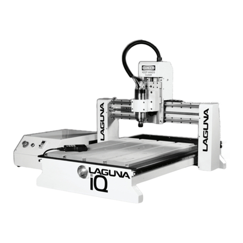
Laguna Tools CNC Swift Series User manual

CNC Swift Series
with WinCNC Manual
LAGUNA TOOLS
2072 Alton Parkway
Irvine, California 92606
Ph: 800.234.1976
www.lagunatools.com
MCNC Swift 48 X 96-0233
MCNC Swift 48 X 48 1000-0233
© 2017, Laguna Tools, Inc. LAGUNA® and the LAGUNA Logo® are the registered trademarks of Laguna Tools, Inc. All rights reserved.
Model Numbers:

Limited Warranty
New machines and accessories sold by Laguna Tools carry a one-year warranty
effective from the date of shipping. Machines sold through dealers must be registered
with Laguna Tools within 30 days of purchase to be covered by this warranty. Laguna
Tools guarantees all new machines and accessories sold to be free of manufacturers’
defective workmanship, parts and materials. We will repair or replace, without charge,
any parts determined by Laguna Tools, Inc. to be a manufacturer’s defect. We require
that the defective item/part be returned to Laguna Tools with the complaint. Any
machines returned to Laguna Tools must be returned with packaging in the same
manner in which it was received. If a part or blade is being returned it must have
adequate packaging to ensure no damage is received during shipping. In the event the
item/part is determined to be damaged due to lack of maintenance, cleaning or
misuse/abuse, the customer will be responsible for the cost to replace the item/part,
plus all related shipping charges. This limited warranty does not apply to natural
disasters, acts of terrorism, normal wear and tear, product failure due to lack of
maintenance or cleaning, damage caused by accident, neglect, lack of or inadequate
dust collection, misuse/abuse or damage caused where repair or alterations have been
made or attempted by others.
Laguna Tools, Inc. is not responsible for additional tools or modifications sold or
performed (other than from/by Laguna Tools, Inc.) on any Laguna Tools, Inc.
machine. Warranty maybe voided upon the addition of such described tools and/or
modifications, determined on a case-by-case basis.
Software purchased through Laguna Tools Inc. is not covered under this warranty
and all technical support must be managed through the software provider. Software is
non-refundable.
Normal user alignment, adjustment, tuning and machine settings are not covered by
this warranty. It is the responsibility of the user to understand basic machinery
operation, settings and procedures and to properly maintain the equipment in
accordance with the standards provided by the manufacturer.
Parts, under warranty, are shipped at Laguna Tools, Inc.’s cost either by common
carrier, FEDEX ground service or a similar method. Technical support to install
replacement parts is primarily provided by phone, fax, e-mail or Laguna Tools
Customer Support Website. The labor required to install replacement parts is the
responsibility of the user.
Laguna Tools is not responsible for damage or loss caused by a freight company or
other circumstances not in our control. All claims for loss or damaged goods must be
notified to Laguna Tools within twenty-four hours of delivery. Please contact our
Customer Service Department for more information.
Only new machines sold to the original owner are covered by this warranty.
For warranty repair information, call 1-800-332-4094.

LAGUNA TOOLS 3
TABLE OF CONTENTS
General Informaon ............................................................................................................................................... 5
Safety Rules............................................................................................................................................................................................ 5
Noise Emission ....................................................................................................................................................................................... 6
Receiving your machine ......................................................................................................................................................................... 6
Cauonary Statement............................................................................................................................................................................ 6
Introducon to the CNC machines ......................................................................................................................... 7
Parts of the CNC Machine...................................................................................................................................................................... 7
PC Components...................................................................................................................................................................................... 8
Assembly and Setup................................................................................................................................................ 8
Where to locate your Machine .............................................................................................................................................................. 8
Unpacking the Machine ......................................................................................................................................................................... 8
Seng up the Electrical Cabinet............................................................................................................................................................ 9
Connecng Power.................................................................................................................................................................................. 9
Fing the Dust Hose ........................................................................................................................................................................... 10
Spindle Cooling System........................................................................................................................................................................ 10
Control Panel Descripon ..................................................................................................................................... 12
Controller Interface Descripon ........................................................................................................................... 13
Screen Display Overview...................................................................................................................................................................... 13
Menu Bar ............................................................................................................................................................................................. 13
Tool Bar................................................................................................................................................................................................ 16
Axis Window ........................................................................................................................................................................................ 17
Buon Funcons.................................................................................................................................................................................. 17
Transit Speed Buons.......................................................................................................................................................................... 18
INPUT INDICATORS .............................................................................................................................................................................. 18
Basic Machine Operaons .................................................................................................................................... 18

LAGUNATOOLS4
TurningontheMachine.......................................................................................................................................................................18
ShuttingDowntheMachine................................................................................................................................................................19
EmergencyStopOptions......................................................................................................................................................................19
HomingtheMachine...........................................................................................................................................................................20
FittingaRoutingBit.............................................................................................................................................................................20
SpindleOperation................................................................................................................................................................................21
MeasuringToolLength(TouchTopButton)........................................................................................................................................22
SettingToolLengthOffset(Meas.ZButton).......................................................................................................................................23
FromAspiretoCuttingTutorial............................................................................................................................24
3DScanningGuide................................................................................................................................................26
Edge/OutlineScanningGuide...............................................................................................................................29
MaintenanceRecommendations..........................................................................................................................32
TroubleShooting...................................................................................................................................................33
Machinewillnotstart..........................................................................................................................................................................33
Machinewillnotstop..........................................................................................................................................................................33
Motortriestostartbutwillnotturn...................................................................................................................................................34
MotorOverheats.................................................................................................................................................................................34
Squeakingnoise...................................................................................................................................................................................34
Spindleslowsdownduringacut.........................................................................................................................................................34
Machinevibrates.................................................................................................................................................................................34
KeyboardHotkeys.................................................................................................................................................34
CommandReference............................................................................................................................................36
G‐Codes................................................................................................................................................................................................36
L‐Codes.................................................................................................................................................................................................40
M‐Codes...............................................................................................................................................................................................49
MessagesandErrorCodes...................................................................................................................................................................51
Specifications........................................................................................................................................................54

LAGUNA TOOLS 5
GENERAL INFORMATION
SAFETY RULES
As with all machinery there are certain hazards involved with the operaon and use of this machine.
Using it with cauon will considerably lessen the possibility of personal injury. However, if normal
safety precauons are overlooked or ignored, personal injury to the operator may result. If you have
any quesons relave to the installaon and operaon of this machine, do not use the equipment unl
you have contacted your supplying distributor.
Read carefully before operang the machine.
•Keep the working area clean and be sure adequate lighng is available.
•Do not wear loose clothing, gloves, bracelets, necklaces or ornaments.
•Wear face, eye, respiratory and body protecon devices as indicated for the operaon or
environment.
•Before using, be sure that the power is disconnected from the machine before tools are serviced or
an aachment is to be fied or removed.
•Never leave the machine with the power on.
•Do not use dull, gummy or cracked cung tools.
•Be sure that the keys and adjusng wrenches have been removed and all the nuts and bolts are
secured.

LAGUNA TOOLS 6
NOISE EMISSION
Notes concerning noise emission:
There is a relaonship between noise level and exposure mes but it is not precise enough to
determine the need for supplementary precauons. The factors affecng the true level of exposure to
operators are clearly the amount of me exposed, the characteriscs of the working environment
other sources of dust and noise, etc. For example,the locaon of adjacent machines in other words the
level of ambient noise. It is also possible that exposure level limits will vary from country to country.
RECEIVING YOUR MACHINE
Note. It is probable that your machine will be delivered by a third party. Before you unpack your new
machine,you will need to first inspect the packing, invoice, and shipping documents, supplied by the
driver. Insure that there is no visible damage to the packing, or the machine. Youneed to do this prior
to the driver leaving. All damage must be noted on the deliverydocuments and signed by you, and the
delivery driver. Youmust then contact the seller [Laguna Tools] within 24 hours.
CAUTIONARY STATEMENT
There is danger associated with the use of any machine. Injury is frequently caused by lack of
knowledge or familiarity. Use this machine with respect. If normal safety precauons are overlooked or
ignored, serious personal injury mayoccur. As the CNC is under the control of the onboard machine
controller, it is important that you are clear of the cuer when operang the machine.

LAGUNATOOLS7
INTRODUCTIONTOTHECNCMACHINES
TheCNCisdesignedtogiveyouyearsofsafeservice.Readthisowner’smanualinitsentiretybefore
assemblyoruse.
TheadvantageoftheCNCmachineisthatitcan,inmostcases,fullymachinethecompletejobwithout
itbeingremovedfromthetablesothatyouhavefinishedpartsofhighaccuracythataretotally
repeatable.
Iftherelevantsoftwareispurchasedandinstalled,itcanalsoproduceintricatecarvings.Nestingisalso
avaluablefeatureofCNCmachiningthatsavesonwasteandcosts.Itispossibletoreducetheamount
ofdifferentmachinesintheshopastheCNCwillperformamultitudeoffunctionsandmeettheneeds
forcabinetmakersandseriouswoodworkers.
PARTSOFTHECNCMACHINE
1. Bed‐Thebedofthemachineconsistsofaheavysteelframeanda“T‐Slot”Table.The“T”slotsare
usedtoclampthejoborfixturestothebed.
2. Gantry‐Thegantrystraddlesthebedandcarriestherouterspindlemotionsystem.Itismoved
alongthelengthofthebedbyaprecisionpiniongearsystemthatiscontrolledbythemachine
controller.
3. RouterSpindle‐Therouter
spindleismovedalongthegantry
byaprecisionballscrewsystem
thatiscontrolledbythemachine
controller.
4. Frame‐Theframeisaheavy
weldedconstructionthat
supportsalltheotherpartsof
themachine.
5. Electricalcontrolbox‐Theelectrical
controlboxislocatedonthesideofthemachineinadustfreeenclosure.
6. Caterpillartrack‐Thecaterpillartrackrunsalongthesideofthemachineinatroughandcarries
alltheelectricalcablesandthespindlecoolingtubes.
Figure1.FrontviewofamodelSwift4x8

LAGUNATOOLS8
7. Waterpump‐Thewaterpumpprovidescoolantfortherouterspindlemotor.Runningtherouter
spindlewithoutthecoolingpumprunningcanleadtospindlebearingfailure.
PCCOMPONENTS
Therearecircuitboardsthathavebeeninstalledintothe
PC'stower.IfthePCistobereplacedthecardsmustbe
re‐installedintothenewPCtower.TheWinCNCsoftware
mustthenbere‐installed.
ASSEMBLYANDSETUP
WHERETOLOCATEYOURMACHINE
Beforeyouunpackyourmachine,selecttheareawhereyouwilluseyourmachine.Therearenohardandfast
rulesforitslocation,but,hereareafewguidelines.
Thereshouldbeanareaaroundthemachinesuitableforthelengthofwoodthatyouwillbe
machining.
Adequatelighting.Thebetterthelighting,themoreaccurateandsafelyyouwillbeabletowork.
Solidfloor.Youshouldselectasolidflatfloor,preferablymadeofconcreteorsomethingsimilar.
Closetopowersourceanddustcollection.
UNPACKINGTHEMACHINE
1. Tounpackyourmachine,youwillneedtinsnips,aknifeandawrench.
2. Usingthetinsnips,cutthebandingthatissecuringthemachinetothepallet[iffitted].
WARNING:EXTREMECAUTIONMUSTBEUSEDBECAUSE
THEBANDINGWILLSPRINGANDCOULDCAUSEINJURY.
3. RemovetheboxfromtheCNCmachineiffittedandanyotherpackagingmaterial.Theparts
orderedwiththemachinewillbepackedonorinsidethemachine.Note.Themachineisheavy,
andifyouhaveanydoubtaboutthedescribedprocedure,seekprofessionalassistance.Donot
attemptanyprocedurethatyoufeelisunsafe,orthatyoudonothavethephysicalcapabilityof
achieving.
4. Useaforkliftwithsufficientliftingcapacityandforksthatarelongenoughtoreachthecomplete
widthofthemachine.
5. Removethesecuringboltsthatattachthemachinetothepallet[iffitted].
Figure2.PCTowershowinginternalPCIcards

LAGUNATOOLS9
6. Approachingthemachinefromtheside,liftthemachineontheframetakingcarethatthereareno
cablesorpipesintheareaoftheforks.
7. Movethemachinetotherequiredpositionandlowergentlytothefloor.
8. Levelthemachinesothatallthesupportingfeetaretakingtheweightofthemachineandno
rockingistakingplace.
SETTINGUPTHEELECTRICALCABINET
1. Positiontheelectricalcabinetsothatitisperpendicularto
themachine.Seefigure3.
2. Adjustthefeetonthelowershelflegsuntiltheelectrical
cabinetisstable.
3. Mountthemonitoronthetopofthecabinet.Hardwareto
mountthemonitorincludesanM8bolt,wingnut,and
washer.Seefigure6.
4. PlacethePConthelowershelfonthebacksideofthe
machine.Seefigure4.
4.1 HavethefrontofthePCfacethemachinesothatthe
computer’sfanfacesawayfromthemachine.Thisistohelp
reducetheamountofdustthatwillenterthePC’svents.
4.2 LeaveagapbetweenthePC’sventsandthebackpanelof
themachine.ThiswillpreventthePCfromoverheating.
5. ConnectPCIcablestoPC.Cablesarelabeled.Note:Themachine
willmalfunctionifthePCIcablesareconnectedincorrectly.
6. RoutepowertothemachineforthePC.
CONNECTINGPOWER
Figure3.Electricalcabinetpositioned
perpendiculartothemachine
Figure4.PCtowerpositioningand
monitormounting
Figure6.Monitormountinghardware
Figure5.PCIcableconnections

LAGUNATOOLS10
Themachinerequires220Velectricalpowerconnectedtotheprimarypowerswitch
locatedonthefrontofthecabinet.
WARNING–Contactanelectricianifthereisanyuncertaintyabouthowto
properlyconnectyourmachinetopower.
1. Connect220Vtotheprimaryswitch.
2. Routepowersupplythroughthesideopeningsontheelectricalcabinet.
FITTINGTHEDUSTHOSE
1. Fitthedusthosetothedustshroudandsecure
withtheclamp.Ensurethatitistightasitisvery
inconvenienttohaveitfalloffduringproduction.
2. Fittheshroudtotherouterhead.Adjustthe
shroudsothatthebrushesareevenwiththetipof
therouterbitsthatyouwillbeusing.Ifitistoolow
thebrushesmaydragonthejobbeingcutand
couldbecutbytherouterbit.Ifitistoohighandisnotincontactwiththejob,suctionmaynotbe
optimal.Onceadjusted,clampwiththeclamping
Allenscrew.
3. Feedthedusthosethroughthedusthosesupport.
4. Fitthedusthoseadaptortotheendofthedusthose
andsecurewiththeclamp.Theadaptorallowsa4”
hosetobeconnectedtothemachine.
5. Theheadofthemachinewillmoveacrossthecompletetableandthedusthosewillfollowthe
head.Ifthereisinsufficientslack,thehosemaybreakordamagethedustshroud.Itissuggested
thatthehosebesuspendedfromtheceilingofyourshopwithsufficientslacksothatitwillnot
restrictmovement.Itwillalsobeoutofthewayandnotcauseatrippinghazard.
SPINDLECOOLINGSYSTEM
Figure7.Powersupply
connections
Figure8.Dustshroudanddusthosesetup

LAGUNATOOLS11
1. Therearetwowatertubesthatcomeoutofthecaterpillartrack.Theseareusedtoprovidecooling
fortheliquid‐cooledrouterspindle.
Note:Neverrunthemotorwithoutthecoolingbeingconnectedorthemotorcouldbedamaged.
2. Connectonewatertubetothewaterpumpandplacetheotherinthewatercontainerforthe
returnwater.
3. Itisnotimportantwhichpipeisusedasthereturn.
4. Fitthe90degreeconnectortothepump.
5. Connectoneofthepipestothewaterpumpbypushing
intothe90degreeconnector.Lightlypullonthepipeto
ensurethatitisconnectedcorrectly.
6. Fillacontainerabout¾fullwithcleanwater.
Note.Youwillneedtoprovideacoolanttankwitha
minimumcapacityof5gallons.Iftheshoptemperatureishigh,thetanksizewillhavetobe
larger.Ifyourshopislikelytobesubjecttofreezingtemperatures,antifreezemustbeaddedto
thecoolingwater.
7. Lowerthewaterpumpintothecontainerensuringthatitisthe
correctwayup[waterinletlowest]andplacethewaterreturnpipe
intothecontainer.
8. Thelogicalpositionforthewatercontainerisjustbehindthe
controlboxclosetothecaterpillartrack.Ensurethatitiscloseto
themachineasyoudonotwanttoaccidentallykickthecontainer
andspillthewater.
9. Oncetheassemblyiscompleteandthewaterpumpelectricalconnectionhasbeenmade,plugthe
pumpintothemachinewaterpumpsocketandthenliftthewaterreturnpipeupandcheckthat
thewaterisflowing.
10.Placethelidontothecontainertokeepdustanddirtoutofthecontainer.Checkthecontainer
periodicallyasthewaterwillevaporate.
Figure9.Waterpumpincoolantreservoir
Figure10.Waterpumppowersupply

LAGUNATOOLS12
Note.Ifthespindleisrunwithoutcoolingthenitcouldbedamagedandfail.
CONTROLPANELDESCRIPTION
Thissectiondescribesthefunctionsofthecontrolslocatedontheelectricalcabinet.
Figure11.Controlpaneloverview
1. Whiteindicatorlight
1.1 ON–Machinehascontrolpowerandisinthereadystate.
1.2 OFF–Themachinedoesnothavecontrolpower.
2. Redindicatorlight
2.1ON–Primarypowersupplyison,butthemachineisnotpoweredON.
2.2OFF–Machinesprimaryswitchisintheoffposition.
3. EmergencyStopSwitch
3.1ON–Machinewillceaseexecutingcommands.Ifthespindleis“ON”thespindlewillpower
down.
3.2OFF–Machineisfullyoperational.
4. ONbutton–Startsthemachine.AfterpressingtheONbuttonthemachinewillbefullyfunctional
5. GREENindicatorlight
5.1ON–WaterpumpisON.
5.2OFF–WaterpumpisOFF.
6. WaterpumpON/OFFswitch
6.1OneindicatesswitchisON,greenlightwillbeON.
6.2ZeroindicatesswitchisOFF,greenlightwillbeOFF.
7. KeyLock–MustbeintheONpositioninordertostartthemachine.

LAGUNATOOLS13
8. VariableFrequencyDrive(VFD)controller–Servesasfeedbackfromthespindle.Itisnotnecessary
tooperatethespindlefromtheVFD.VisittheDeltaElectronicswebsiteformoreinformationon
theVFDcontroller.
CONTROLLERINTERFACEDESCRIPTION
Thissectionbrieflyexplainsallthefeaturesofthecontrollerinterface.
SCREENDISPLAYOVERVIEW
MENUBAR
ThemenubarcontainsmanyofthemainfeaturesoftheWinCNCsoftware.Itisbrokendownintoseveral
generalizedsections,asshownbelow.Themenubarselectionsaredescribedinthefollowingpages.Ifamenu
optionhasashortcutkey,theshortcutkeycombinationislistedinparenthesis()afterthenameofthemenu
option.
1. FileMenu

LAGUNATOOLS14
1.1. Open(CTRL+O)‐Opensafile.
1.2. Edit(CTRL+E)‐Openstheeditor.Ifafilenameisinthecommandline,theeditoropensthatfile.
1.3. Simulate(CTRL+S)‐Simulatesafilerunningtocheckforerrorsandestimateruntime.
1.4. View(CTRL+V)‐Viewsafileintheviewerwindow.
1.5. Restart(CTRL+R)‐Opensthefilerestartdialogboxtorestartafile.
1.6. CreateHomeFile(CTRL+H)‐Createsahomefileatthecurrentmachineposition.
1.7. Import
1.7.1. Import=>DXF‐AllowstheusertoimportDXF(DrawingExchangeFormat)file.
1.7.2. Import=>HPGL‐AllowstheusertoimportHPGL(Hewlett‐PackardGraphicsLanguage)file.
Note:TheDXFandHPGLimportfeatureisintendedforcuttingsimpledesigns.WinCNCdoes
notcompensatefortooldiameterwhenconvertingthesefiles.Formorecomplicateddesign,
whereintelligenttoolpathingisimportant,pleaseuseacompatibleCAD/CAMprogram.
1.8. Digitize
1.8.1. Digitize=>Manual‐Enable/DisabletheManualDigitizingToolbar.
1.8.2. Digitize=>Automatic‐Automaticdigitizing(L802,L803).
1.8.3. Digitize=>Frame‐SkeletalDigitizing(L810).Thisscanningmethodscansacenterlineorspine,
andhorizontallinesorribsoftheobject.
1.8.4. Digitize=>Outline‐Createsanoutlinetracearoundanobject.
1.8.5. Digitize=>Laser=>RunScan‐Opensthelaserdigitizationdialogboxtosetuplaserscanning
parameters.
1.8.6. Digitize=>Laser=>ReprocessData‐Opensadatafilefromapreviouslaserscanusedtore‐
generatea3Dobjectwithdifferentfilteringoptionstoimprovethequalityofthe3Dobject.
1.9. Exit‐ClosesWinCNC.
2. ConfigurationMenu
2.1. D/ACalibration‐CalibrationSettingsforD/A(Digitalto
Analog)spindlespeedcontrol.
3. SettingsMenu
3.1. Positions‐Opensthepositionsdialogboxwithoptionsto
viewandeditstoredpositions.(Ex:G53P#tocallpositionin
G‐Code)
3.2. HomePositions‐Opensthepositionsdialogboxwithoptions
toviewandeditstoredhomepositions.(Ex:G0H#tocall
homepos.)
3.3. ToolPositions‐Opensthetoolpositionsdialogboxwithoptions
toviewandeditstoredtoolpositionsforusewithautomatictoolchangers.(Thisrequiresan
additionalsoftwarefeaturetobeenabled)
3.4. ToolLibrary‐Editsandviewsthedefinedtoollibrary.
3.5. LocalCoordinates‐ViewXYZcoordinates.
Figure12.Positionswindowexplanation

LAGUNATOOLS15
4. ViewMenu
4.1. Resolution‐Viewscurrentresolutionsettingsforeachaxis.
4.2. Acceleration‐Viewscurrentaccelerationsettingsforeachaxis.
4.3. Limits‐Viewscurrentlimitsettingsforeachaxis.
4.4. Inputs‐Viewsreal‐timeinputstates.
4.5. Outputs‐Viewsreal‐timeoutputstates.
4.6. Toolbars‐Enable/Disablethemaintoolbar.
4.6.1. Toolbars=>Size‐Changetoolbarfromsmalltolarge.
4.7. RefreshView(F5)‐Refreshesthescreen.
4.8. ClearScreen(CTRL+C)‐Clearsthemessagedisplaywindow.
5. OptionsMenu
5.1. SoftLimits(CTRL+L)‐Enable/Disablethesoftwarelimits.
5.2. Keyboard(CTRL+K)‐Enable/Disablethekeyboardtransit/jogcontrolusedtomovethemachinewith
thekeyboard.
5.3. Buttons‐Usedtocustomizebuttons.
5.4. AutoRepeat‐Autopopulatethecommandlinewiththelastcommandexecuted.
5.5. AutoRun‐Enable/Disabletheautorunfeature.
5.6. AutoPreview‐Enable/Disabletheautopreviewfeature.
5.7. SingleStep(CTRL+P)‐Enable/DisablesinglelineexecutionofG‐Codefiles.
6. UnitsMenu
6.1. Inches‐Setstheunitofmeasuretoinches.
6.2. Centimeters‐Setstheunitofmeasuretocentimeters.
6.3. Millimeters‐Setstheunitofmeasuretomillimeters.
7. TransitMenu
7.1. Slow(F2)‐Setsthetransitspeedtoslow.
7.2. Medium(F3)‐Setsthetransitspeedtomedium.
7.3. Fast(F4)‐Setsthetransitspeedtofast.
8. JogMenu
8.1. 0.001(F6)‐Setsjogincrementto0.001unitsofmeasure.
8.2. 0.01(F7)‐Setsthejogincrementto0.01unitsofmeasure.
8.3. 0.1(F8)‐Setsthejogincrementto0.1unitsofmeasure.
8.4. 1(F9)‐Setsthejogincrementto1unitofmeasure.
8.5. Custom(F10)‐Setsacustomjogincrement.
9. HelpMenu
9.1. HelpTopics(F1)‐Activatesthein‐programhelpmenu.
9.2. UpdateProgram‐Openstheupdateutility.
9.3. About‐DisplaystheWinCNC“About”boxwhichcontainsimportantinformationaboutyourspecific
softwarepackage.TheAboutboxdisplaysyoursecuritykeyserialnumber,thesoftwareversion
number,youruserlevel,themaximumnumberofaxes,thetablesizelimitation,andwhichadditional

LAGUNATOOLS16
featuresyouhaveenabled.Ifyoudonothaveafeatureenabledthatyouwouldlikeorneed,youcan
contactyoursoftwarevendorforanupgrade.
TOOLBAR
Thetoolbarisacollectionofshortcutbuttonsthatperformspecificactions.ThetoolbarsinWinCNCare
floatingandcanbepositionedordockedaccordingtotheuser’spreference.Theimagebelowshowsthe
standardandmanualdigitizingtoolbarsdockedinthenormaltoolbararea.Theexplanationofeachbuttonon
thetoolbarisasfollows.Theexplanationsmovesequentiallyfromlefttorightalongthetoolbar.
Figure13.Toolbaroverview
1. StartMotion‐Thisbuttonwillbeginthecommandorjoblistedinthecommandline.
2. Restart‐Allowsyoutopickajobfileandthelinetostartthatfileon.Thisisusefulifyouwanttoskipover
linesinajobfile,orifyouhaveabortedajobandwanttostartbackatthepointwhereyouabortedfrom.
Youcanalsochoosetorunthefileinsinglestepmode.
3. SingleStep‐Whenselected,thisallowsyoutoexecuteonelineofaG‐CodefileeachtimeyouhitENTER.
4. AbortMotion‐Abortsacommandorjobthatisrunning.
5. Pause/ContinueMotion‐Pauses/Continuesacommandorjobthatisrunning.
6. OpenFile‐Opensabrowseboxthatisusedtoopenajobfile.
7. ViewHistory‐Opensthecommandhistorybox,whichallowsausertoexecuteacommandused
previously.WhenanerrorisfoundintheWINCNC.INIfile,thelinecontainingthesyntaxerrorisdisplayed
hereinredwhenWinCNCstarts.
8. Edit‐OpensthedefaulteditorspecifiedintheWINCNC.INIfile.WinCNCusesNotepadbydefault.The
editorcanbeusedtoopenjobfiles,listedinthecommandlineintheeditor.
9. Simulate‐Simulatesafiletocheckforerrorsandrun‐time.
10. View‐Opensafileforviewingintheviewerwindow.
11. SoftLimits‐Enables/DisablesSoftlimitfeatures.
12. ManualDigitizeButtons‐Thesevenbuttonsonthemanualdigitizationtoolbarareforuseonlywiththe
ManualDigitizefeature,andwillonlybevisibleaftershowingthemanualdigitizetoolbarunderthe
View>Toolbarssectionofthemenubar.
12.1. StartaManualDigitizedFile‐Startsamanualdigitizedfileandenablesthemanualdigitizemode.
12.2. AddaRapidMove‐Addsarapidmovetothemanualdigitizedfile.
12.3. AddaFeedMove‐Addsafeedmovetothemanualdigitizedfile.
12.4. AddanArcPoint‐Usedtoaddarcsintoamanualdigitizedfile.

LAGUNATOOLS17
12.5. CloseShape‐Usedtoclosethelastmoveinashapewithoutmovingthemachine.
12.6. Undo‐Usedtoundopreviousmoves.
12.7. Save‐AllowsyoutosavethemanualdigitizedfileineitherG‐CodeorDXFfileformat.
AXISWINDOW
Theaxiswindowistheprimarydisplayforcurrentinformationabouteachaxisonyourmachine.Thecurrent
positionsandvelocitiesforeachaxisaredisplayedinthetextboxes.Displayedabovethepositionandvelocity
boxesisthecurrentunitofmeasure,anycurrentlyactivemodes,andthecurrentfeedrateoverride
percentage.Redtrianglestotheleftandrightofeachaxis
labelindicateloworhighlimitswitchhits.Aredtriangleto
theleftofanaxislabelindicatesalowlimitswitchhit,and
totherightindicatesahighlimitswitchhit.Agreenbox
displayedtotherightofthepositionboxindicatesa
temporaryworkspace(G92)setting,andabluebox
indicatesatoollengthmeasureorworkspacesetting.To
thefarrightsideoftheaxiswindowisthefeedrate
overridecontrolslidebar.
BUTTONFUNCTIONS
1. SetXY–ExecutesaG92XYcommand.SetsalocalzerofortheXandYaxes.
2. SetZ–ExecutesaG92Zcommand.SetsalocalzerofortheZaxes.
3. Clear–ExecutesaG92command.ClearsalllocalzerossetbytheG92command.
4. SeekHome–ExecutesaG28command.
HomesthemachineandresetsMachineZero
coordinates.
5. TouchTop–Measuresthelengthofthetool
mountedinthespindle.SeeChapter“Basic
Operations”section“Measuringtoollength”
forprocedure.
6. Calculator–OpensWindowscalculatorapplication.
7. Meas.Z–ExecutesaM37command.ThissettingcanbeusedtosetamaximumdepththattheZhead
cantravel.SeeChapter“BasicOperations”section“SettingToolLengthOffset”forprocedure.
Fi
g
ure14.Axiswindowoverview
Figure15.Controllerbuttonoverview

LAGUNATOOLS18
TRANSITSPEEDBUTTONS
1. Transit/JogButtons
1.1. Manualtransitbuttons.Holdthedirectionalbutton
downtocontinuouslymovethemachine.
2. TransitSpeedButtons
2.1. Allowstheusertoadjustbetweenthreepredefined
transitspeeds.Thespeedscanvaryforeachaxis.The
tablebelowshowsthedefaultsettings.
TransitSpeedFastMedSlow
X400
in/min
200in/min50in/min
Y400
in/min
200in/min50in/min
Z100
in/min
50in/min25in/min
3. JogincrementButtons
3.1. Thesebuttonsallowyoutospecifytheincrementofajogmove.Thedefaultunitofmeasureisinches.
INPUTINDICATORS
1.
TouchProbe–Indicatesiftouchprobehasbeentriggered.
2.
TTOSwitch–Indicateswhetherornotthetooltouchpadhas
beengrounded.
3.
E‐StopSwitch–IndicatesiftheEmergencyStopSwitchhas
beentriggered.
BASICMACHINEOPERATIONS
TURNINGONTHEMACHINE
1.
PowerONthePC.
2.
StartWinCNCbyeitherclickingonthedesktopshortcut,orlocatingtheexecutable
filewinCNC.exeonthe(C:)driveintheWinCNCfolder.
Figure16.Controllertransit/jogbuttons
Figure17.Controllerfeedbackindicators
Figure18.WinCNC
desktopshortcut

LAGUNATOOLS19
NOTE:ItisimportantthattheWinCNCapplicationberunningonthePCbeforethemachineis
powered.Thisistoensurethattheuserwillhavecontroloverthemachineatalltimes.Ifthe
machineispoweredwithouttheWinCNCapplicationrunning,themachinemaybesusceptibleto
electronicnoisecausingabnormalbehavior.
3.
TurnthemainpowerswitchtotheONposition.Theswitchislocatedon
thefrontoftheelectricalcabinet.Thecontrolpowerlightshouldbeinthe
REDstate.
4.
Turnthemachinekeytoposition1.
5.
PresstheGreenONbutton.ThemachineisnowpoweredandthewhiteindicatorlightwillbeON.
SHUTTINGDOWNTHEMACHINE
1.
Turnthepowerkeytopositionzero.
2.
TurntheMainpowerswitchtotheOFFposition.
3.
ClosethedesktopWinCNCapplication.
4.
ShutdownthePC.
EMERGENCYSTOPOPTIONS
1. EmergencyStopButton–Thereisaemergencystopswitchlocatedontheelectricalcabinet.Press
duringanymachineoperationtohaltthemachine.
2. Resetafteranemergencystop–Rotatetheemergencystopswitchclockwisea1/4turn.
3. Keyboardemergencystop
3.1 ESC–PressingtheESCkeyonthekeyboardwillabortthecurrentfileorcommandbeing
executed.Theprogramorcommandwillhavetobereenteredafteraborting.
3.2 SPACEBAR–PressingtheSPACEBARwillpauseafileorcommandsexecution.PresstheENTER
keytoresumeexecutingtheprogramorcommand.
Figure19.Primarypower
switchintheONposition
Figure20.(Left)Redindicatorlightwillbeonwhen
primarypowerswitchisintheONposition.(Right)
Whiteindicatorlightwillbeonwhenthemachinehas
controlpower.

LAGUNATOOLS20
HOMINGTHEMACHINE
1.
Itisimportantthatthemachinebehomeduponstartuptoensuretheabsolutecoordinatesarereset.
ThisisbecauseamachinecanloseitspositionwhenitisintheOFFstate.
2.
Afterthemachineispoweredon,clickthe“SEEKHOME”buttonlocatedinthedisplayscreen.The
machinewillautomaticallyseekhomeandzerooutthemachinecoordinatesdisplayedintheAxis
Window.
FITTINGAROUTINGBIT
1. Selectarouterbitanditsrelevantcollet.
Note.Thecolletsandspindlecolletholemustbecleanedregularly.
Ensurethattheslotsinthecolletsarefreeofsawdustassawdust
buildsupandwillstopthecolletfromcompressing.Ifthecolletor
spindleholearenotclean,therouterbitmaynotruntrueandthis
willeffecttheperformanceofyourmachine.
2. Fitthecolletintothespindlenut.Pressthecolletintothespindlenut
untilitsnapsintoplace,asshowninthefigureontheright.
3. Note.Therouterbitmustnotbefittedintothecolletuntilthecollet
hasbeenfittedintothespindlenut.Withtherouterbitfittedintothe
collet,thecolletcannotcompressandsnapintothespindlenut.Thefaceofthecolletandthefaceof
thespindlenutwillbeclosetoflush.
Note.Toremovethecolletholdthespindlenutandpressthecolletontheside.Thecolletwill
compressandpopout.Donottrytoremovethecolletwhileacutterisfittedasthecolletwillnot
compressandpopout.
4. Fitthespindlenutandcolletassemblyontothespindlethreadby
hand.
5. Pressthebitintothecolletbutnote,thefluteoftherouterbitmust
notbeinsidethecolletandmustbeaminimumof1/16“outsidethe
collet.Holdtherouterspindlewiththesuppliedwrenchandtighten
thecolletwithasecondwrench.Donotovertighten.
Note:Usethisprocessforallotherrouterbitsthatyouneedtofitbutyouwillhavetochangethe
colletiftheshankoftherouterbitisadifferentsize.
This manual suits for next models
2
Table of contents
Other Laguna Tools Control System manuals
Popular Control System manuals by other brands

Norac
Norac UC4 Total Control installation manual

Kobelt
Kobelt 2090 Series installation instructions

Kugelmann
Kugelmann K-TRONIC 2 Brief instructions

De Haardt
De Haardt XTRA.BLACK BOX user manual

Intermatic
Intermatic PJB2175 Installation, operation & service manual

DAVIS TECHNOLOGIES
DAVIS TECHNOLOGIES TMS-9500-SL Short manual