BLUELIGHT SJT-WVF-V User manual

SJT-WVF-V Group Control User Manual
(Version 2018)
Shenyang Bluelight
2018.7.9

SJT-WVF-V
Elevator Group Control User Manual
Shenyang Bluelight
Page 1
Ver. 2007
Table of Contents
Chapter 1 Elevator Group Control System Introduction .................................................................. 2
1.1 On Duty Mode ............................................................................................................................................ 2
1.2 Off Duty Mode............................................................................................................................................ 2
1.3 Balance Mode............................................................................................................................................. 2
1.4 Standby Mode ............................................................................................................................................ 2
Chapter 2 Elevator Group Control System Description .................................................................... 3
2.1 LCD Keypad Operation Description .................................................................................................. 3
2.2 LCD Display Flowchart and Description ......................................................................................... 4
2.3 LCD Display Main Menu Description................................................................................................ 5
2.4 Group Control Status and Communication..................................................................................... 5
2.5 Each Elevator Status and Description .............................................................................................. 6
2.6 Group Control Board Internal Logic Status.................................................................................... 6
2.7 Password Setting...................................................................................................................................... 7
2.8 Save Parameter ......................................................................................................................................... 7
2.9 Change Password ..................................................................................................................................... 8
2.10 General Parameter Settings ................................................................................................................. 8
2.11 Setting requirement for Group Control versus elevator numbers (A, B, C, …).............. 13
Appendix 1 Group Control and Main Control Board System Block Diagram............................ 14
Appendix 2 Group Control Board Dimensions...................................................................................... 14
Group Control Manual: Additional Description (2007-4-7) .................................................................. 15

SJT-WVF-V
Elevator Group Control User Manual
Shenyang Bluelight
Page 2
Ver. 2007
Chapter 1 Elevator Group Control System Introduction
The SJT-WVF5 Group Control System is composed of Group Control Card QKB2 and every distributed elevator
main control board (BL-6 or BL-3 or BL-2000/3000.**).
It is applying the serial communication network CAN centralize system to communicate with all elevator
controller to exchange information. After gathering all the information, the microprocessor unit will begin the
logic analyzing and computation on it, following by outputting the relevant commands and responses. It can
achieve up to 8 cars group control with maximum 64 floors each elevator.
SJT-WVF5 elevator group control system can achieve the following four kinds of operating mode:-
1.1 On Duty Mode
Elevators are assigned to homing floor to serve up peak traffic during the preset time (refer to SJT-WVF5 user
manual for setting the homing floor)
1.2 Off Duty Mode
One elevator is assigned to serve up traffic, the rest of the elevators in the group are assigned to serve the down
peak traffic.
1.3 Balance Mode
Hall calls are being divided into a few regions so as to serve the hall call registrations as soonest as possible.
1.4 Standby Mode
During Balance Mode operation, if no car call or hall call is made for 3 minutes, the elevators will be assigned to
standby at the first floor of each region, this is to increase the efficiency of attending hall call registration.
Note that if the elevator is faulty, or in Attendant mode, Inspection mode, Parking mode, Fireman mode,
Independent mode, then it will be removed from the Group control bank.
The operation and setting of each elevator in the group control bank shall be referred to SJT-WVF5
elevator control system testing and commissioning manual.
SJT-WVF-V
Elevator Group Control User Manual
Shenyang Bluelight
Page 3
Ver. 2007
Chapter 2 Elevator Group Control System Description
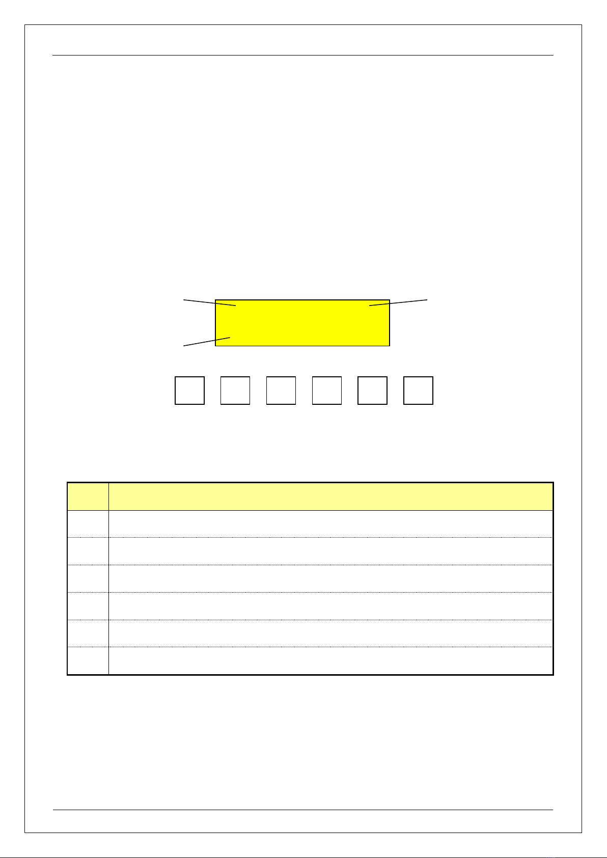
2.1 LCD Keypad Operation Description
LCD Keypad has six keys, the arrangement and definition as below: -
The functions of the keys are: -
Key
Description
Menu
Unconditionally return to main menu.
Enter
To enter to the next level of menu, to confirm the modified value or the car call registration.
Esc
To escape to the upper level of menu or to cancel the amendment.
>
Right scrolling cursor or to viewing communication status and grouping status in main menu.
Λ
To scroll up one screen, to increase parameter value by one or to select YES (ON).
V
To scroll down one screen, to decrease parameter value by one or to select NO (OFF).
Group control board (QKB2) uses the LCD display and keypad operation to set the group control system
operating modes, hall call up and down, car call availabilities, system date and time, On duty and Off duty times,
and to view each elevator running status.
ESC
AB C D E F G H
-1 2 3 4 2 * 19 *
Menu
Λ
V
>
Enter
Running direction
Elevator number
Current floor
number
SJT-WVF-V
Elevator Group Control User Manual
Shenyang Bluelight
Page 4
Ver. 2007
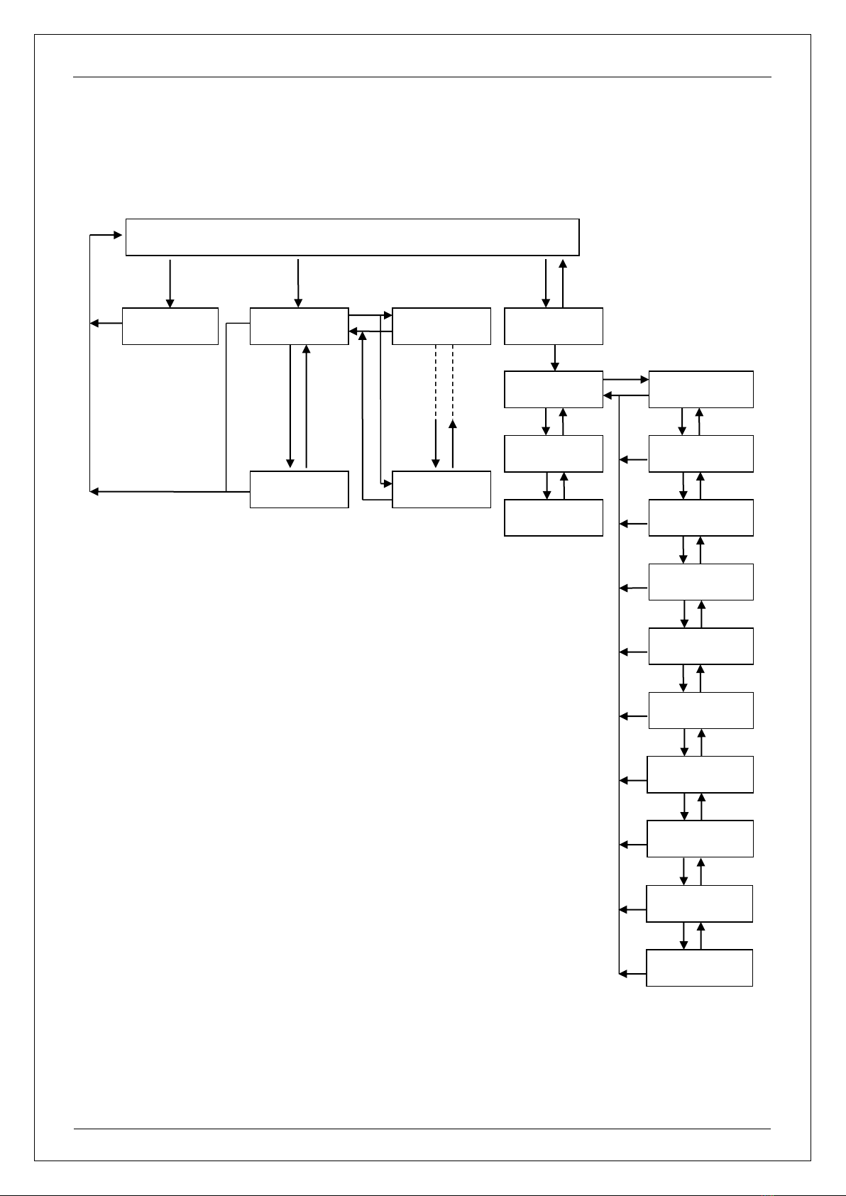
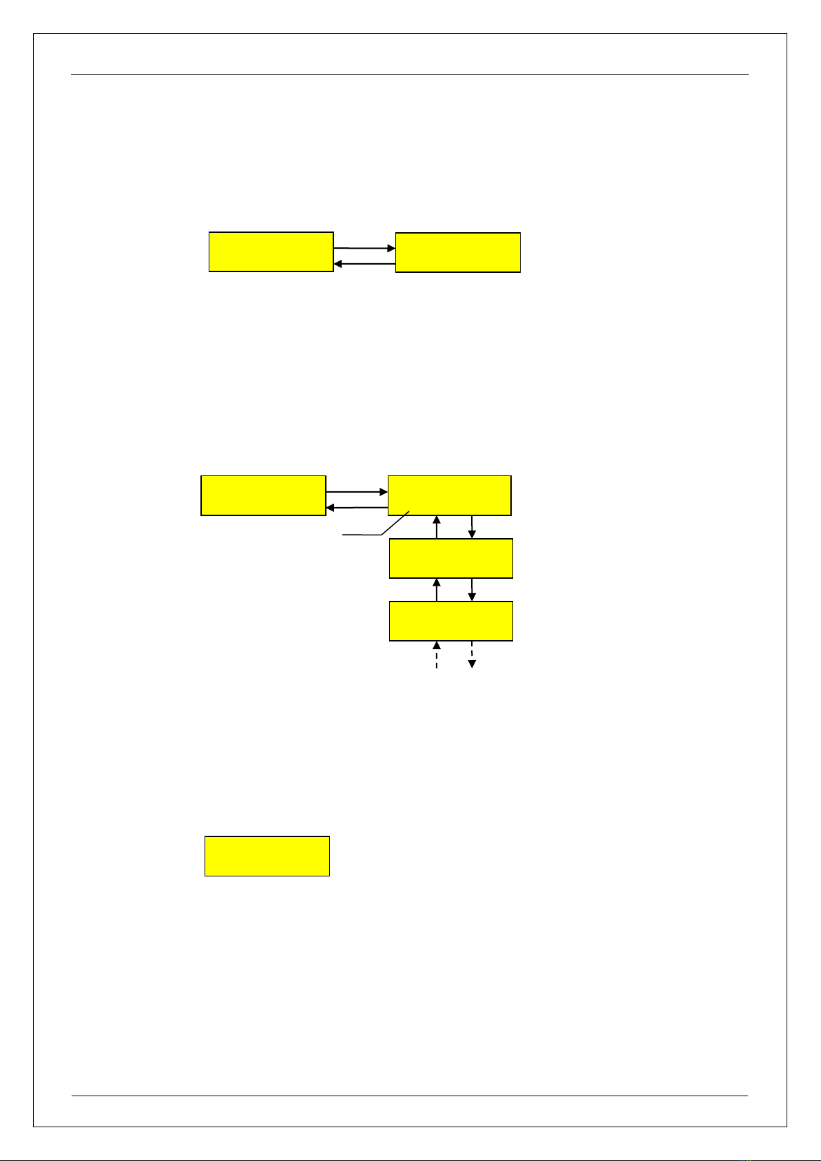
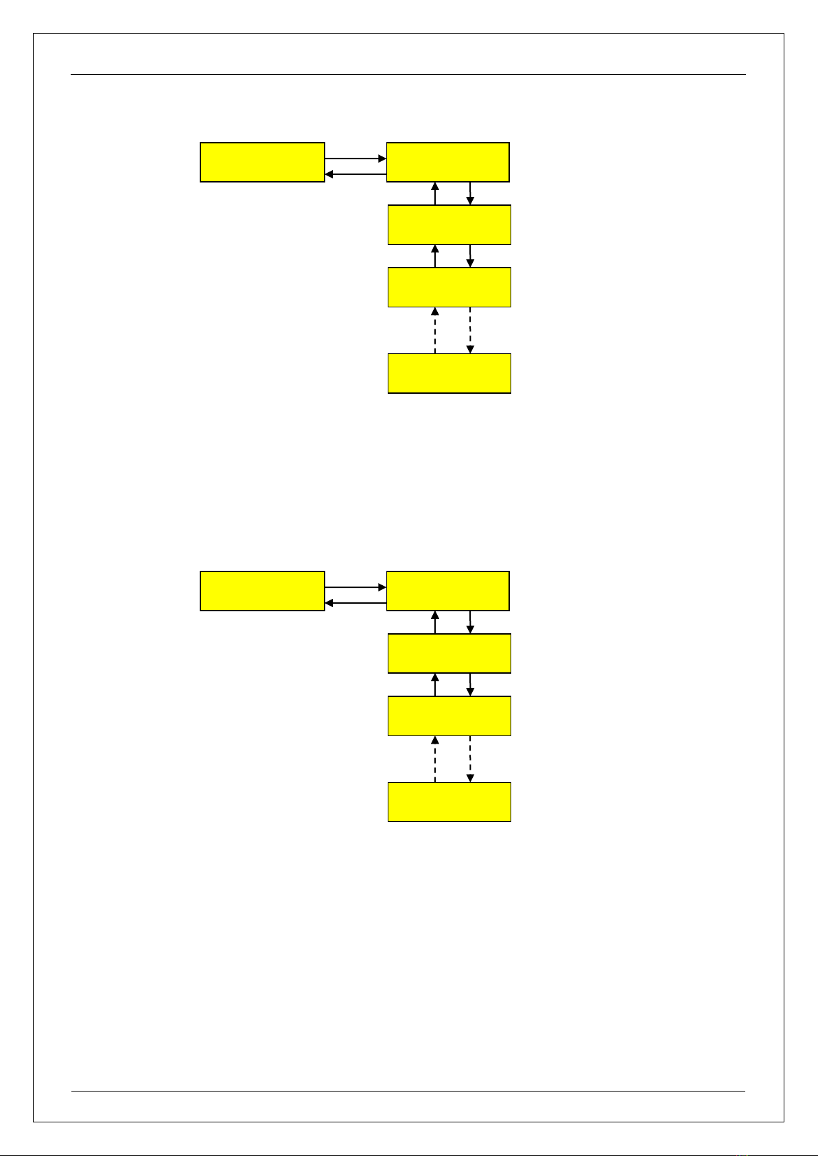
2.2 LCD Display Flowchart and Description
A B C D E F G H
-1 2 4 15 * * * *
Balance mode
Sys: Ok
Elevator state
Enter
Logic state
Enter
Elevator state
A-Enter
Elevator State
H-Enter
Input Password
0000
General Para
Enter
Save Para
Enter
New Password
Enter
Group able set
Enter
S.X.N quotiety
K1:2 K2:2 K3:2
Mode select
Enter
Set time
03-08-18 10:20
S Start Time
08:10
S Stop Time
09:00
X Start Time
16:55
X Stop Time
17:30
Esc
Esc
Esc
Enter
Enter
Esc
Esc
Esc
Esc
Esc
Esc
Esc
Esc
Esc
Esc
>
V
n: Stop Floor
Enter
n: Homing Floor
Enter
Esc
Esc
SJT-WVF-V
Elevator Group Control User Manual
Shenyang Bluelight
Page 5
Ver. 2007
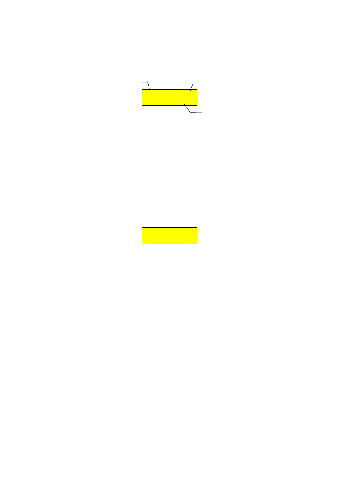
2.3 LCD Display Main Menu Description
A, B, C, D, E, F, G and H are representing the eight elevator numbers; the arrow beside it is indicating the elevator
running direction; the number or alphabet below the elevator number is showing the current actual floor
number; if a symbol “*” is under the elevator number, it means there is communication abnormal or “Group able
set” is set to “NO” (or it may be set to Mode:0 in that elevator main control board Group control function)
2.4 Group Control Status and Communication
Balance mode : Hall calls are being divided into groups so as to serve the hall call registration as soonest as
possible.
On duty mode : Elevators are assigned to homing floor to serve up peak traffic during the preset time.
Off duty mode : One elevator is assigned to serve up traffic, the rest of the elevator in the group are
assigned to serve down traffic.
Sys: ok : Group control communication is normal.
Sys: ET : Group control communication is abnormal.
Balance mode
Sys: ok
AB C D E F G H
-1 2 3 4 G * 19 *
Running direction
Elevator number
Actual floor number
SJT-WVF-V
Elevator Group Control User Manual
Shenyang Bluelight
Page 6
Ver. 2007
2.5 Each Elevator Status and Description
Note: “X” is representing the elevator number from “A” to “H”.
Item
Description
Item
Description
Item
Description
X00
Parking
X08
Over Load
X16
Load Weighting Fault
X01
Total Control
X09
Light Load
X17
FJ-CZB Fault
X02
Inspection
X10
Full Load
X18
X03
Door Interlock Contact
X11
Attendant Y/N
X19
Emergency Stop
X04
Speed Change
X12
Fault
X20
Door Zone
X05
Running
X13
Fireman
X21
Door Fault
X06
Down Direction
X14
VIP
X22
Door Open Fault
X07
Up Direction
X15
Buzzer
X23
Door Close Fault
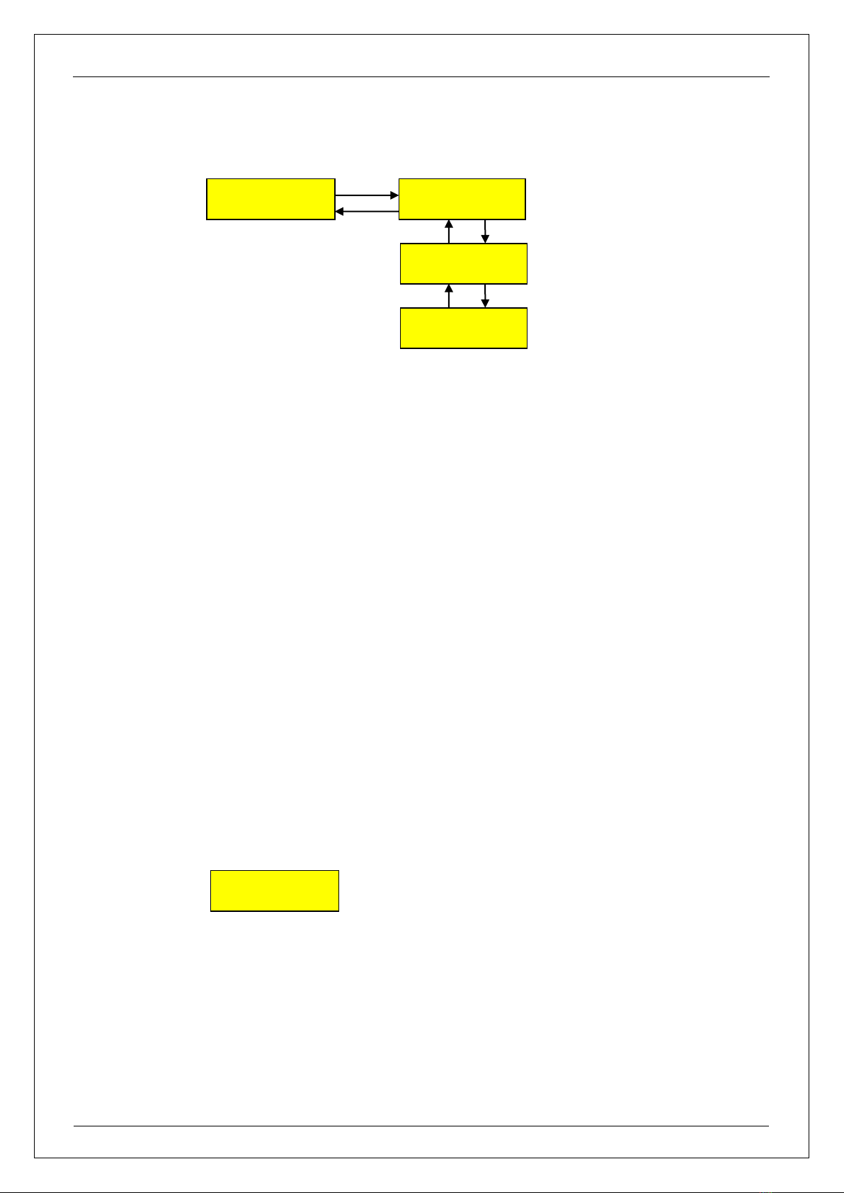
2.6 Group Control Board Internal Logic Status
(For internal used only)
Elevator State
A-Enter
A00A01A02A03
A04A05A06A07
Enter
Esc
A08A09A10A11
A12A13A14A15
A16A17A18A19
A20A21A22A23
Elevator State
Enter
Enter
Esc
Elevator State
H-Enter

SJT-WVF-V
Elevator Group Control User Manual
Shenyang Bluelight
Page 7
Ver. 2007
2.7 Password Setting
Password (User Level or Factory Level) must be correctly entered in order to enter into Parameter Setting menu.
In the Input Password menu, use “Λ” key to increase the number, or “V” key to decrease the number, use “>” key
to scroll the desired password position. Press “Enter” key to enter the correct password, hence to enter into the
General Parameter setting menu. Or else it will display:
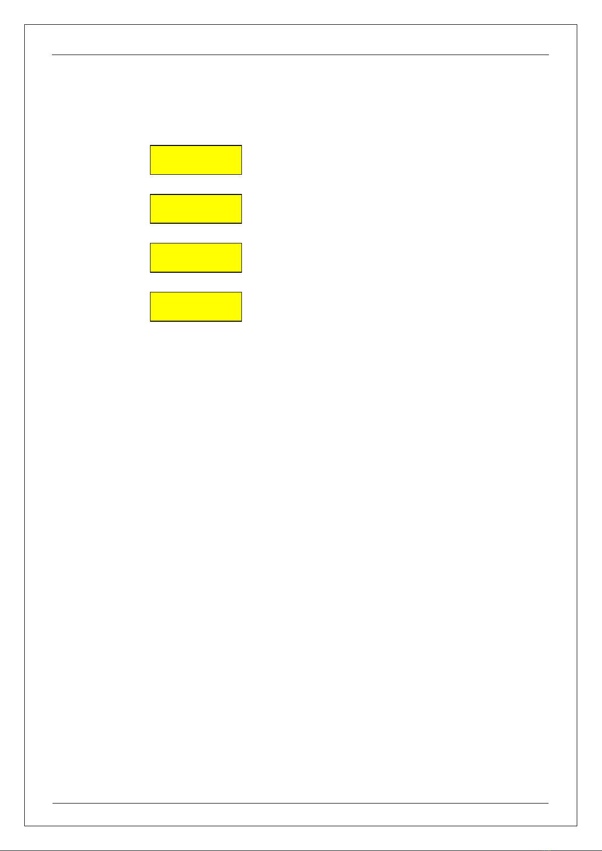
2.8 Save Parameter
After entering into “Save Para” menu, press “Enter” to select “Yes”, the system will automatically save the
amended parameter. “Success” will be displayed if the saving is succeeded, or else “Failure” is shown. If the
saving is failed, please contact factory for further assistance.
Note: Any changes in parameter setting will be effective immediately, however, if “Save Para” is not performed,
when system power is cut off, the changed parameter setting will be reverted to before value.
Save Para
Enter
Save Para
Yes ?
Enter
Esc
Save Para
Waiting………
Save Para
Success
Enter
Save Para
Failure
Esc
Esc
Password Error
Enter
Input Password
0000 Enter
SJT-WVF-V
Elevator Group Control User Manual
Shenyang Bluelight
Page 8
Ver. 2007
2.9 Change Password
It is for changing and setting new User Password.
2.10 General Parameter Settings
2.10.1 Group able set
Set “Yes” for the each elevator in the group bank.
2.10.2 S.X.N quotient
The value K1, K2 and K3 are for internal use, do not change the factory setting. (Note: “S” = Up Hall Call, “X” =
Down Hall Call and “N” = Car Call)
S.X.N quotient
K1: 2 K2: 2 K3: 3
Group able set
Enter
Group able set
A: Yes/No
Enter
Esc
Group able set
B: Yes/No
Elevator number
Group able set
C: Yes/No
New Password
Enter
New Password
0 0 0 0
Enter
Esc
SJT-WVF-V
Elevator Group Control User Manual
Shenyang Bluelight
Page 9
Ver. 2007
2.10.3 Mode Select
Mode 0 : spare, not used.
Mode 1 : On Duty Mode; if “Yes”, during the preset “On Duty” time, the Group system will enter the On Duty
Mode.
Mode 2 : Off Duty Mode; if “Yes”, during the preset “Off Duty” time, the Group system will enter the Off Duty
Mode.
When “On Duty Mode” is set to “Yes”, during the prefix start working hours, the group control system will enter
On Duty mode; when “Off Duty Mode” is set to “Yes”, during the prefix finish working hours, the group control
system will enter Off Duty mode;if “On Duty Mode” is set to “No”, the group control system will never enter On
Duty mode; similarly, if “Off Duty Mode” is set to “No”, the group control system will never enter Off Duty mode.
If both “On Duty Mode” and “Off Duty Mode” are set to “No”, then the group control system will be operated in
averaging running mode.
2.10.4 Set System Time
To display and to set the system date & time; YY-MM-DD HH:MM
Set Time
03-03-16 08:18
Mode Select
Enter
Mode Select
Mode 0: Yes/No
Enter
Esc
Mode Select
Mode 1: Yes/No
Mode Select
Mode 2: Yes/No
SJT-WVF-V
Elevator Group Control User Manual
Shenyang Bluelight
Page 10
Ver. 2007
2.10.5 Set On Duty Time / Off Duty Time
When “On Duty Mode” is set to “Yes”, group control system will enter On Duty mode between the start and stop
On Duty mode times.
When “Off Duty Mode” is set to “Yes”, group control system will enter Off Duty mode between the start and stop
Off Duty mode times.
When “On Duty Mode”and “Off Duty Mode”have been set to “Yes”, if the system time is greater than “S Start
Time” and smaller than “S Stop Time”, the Group system will enter the “On Duty Mode”; If the system time is
greater than “X Start Time” and smaller than “X Stop Time”, the Group system will enter the “Off Duty mode”.
Note: “S” stands for Up Peak On Duty; “X” is stands for Down Peak Off Duty.
S Start Time
08:20
S Stop Time
09:20
X Start Time
16:20
X Sop Time
17:20
Start time for On Duty Mode
Stop time for On Duty Mode
Start time for Off Duty Mode
Stop time for Off Duty Mode
SJT-WVF-V
Elevator Group Control User Manual
Shenyang Bluelight
Page 11
Ver. 2007
2.10.6 Set Non-Stop Floor
If there is any non-stop floors setting required in the Group control system, the non-stop floor setting in every
main control board must be similar to the setting in Group control system.
Please be noted that the Main control board is using actual floor number(s) in the non-stop floor setup, whereas,
the Group control system is using relative floor number(s) in the non-stop floor setup. If the setup of non-stop
floor is wrong (non-stop floor set in Main control board is not corresponding to the non-stop floor set in Group
control system), the system will have conflict in responding to registered calls (like travelling directions and run
contactor (KDY) ON-OFF repeatedly).
When setting up the non-stop floor in Group control system, all elevators (A to H) must be set to the same
configuration. If there is any inconsistent setting on every elevator, (for example, Floor “02” is set to “ON” in
Elevator-A, but Floor “02” is set to “OFF” in Elevator-B), then the Group control will perform call distribution
wrongly for passengers who want to travel to Floor “02”.
General Para
Enter
A: Stop Floor
Enter
Enter
Esc
B: Stop Floor
Enter
C: Stop Floor
Enter
H: Stop Floor
Enter
SJT-WVF-V
Elevator Group Control User Manual
Shenyang Bluelight
Page 12
Ver. 2007
2.10.7 Set Homing Floor
This function is available for software version 706_12 and higher versions.
When the elevator group is idle (no car and hall calls for 5 minutes), if the Homing Floor is set to “0” for every
elevator in the group control system, the group control system will automatically distribute the elevators to
average region based on number of floor; for example, if there is a 20 floors building having 3-car Group control
system, Elevator-A will be distributed to Floor 01 for waiting call, Elevator-B will be distributed to Floor 06 for
waiting call and Elevator-C will be distributed to Floor 12 for waiting call.
General Para
Enter
A: Homing Floor
Enter
Enter
Esc
B: Homing Floor
Enter
C: Homing Floor
Enter
H: Homing Floor
Enter
A: Stop Floor
Enter
A: Stop Floor
01: ON / OFF
Enter
Esc
A: Stop Floor
02: ON / OFF
A: Stop Floor
03: ON / OFF
A: Stop Floor
64: ON / OFF

SJT-WVF-V
Elevator Group Control User Manual
Shenyang Bluelight
Page 13
Ver. 2007
When the setting of Homing Floor is not “0”, the elevator will be distributed to the designated floor when it is
idle for 5 minutes.
Remarks:
(1) If Group control Homing Floor is not utilized (all set to “0”), the Group control system will
distribute the elevators to average region for waiting calls.
(2) During Group controlling, the Homing Floor setup of every Main control board will be null and void
(3) The Group control system is using absolute relative floor number(s) in the Homing Floor setup.
(“1” = lowest floor, so on and so forth)
2.11 Setting requirement for Group Control versus elevator numbers (A, B, C, …)
(1) On every elevator controller of the group control, the setting for fireman “Fire Floor” and “Homing
Floor” must be the same;
(2) In Group control system (3-car group and above), if the bottom floors are not same (some elevators
are having basement floors), the most lowest floor elevator should be set to Elevator A, the second
most should be set to Elevator B and so on and so forth; If the bottom floors are same whereas the
top floors are not same, hence the highest floor elevator should be set to Elevator A; If none of the
above mentioned, elevator numbers can be randomly set.
A: Homing Floor
Enter
A: Homing Floor
00
Enter
Esc
SJT-WVF-V
Elevator Group Control User Manual
Shenyang Bluelight
Page 14
Ver. 2007
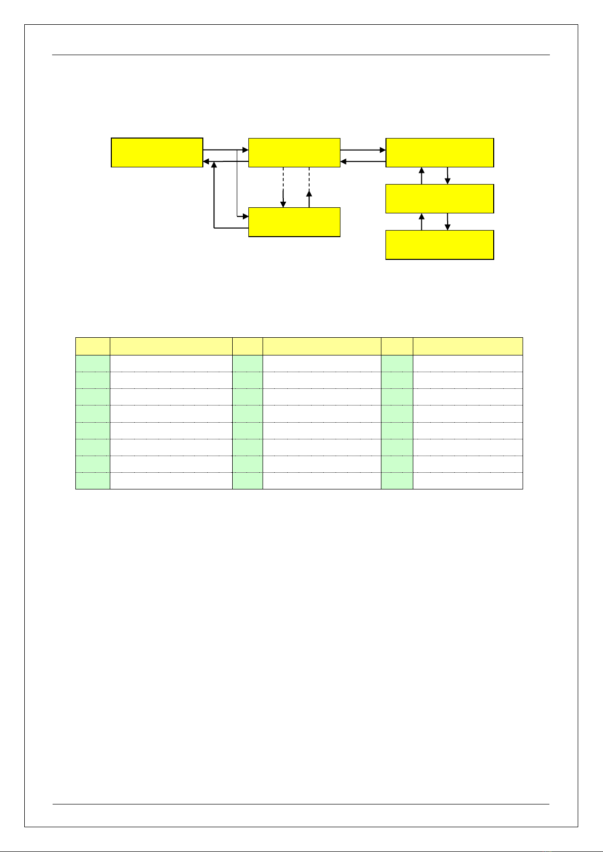
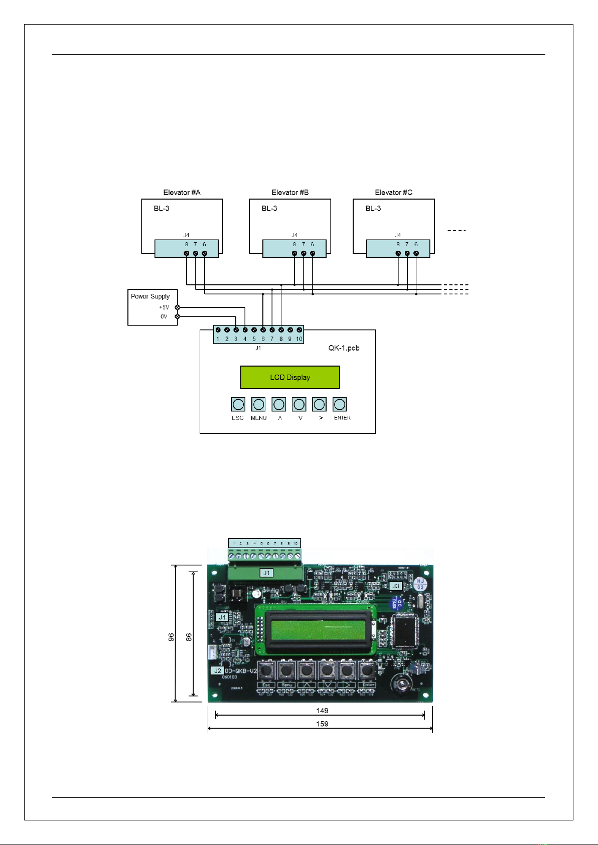
Appendix 1Group Control and Main Control Board System Block Diagram
Appendix 2Group Control Board Dimensions

SJT-WVF-V
Elevator Group Control User Manual
Shenyang Bluelight
Page 15
Ver. 2007
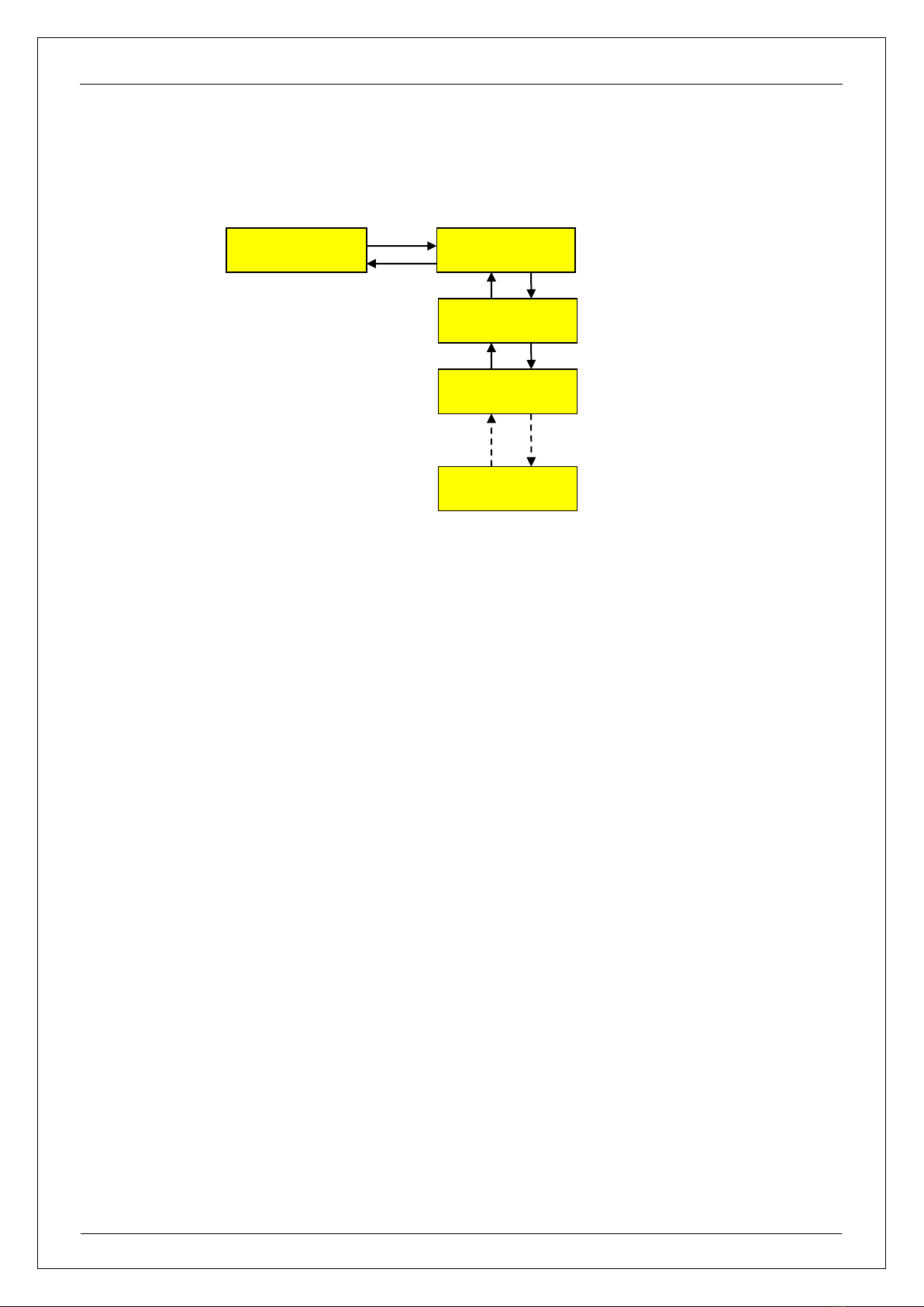
Group Control Manual: Additional Description (2007-4-7)
In case of Group control, the terminal resistor of main control board for group control communication must be
removed except the Group control card QK-1 and the furthest Main control board. See below diagrams:-
Remove the terminal resistors R287 & R252 (which resistor has marking 620, i.e. 62 ohm) near to J4 of Main
control boards from board 1 to board N-1.
Remain the terminal resistors on Group control card and the furthest Main control board N.
Main Control Board
1
Main Control Board
N-1
Main Control Board
N
Group Control Card
QK-1
CAN Comm. Line
Table of contents


