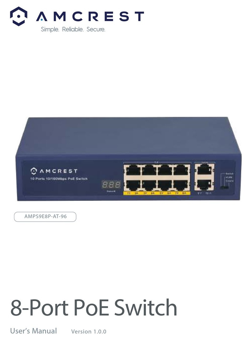
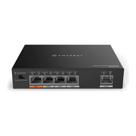
Amcrest AMPS9E8P-AT-96 User manual

4/8-Port PoE Switch
User’s Manual V. 1.0.0
Simple. Reliable. Secure.
4/8-Port PoE Switch
User’s Manual V. 1.0.0
Simple. Reliable. Secure.

Important
Safeguards & Warnings
Attention:
Please read the following safeguards and warnings carefully before using the product in order to avoid damages and
losses.
Note:
Do not expose the device to Soot, high humidity or dust. Doing so may cause fire or electric shock.
Do not install the device in direct sunlight as it may cause overheating and failure.
Installation of the unit should be via the compatible rack mount or securely on a flat surface.
Do not place the device on carpet or other insulating surfaces. Ex. Rugs, towels, rags, clothing, etc.
Do not block or impede airflow to or around the unit. Doing so may cause overheating, failure or fire.
Do not place stack or place objects on the unit.
This unit contains no user serviceable parts. Servicing should only be performed by approved technicians.
Warning:
Do not use a power supply other than the provided manufacturer power supply. Failure to do so may cause unit failure
and/or damage.
Special Announcement:
This manual is for reference only.
All the designs and software here are subject to change without prior written notice.
All trademarks and registered trademarks are the properties of Amcrest Technologies LLC.
Applicable Models:
The manual can be applied to the following models:
MODEL NUMBERS PENDING: AMPS5E4P-AT-58, AMPS9E8P-AT-96

Table
of Contents
1 Product Overview 3
1.1 Features 3
1.2 Typical Application 3
2Device Structure 4
2.1 4-Port PoE Switch 4
2.1.1 Front Panel 4
2.1.2 Upper Cover 4
2.1.3 PoE Power Supply 4
2.2 8-Port PoE Switch 5
2.2.1 Front Panel 5
2.2.2 Upper Cover 5
2.2.3 PoE Power Supply 5
3 Installation Guide 6
4 Appendix 1 Technical Specification 7

Product Overview
1.1 Features
Common Features:
Two-layer industrial POE switch.
Conform to IEEE802.3, IEEE802.3u, IEEE802.3ab/z and IEEE802.3X standards.
MAC auto study and aging, MAC address list capacity is 8K.
All ports self-adapt MDI/MDIX mode.
All the10/100M self-adaptive RJ45 ports support IEEE802.3af, IEEE802.3at standard power supply.
Industrial wide temperature design.
Support DC 53V power supply.
Individual Features:
4-port PoE switch 1 100/1000M self-adaptive SFP fiber port, 1*10/100/1000M self-adaptive RJ45 port and 4 10/100M self-adap-
tive RJ 45 ports.
4-port PoE switch with 60W power adapter.
8-port PoE switch supports 1 1000M SFP fiber port, 1*10/100/1000M self-adaptive RJ45 port and 8 10/100M self-adaptive RJ 45
ports.
8-port PoE switch with 96W power adapter.
1.2 Typical Application
The typical application of the device is shown in Figure 1- 1
3
POE Ethernet
NVRSwitch
Amcrest 4/8
Port Switch
Amcrest 4/8
Port Switch
Amcrest 4/8
Port Switch
Camera
Camera
Camera
POE
Optical
POE
Figure 1.1
Device Structure
2.1 4-Port PoE Switch
2.1.1 Front Panel
The front panel is shown in Figure 2-1.
2.1.2 Upper Cover
The unit power port is shown in Figure 2-2, support DC 48-57V power supply.
2.1.3 PoE Power Output
10/100M RJ45 Ports support both IEEE802.3af, and IEEE802.3at power standards.
Supports simultaneous power to 4 ports using IEEE802.3af
Supports Simultaneous power to 2 ports using IEEE802.3at
2.2 8-Port PoE Switch
2.2.1 Front Panel
The front panel is shown in Figure 2-1.
2.2.2 Upper Cover
The device power port is shown in Figure 2-4, support DC 48-57V power supply.
2.2.3 PoE Power Supply
Elaboration needed: 8 10/100M RJ45 ports support IEEE802.3af, IEEE802.3at standard power supply.
Elaboration needed: Support several RJ45 Ports IEEE802.3af and IEEE802.3at standard power supply simultaneously,
total power consumption of PoE power supply is less than 93W.
Installation Guide
The 4 and 8 port PoE switch support DIN rail mounting. Insert the top
of the DIN rail in the hooked section of the upper mount.
Now firmly press the PoE switch straight back onto the rail until it is
secured firmly. see Figure 3-1.
Appendix 1
Technical Specification

Product Overview
1.1 Features
Common Features:
Two-layer industrial POE switch.
Conform to IEEE802.3, IEEE802.3u, IEEE802.3ab/z and IEEE802.3X standards.
MAC auto study and aging, MAC address list capacity is 8K.
All ports self-adapt MDI/MDIX mode.
All the10/100M self-adaptive RJ45 ports support IEEE802.3af, IEEE802.3at standard power supply.
Industrial wide temperature design.
Support DC 53V power supply.
Individual Features:
4-port PoE switch 1 100/1000M self-adaptive SFP fiber port, 1*10/100/1000M self-adaptive RJ45 port and 4 10/100M self-adap-
tive RJ 45 ports.
4-port PoE switch with 60W power adapter.
8-port PoE switch supports 1 1000M SFP fiber port, 1*10/100/1000M self-adaptive RJ45 port and 8 10/100M self-adaptive RJ 45
ports.
8-port PoE switch with 96W power adapter.
1.2 Typical Application
The typical application of the device is shown in Figure 1- 1
4
Device Structure
2.1 4-Port PoE Switch
2.1.1 Front Panel
The front panel is shown in Figure 2-1.
2.1.2 Upper Cover
The unit power port is shown in Figure 2-2, support DC 48-57V power supply.
2.1.3 PoE Power Output
10/100M RJ45 Ports support both IEEE802.3af, and IEEE802.3at power standards.
Supports simultaneous power to 4 ports using IEEE802.3af
Supports Simultaneous power to 2 ports using IEEE802.3at
SN Name Note
1 10/100 Base-T 4 10/100M self-adaptive PoE power supply ports.
2 10/100/1000 Base-T 10/100/1000M self-adaptive RJ45 port.
3 100/1000 Base-X 100/1000M self-adaptive SFP fiber port.
4 Link/Act Fiber port status indicator
5 PWR Power indicator
Sheet 2-1
DC48-57V
Figure 2.2
1
2
3
4
5
6
PWR
Link/Act
1000 Base-X
10/100/1000 Base-T
10/100 Base-T + POE
1 2 3 4 5
Figure 2.1
2.2 8-Port PoE Switch
2.2.1 Front Panel
The front panel is shown in Figure 2-1.
2.2.2 Upper Cover
The device power port is shown in Figure 2-4, support DC 48-57V power supply.
2.2.3 PoE Power Supply
Elaboration needed: 8 10/100M RJ45 ports support IEEE802.3af, IEEE802.3at standard power supply.
Elaboration needed: Support several RJ45 Ports IEEE802.3af and IEEE802.3at standard power supply simultaneously,
total power consumption of PoE power supply is less than 93W.
Installation Guide
The 4 and 8 port PoE switch support DIN rail mounting. Insert the top
of the DIN rail in the hooked section of the upper mount.
Now firmly press the PoE switch straight back onto the rail until it is
secured firmly. see Figure 3-1.
Appendix 1
Technical Specification

Product Overview
1.1 Features
Common Features:
Two-layer industrial POE switch.
Conform to IEEE802.3, IEEE802.3u, IEEE802.3ab/z and IEEE802.3X standards.
MAC auto study and aging, MAC address list capacity is 8K.
All ports self-adapt MDI/MDIX mode.
All the10/100M self-adaptive RJ45 ports support IEEE802.3af, IEEE802.3at standard power supply.
Industrial wide temperature design.
Support DC 53V power supply.
Individual Features:
4-port PoE switch 1 100/1000M self-adaptive SFP fiber port, 1*10/100/1000M self-adaptive RJ45 port and 4 10/100M self-adap-
tive RJ 45 ports.
4-port PoE switch with 60W power adapter.
8-port PoE switch supports 1 1000M SFP fiber port, 1*10/100/1000M self-adaptive RJ45 port and 8 10/100M self-adaptive RJ 45
ports.
8-port PoE switch with 96W power adapter.
1.2 Typical Application
The typical application of the device is shown in Figure 1- 1
5
Device Structure
2.1 4-Port PoE Switch
2.1.1 Front Panel
The front panel is shown in Figure 2-1.
2.1.2 Upper Cover
The unit power port is shown in Figure 2-2, support DC 48-57V power supply.
2.1.3 PoE Power Output
10/100M RJ45 Ports support both IEEE802.3af, and IEEE802.3at power standards.
Supports simultaneous power to 4 ports using IEEE802.3af
Supports Simultaneous power to 2 ports using IEEE802.3at
SN Name Note
1 10/100 Base-T 8 10/100M self-adaptive RJ45 ports, which are used for PoE power supply.
2 10/100/1000 Base-T 10/100/1000M self-adaptive RJ45 port.
3 100/1000 Base-X 100/1000M self-adaptive SFP fiber port.
4 Link/Act Fiber port status indicator
5 PWR Power indicator
Sheet 2-2
DC48-57V
Figure 2.4
5
6
7
8
1
2
3
4
9
10
PWR
Link/Act
1000 Base-X
10/100/1000 Base-T
10/100 Base-T + POE
1 2 3 4 5
Figure 2.3
2.2 8-Port PoE Switch
2.2.1 Front Panel
The front panel is shown in Figure 2-1.
2.2.2 Upper Cover
The device power port is shown in Figure 2-4, support DC 48-57V power supply.
2.2.3 PoE Power Supply
Elaboration needed: 8 10/100M RJ45 ports support IEEE802.3af, IEEE802.3at standard power supply.
Elaboration needed: Support several RJ45 Ports IEEE802.3af and IEEE802.3at standard power supply simultaneously,
total power consumption of PoE power supply is less than 93W.
Installation Guide
The 4 and 8 port PoE switch support DIN rail mounting. Insert the top
of the DIN rail in the hooked section of the upper mount.
Now firmly press the PoE switch straight back onto the rail until it is
secured firmly. see Figure 3-1.
Appendix 1
Technical Specification

Product Overview
1.1 Features
Common Features:
Two-layer industrial POE switch.
Conform to IEEE802.3, IEEE802.3u, IEEE802.3ab/z and IEEE802.3X standards.
MAC auto study and aging, MAC address list capacity is 8K.
All ports self-adapt MDI/MDIX mode.
All the10/100M self-adaptive RJ45 ports support IEEE802.3af, IEEE802.3at standard power supply.
Industrial wide temperature design.
Support DC 53V power supply.
Individual Features:
4-port PoE switch 1 100/1000M self-adaptive SFP fiber port, 1*10/100/1000M self-adaptive RJ45 port and 4 10/100M self-adap-
tive RJ 45 ports.
4-port PoE switch with 60W power adapter.
8-port PoE switch supports 1 1000M SFP fiber port, 1*10/100/1000M self-adaptive RJ45 port and 8 10/100M self-adaptive RJ 45
ports.
8-port PoE switch with 96W power adapter.
1.2 Typical Application
The typical application of the device is shown in Figure 1- 1
6
Device Structure
2.1 4-Port PoE Switch
2.1.1 Front Panel
The front panel is shown in Figure 2-1.
2.1.2 Upper Cover
The unit power port is shown in Figure 2-2, support DC 48-57V power supply.
2.1.3 PoE Power Output
10/100M RJ45 Ports support both IEEE802.3af, and IEEE802.3at power standards.
Supports simultaneous power to 4 ports using IEEE802.3af
Supports Simultaneous power to 2 ports using IEEE802.3at
Note:
4-port PoE switch supports the
slide width of 28mm.
8-port PoE switch supports the
slide width of 38mm. A
Hook
Side
Buckle
Figure 3.1
AMPS5E4P-AT-58 AMPS9E8P-AT-96
2.2 8-Port PoE Switch
2.2.1 Front Panel
The front panel is shown in Figure 2-1.
2.2.2 Upper Cover
The device power port is shown in Figure 2-4, support DC 48-57V power supply.
2.2.3 PoE Power Supply
Elaboration needed: 8 10/100M RJ45 ports support IEEE802.3af, IEEE802.3at standard power supply.
Elaboration needed: Support several RJ45 Ports IEEE802.3af and IEEE802.3at standard power supply simultaneously,
total power consumption of PoE power supply is less than 93W.
Installation Guide
The 4 and 8 port PoE switch support DIN rail mounting. Insert the top
of the DIN rail in the hooked section of the upper mount.
Now firmly press the PoE switch straight back onto the rail until it is
secured firmly. see Figure 3-1.
Appendix 1
Technical Specification

Product Overview
1.1 Features
Common Features:
Two-layer industrial POE switch.
Conform to IEEE802.3, IEEE802.3u, IEEE802.3ab/z and IEEE802.3X standards.
MAC auto study and aging, MAC address list capacity is 8K.
All ports self-adapt MDI/MDIX mode.
All the10/100M self-adaptive RJ45 ports support IEEE802.3af, IEEE802.3at standard power supply.
Industrial wide temperature design.
Support DC 53V power supply.
Individual Features:
4-port PoE switch 1 100/1000M self-adaptive SFP fiber port, 1*10/100/1000M self-adaptive RJ45 port and 4 10/100M self-adap-
tive RJ 45 ports.
4-port PoE switch with 60W power adapter.
8-port PoE switch supports 1 1000M SFP fiber port, 1*10/100/1000M self-adaptive RJ45 port and 8 10/100M self-adaptive RJ 45
ports.
8-port PoE switch with 96W power adapter.
1.2 Typical Application
The typical application of the device is shown in Figure 1- 1
7
Device Structure
2.1 4-Port PoE Switch
2.1.1 Front Panel
The front panel is shown in Figure 2-1.
2.1.2 Upper Cover
The unit power port is shown in Figure 2-2, support DC 48-57V power supply.
2.1.3 PoE Power Output
10/100M RJ45 Ports support both IEEE802.3af, and IEEE802.3at power standards.
Supports simultaneous power to 4 ports using IEEE802.3af
Supports Simultaneous power to 2 ports using IEEE802.3at
TECHNICAL PARAMETERS AMPS5E4P-AT-58 AMPS9E8P-AT-96
Physical Port
1*100/1000 Base-X 1*1000 Base-X
Network Ports 1*10/100/1000 Base-T 1*10/100/1000 Base-T
4*10/100 Base-T(POE power supply)8*10/100 Base-T(POE power supply)
Technical Index
Exchange Capacity 6.80Gbps 7.60Gbps
Packet Forwarding Rate 3.57Mpps 4.17Mpps
Exchange Mode Store & forward Store & forward
MAC Study MAC auto study, address list capacity 8 KMAC auto study, address list capacity 8K
Common Parameters
Lightning Protection Level Lightning protection level 4 Lightning protection level 4
Indicator Power indic vator, fiber port status indicator Power indicator, fiber port status indicator
Power DC53V power adapter DC53V power adapter
Power Consumption ≤60W ≤96W
Application Humidity 10%〜90% 10%〜90%
High &Low Temperature -30⁰C〜65⁰C -30⁰C〜65⁰C
Weight 480g 540g
Dimension 150mm×100mm×30mm 150mm×100mm×42mm
2.2 8-Port PoE Switch
2.2.1 Front Panel
The front panel is shown in Figure 2-1.
2.2.2 Upper Cover
The device power port is shown in Figure 2-4, support DC 48-57V power supply.
2.2.3 PoE Power Supply
Elaboration needed: 8 10/100M RJ45 ports support IEEE802.3af, IEEE802.3at standard power supply.
Elaboration needed: Support several RJ45 Ports IEEE802.3af and IEEE802.3at standard power supply simultaneously,
total power consumption of PoE power supply is less than 93W.
Installation Guide
The 4 and 8 port PoE switch support DIN rail mounting. Insert the top
of the DIN rail in the hooked section of the upper mount.
Now firmly press the PoE switch straight back onto the rail until it is
secured firmly. see Figure 3-1.
Appendix 1
Technical Specification

2017 © Amcrest Technologies . All rights reserved.
16727 Park Row Houston,
TX 77084-5020
Phone: +1 888 212 7538
Learn more at
www.amcrest.com
Other manuals for AMPS9E8P-AT-96
1
This manual suits for next models
1
Table of contents
Other Amcrest Switch manuals