4211-41 08-24-12 Page 9
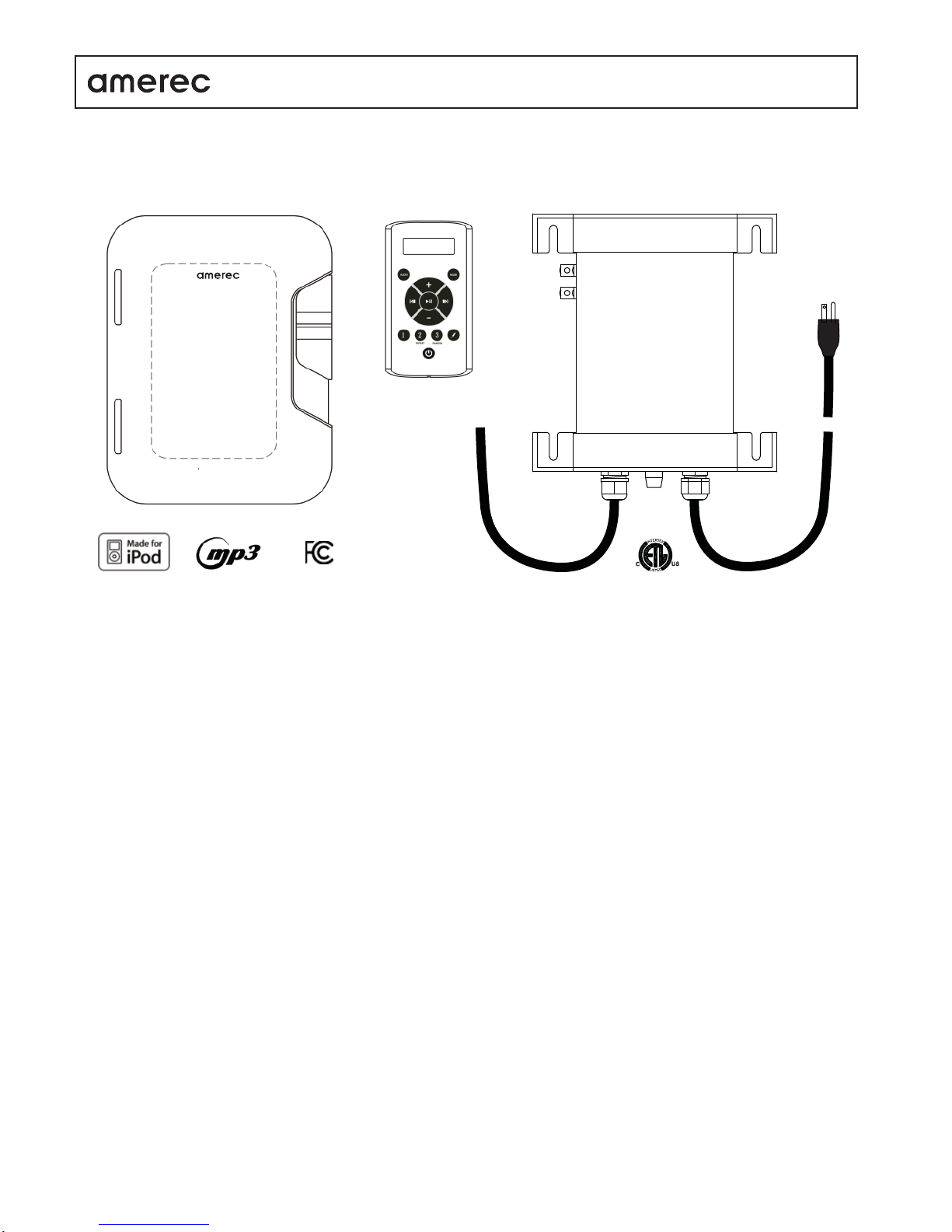
iPOD DOCK, INSTALLATIONAND OPERATING INSTRUCTIONS
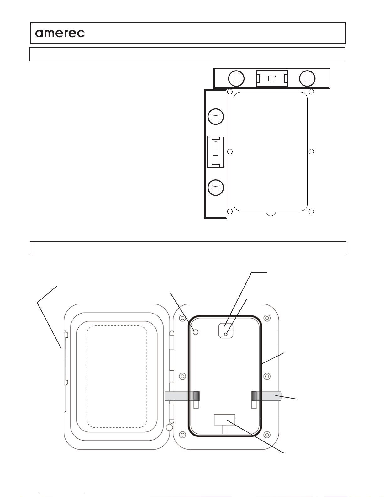
!Be sure the dock is sealed against the wall surface! !Keep the inside of the dock clean and dry!
!Moisture can severely damage the wall or electrical connections!
If the following steps do not correct your problem, contact Technical Support at 1-800-363-0251 for assistance.
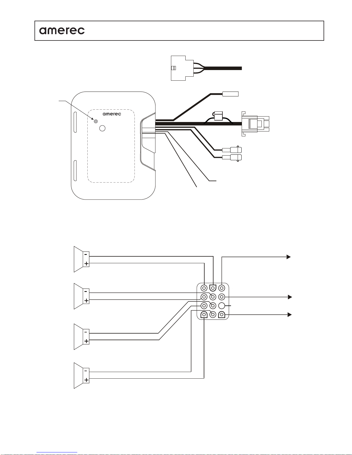
Set-up Make sure the power supply is connected to a 120VAC outlet and properly connected to the Dock. Press the Dock’s ON/OFF
switch and verify its light turns on. If the light does not turn on, check the power supply’s 4Afuse (type T4-AL250VSB) and the Dock’s
15Afuse (see drawing, page 3).
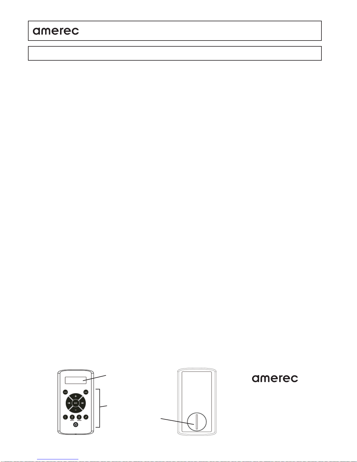
Remote Press a key on the remote. The LCD should display “Welcome” then the selected audio device.
If the Remote displays only two dashes or “No Link”, it is not communicating with the Dock. Make sure the Dock’s power light is on then:
• Move the Remote closer to the Dock. The Remote should normally work within 25 feet of the dock.This range can be affected by wall
materials and other local conditions.
• Has the Remote worked before? If the Remote displays two dashes or “No Link” periodically but does control the Dock properly, you
may need a new battery. See Checking/Replacing the Battery.
• You may need to pair the Remote to its Dock, particularly if this is a new Remote. To pair a Remote to a Dock:
1) Turn the Dock off using its power switch
2) then press a key to turn on the Remote.
3) then press and hold the MODE key until “PAIR” is displayed.
4) while continuing to press the MODE key, turn on the Dock using its power switch and
5) continue pressing the MODE key until “Welcome” is displayed on the Remote.
The Remote and Dock should now be paired.
Checking/Replacing the Battery: If the Remote’s display remains blank when a key is pressed, check or replace the battery.
To check the battery, use a voltmeter to check its voltage. It should be measure 3VDC or higher.
To replace the battery, unscrew the waterproof cap on the back of the Remote control and replace the CR-2430 battery. Replace the
water/dust proof cap.
If the Remote displays correctly but there is no sound, make sure the correct audio device is selected. If the device is correct, then
select a different device to determine if the problem is with the device or the sound system.
• If a different device does not provide sound, change the volume and Front-Rear and Left-Right balances.
• If a different device works correctly, check the iPod connector for moisture or moisture damage. Make sure the device is turned on
and playing audio.
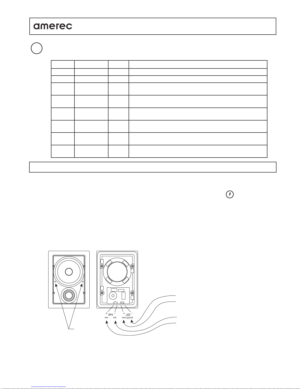
- If the device is an iPod, make sure it is securely connected to the iPod jack.
- If the device is connected to theAUX jack, make sure the cable is securely plugged in at both ends. Turn up the volume on the
audio device (MP3 and similar devices may have low output levels and require higher volume settings when connected used with
the Dock).
- If the FM radio can not find a station when auto-scanning, make sure the antenna is connected. Manually tune in a know FM
station with a good signal then spread the antenna wires out and move them higher or lower or turn them another direction while
listening for a response.
- Remove the device from the Dock and verify it is operating properly on its own.
TROUBLESHOOTING
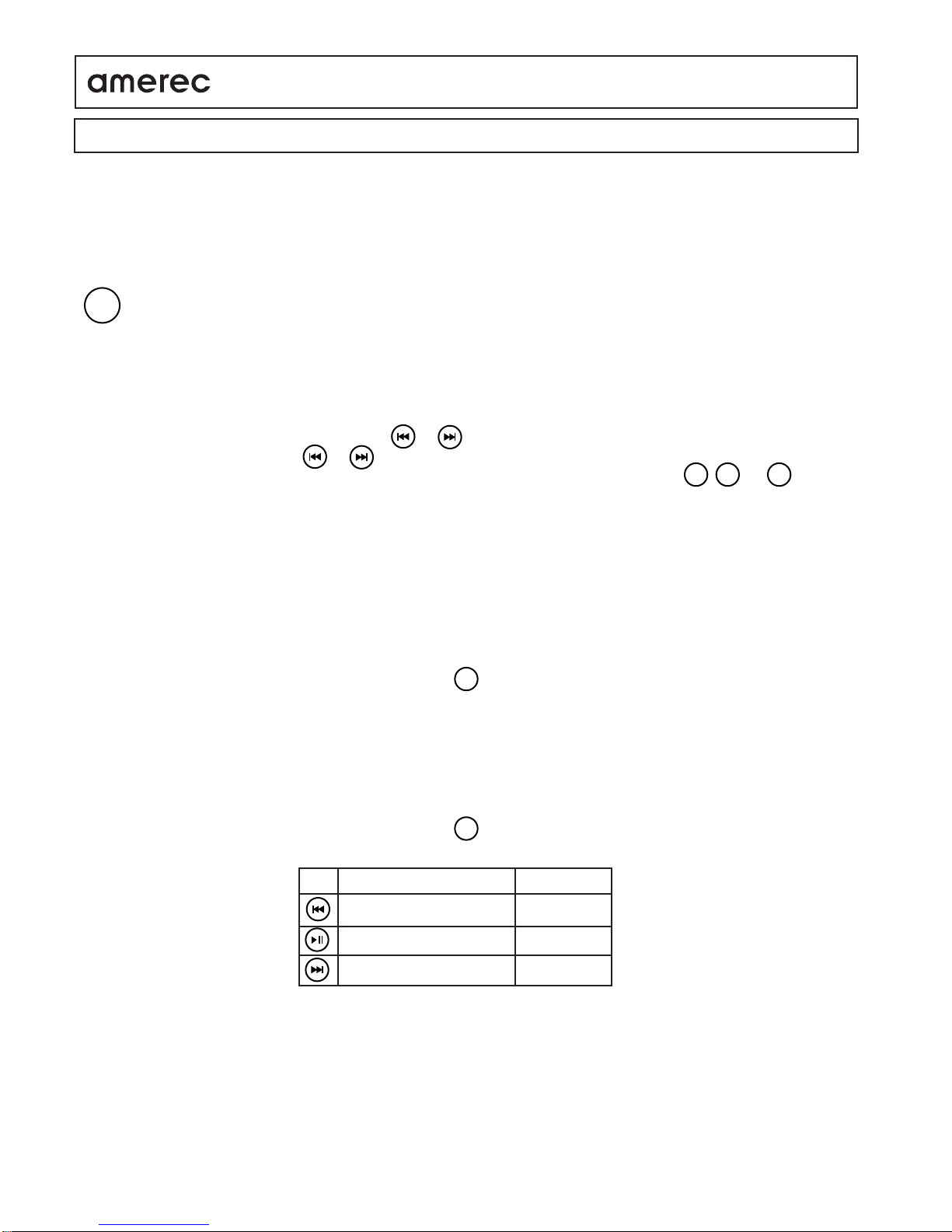
LCD
Function Keys
Battery Door
Technical Support
17683 128th Place NE, Bldg C
Woodinville, WA98072
USA
phone 1-800-363-0251
fax 425-951-1130