Ameresco Solar SK Series User manual

SOLAR ELECTRIC
POWER SYSTEM
INSTALLATION AND
OPERATION MANUAL
SK Series
12V Models

Table of Contents
1. INTRODUCTION ...................................................................................................... 3
1.1 Important: Special Considerations, Before Beginning the Installation................ 3
1.2 Definition of Warning Statements........................................................................ 3
1.3 Technical Support ................................................................................................ 3
2. THEORY OF OPERATION....................................................................................... 4
2.1 System Overview ................................................................................................. 4
2.2 Component Descriptions...................................................................................... 4
3. SYSTEM INSTALLATION....................................................................................... 4
3.1 Overview.............................................................................................................. 4
3.2 Recommended Installation Tools......................................................................... 5
3.3 Site Location ........................................................................................................ 5
3.4 Mechanical Assembly.......................................................................................... 5
3.4.1 Mounting Pole Installation............................................................................ 5
3.4.2 Solar Module Support Structure Assembly .................................................. 5
3.4.3 System Enclosure Mounting......................................................................... 6
3.5 System Wiring...................................................................................................... 6
3.5.1 Grounding..................................................................................................... 6
3.5.2 Array Wiring................................................................................................. 6
3.5.3 Load Wiring.................................................................................................. 6
3.5.4 Battery Installation and Wiring..................................................................... 7
3.6 System Checkout and Commissioning................................................................. 7
4. RECOMMENDED MAINTENANCE....................................................................... 9
4.1 Solar Array........................................................................................................... 9
4.2 Batteries................................................................................................................ 9
4.3 System Wiring...................................................................................................... 9
5. SYSTEM TROUBLESHOOTING............................................................................. 9
APPENDIX....................................................................................................................... 10

D/C SK-12V Page 3Copyright © 2018
August 2018 Ameresco Solar, Inc.
1. INTRODUCTION
Thank you for purchasing an Ameresco Solar, Inc. solar electric power system.
Ameresco Solar is a world leader in design and marketing of solar electric power
systems, with over three decades of experience and sales offices throughout the United
States.
1.1 Important: Special Considerations, Before Beginning the
Installation
To ensure proper operation of the power system, it must be installed per the instructions
in Section 3.
The solar electric system is designed to provide operating power to a specified load.
Using loads other than those for which the system was designed for will result in poor
system performance and possible damage to the batteries.
Special care must be taken when selecting the solar module mounting location to
prevent possible shadowing effects from cut hillsides, trees or utility poles. Any shading
of the modules, during any period of the day, will result in a reduction in the output of
the solar array and reduced system performance and must be avoided.
Additionally, the solar modules must be properly oriented for the specific geographic
region to maximize the solar radiation available at the site. This includes the tilt angle
and alignment to True South.
While performing the installation of your Ameresco Solar system, consideration of the
above factors will result in the system performing reliably to its’ original specifications.
1.2 Definition of Warning Statements
DANGER: Failure to heed this warning may result in serious injury.
CAUTION: Failure to heed this warning may result in damage to the load or system
equipment.
NOTE: Information or instructions that will assist in the proper installation and operation
of the system.
1.3 Technical Support
We strive to provide quality service and support. Please feel free to contact us at any
time should a question arise as to the proper installation and operation of the system. A
proper installation will help to ensure reliable system operation.
Ameresco Solar
120 E. Corporate Place, Suite 8
Chandler, AZ 85225
PH = (480) 760-2500
FX = (855) 255-5364
info@amerescosolar.com

D/C SK-12V Page 4Copyright © 2018
August 2018 Ameresco Solar, Inc.
2. THEORY OF OPERATION
2.1 System Overview
There are three major components in this photovoltaic system: the solar module,
batteries, and the system charge controller. Throughout the year, all the power required
by the load is provided by the solar array.
The PV array will supply current to charge the battery bank. The controller will monitor
the battery voltage and limit the charging current to the battery as required. The
controller will bulk charge the battery to approximately 14.1 VDC, then taper the current
to maintain a float voltage around 13.7 VDC. The controller also contains a temperature
probe and adjusts the charge voltage at a rate of -0.030 VDC/°C from 25°C. (Refer to
the controller manual provided in the kit or document package for additional details on
charge regulation.)
The controller features a Low Voltage Disconnect (LVD) function. This will disconnect
the load if battery voltage falls to approximately 11.5 VDC, during abnormal situations
such as continuous days of cloudy weather. This will prevent the battery from being
over-discharged to a level that could shorten its life. When the battery has been charged
to a voltage of 12.5-12.8 VDC, the controller will reconnect the battery to the load.
2.2 Component Descriptions
Solar Modules
12V nominal 36 cell photovoltaic modules are used in the solar power system. The
modules have an open circuit voltage ranging from 20-24 VDC depending on
temperature and sunlight exposure.Typical peak power voltages are around 17-
18VDC.
Batteries
Deka Solar gel type batteries are used in this system. The Valve Regulated Lead
Acid (VRLA) battery is specifically designed for deep cycle photovoltaic systems.
Refer to the System Wiring Diagram in the appendix for battery capacity details.
Controller
A MorningStar charge controller is used in this system. The controller uses PWM control
of battery charging and features temperature compensation with an internal temperature
probe. Refer to the separate Morningstar manual for additional information on the
controller’s ratings and operation.
3. SYSTEM INSTALLATION
Perform the installation of the system in the order of and as described in the following
subsections.
3.1 Overview
The SK System enclosure is pre-assembled and tested before shipping. All that is
required is to mount the modules and enclosure on a pole (provided by others), install
the batteries, and make the final wire terminations.

D/C SK-12V Page 5Copyright © 2018
August 2018 Ameresco Solar, Inc.
3.2 Recommended Installation Tools
Compass (magnetic or GPS)
Digital Multimeter (DMM)
Phillips & Flat Head Screwdrivers
Wire Cutters & Strippers
Socket Set
Combination Wrench Set
Electrical Tape
Cable Ties (for wire dressing)
3.3 Site Location
1. Shading of the photovoltaic modules will significantly reduce their energy output
and consequently proper battery charging! Be sure to select an array mounting
location that will not be shaded by towers, poles, buildings, vegetation (e.g.
trees), or hillside cuts through the day.
2. In order for the solar array to receive the maximum energy from the sun, the
array must face True South. It is recommended to use a GPS compass to find
True South. Use of a magnetic compass will require adjustment to account for
magnetic declination for your location, which may be over 15 degrees off from
True South in eastern or western USA.
3.4 Mechanical Assembly
WARNING: Electrical Shocks and Burns Hazard
Photovoltaic (PV) modules generate electricity when exposed to light, even when they
are not connected in a circuit. Shocks and burns can result from contact with module
output wiring. These hazards are increased when multiple modules are interconnected
to increase array output current or voltage. Cover module front surfaces completely
with an opaque cloth or other opaque material before performing any operation
involving module or system electrical connections. Use appropriate safety equipment
(insulated tools, insulating gloves, etc.) and procedures.
CAUTION: Module Breakage
The module glass is tempered and will shatter if exposed to impact. Avoid rough
handling and lay the modules on a flat, protected surface during assembly. This will also
prevent power output at the electrical terminals. Avoid shorting the terminals whenever
sunlight is present on the module front surface.
3.4.1 Mounting Pole Installation
All solar equipment is to be attached to a SCH 40 steel pole (provided by others). If
concrete is used, ensure it has had adequate time to cure before placing equipment on
the pole. Refer to the Site Layout drawing in the Appendix for details.
3.4.2 Solar Module Support Structure Assembly
Observe the following mounting and assembly guidelines:
•Refer to the structure assembly instructions included with the structure or
the drawings in the Appendix.
•Generally the array tilt angle should be set to the site latitude plus 15° for
optimum standalone performance. This is typically 55° for most of the
United States.
•Align the structure to True South and adjust to the correct tilt angle.

D/C SK-12V Page 6Copyright © 2018
August 2018 Ameresco Solar, Inc.
3.4.3 System Enclosure Mounting
Using the (2) pole clamps provided, attach the system
enclosure below the solar module. The pole clamps
slide into the slots in the enclosure mounting brackets.
Refer to the Site Layout drawing in the Appendix.
3.5 System Wiring
WARNING: Electrical Hazard
Photovoltaic modules generate high voltage whenever exposed to sunlight. Voltages
may be as high as 24 VDC depending on models used.
CAUTION: Electrical Hazard
Ensure all fuses are removed and all circuit breakers are in the OFF position before
beginning any wiring.
NOTE: Wire Color Code
All pre-installed internal wiring uses the following color code unless specified otherwise
in this manual. RED (+ positive), BLACK (– negative), GREEN or BARE (ground)
3.5.1 Grounding
The system enclosure should be grounded through the ground lug provided on the
bottom of the enclosure. Site grounding wire and hardware are to be provided by
others.
3.5.2 Array Wiring
Route the pre-wired Array cable(s) from the enclosure up the pole to the solar
module(s). Depending on module type; two conductor jacketed Tray Cable may be
used, or a pair of single conductor PV wires with MC4 style male/female connectors. If a
module interconnect wire is included, install it between the modules first and connect as
shown in the System Wiring Diagram.
For Tray Cable connections; route the cable into the module’s junction box and
secure the cord grip, terminate the wires at the module’s terminal block.
For PV wire MC4 wiring; at the module, connect the male and female MC4 connectors
to the enclosure’s cables, ensure the connectors seat fully. Refer to the System Wiring
Diagram in the Appendix.
3.5.3 Load Wiring
If not pre-installed in the system enclosure, route cable or conduit (provided by others)
from the system enclosure to the load and secure/seal with an appropriate connector.
The LOAD terminal blocks accept up to #10 AWG wire. Terminate the wires to the
LOAD terminals and confirm proper polarity. Terminate wiring at the loads as
appropriate. Refer to the System Wiring Diagram in the Appendix.

D/C SK-12V Page 7Copyright © 2018
August 2018 Ameresco Solar, Inc.
3.5.4 Battery Installation and Wiring
WARNING: Electrical Hazard
Batteries contain high discharge currents, use insulated tools on and around batteries.
Keep all battery wiring isolated from other wires or conductive materials until all wires
are connected.
WARNING: Chemical Hazard
Batteries contain sulfuric acid which can cause burns and other serious injury. In the
event of contact with sulfuric acid, flush immediately and thoroughly with water. The
use of safety goggles, rubber apron, and rubber gloves is recommended.
WARNING: Explosive Hazard
Batteries can generate explosive gases, which when released, can explode and cause
blindness and other serious injury. Keep sparks, flames, and smoking materials away
from the battery area.
Place the battery in the enclosure and connect the battery cables to the battery; Red to
positive and Black to negative. If additional batteries are used, install in the same
manner. Refer to the System Wiring Diagram & Enclosure Layout in the Appendix.
3.6 System Checkout and Commissioning
At the end of the installation it is important to confirm and verify all mechanical and
electrical connections. Perform the following system checkout and complete the
System Installation Checklist.
1. Confirm the proper tilt angle and orientation of the solar array; ensure it is facing
true south (and adjusted for magnetic declination if a magnetic compass is used).
2. Ensure all mechanical fasteners are tight and secure.
3. At the controller assembly, check the voltage and polarity of the battery. The
voltage should be approximately 12.5 VDC.
4. At the controller assembly, record the open circuit voltage (Voc) and short circuit
current (Isc) of the array input. Confirm proper polarity.
5. Switch ON the BATTERY circuit breaker (or install fuse). Switch on the ARRAY
circuit breaker if present.Verify the green "CHARGING" indicator on the controller
is lit. If it is not lit, go back and check the connections.
6. Switch on the LOAD circuit breaker (if present), switch on the load(s) and verify its’
proper operation. Ensure the load is operating within the energy design of the
system. If needed perform a series current draw.

D/C SK-12V Page 8Copyright © 2018
August 2018 Ameresco Solar, Inc.
SYSTEM INSTALLATION CHECKLIST AND START-UP DATA TABLE
1. Array facing true south _________ (Yes/No)
Array at correct tilt angle ________ (Yes/No)
2. All mechanical fasteners tight _________ (Yes/No)
3. Record the initial battery voltage at the controller.
Battery ________ VDC
4. Record the array open circuit voltage and short circuit current at the controller.
Open Circuit Voltage ______ VDC
Short Circuit Current ______ A
5. Controller Operation:
Charging LED illuminated _________ (Yes/No)
Load Disconnect LED illuminated _________ (Yes/No)
6. Load operating properly _________ (Yes/No)
INSTALLATION IS NOW COMPLETE
Tested By: __________________________________ Date: _____________
Approved By: ________________________________ Date: _____________

D/C SK-12V Page 9Copyright © 2018
August 2018 Ameresco Solar, Inc.
4. RECOMMENDED MAINTENANCE
Although the solar electric power system should require minimal maintenance a few
minutes time every 3-6 months can help to maintain the performance of the system and
extend its service life.
4.1 Solar Array
The solar array should not need to be completely cleaned unless the dirt build-up
is particularly bad. Special care should be taken to look for and remove any bird
drops or mud as these essentially shade the module and reduce the output
current. When cleaning the front surface of the array use a soft non-abrasive
cloth or brush and water. Avoid the use of any cleaning products that may leave
residue on the module or promote corrosion on the structure and its’ fasteners.
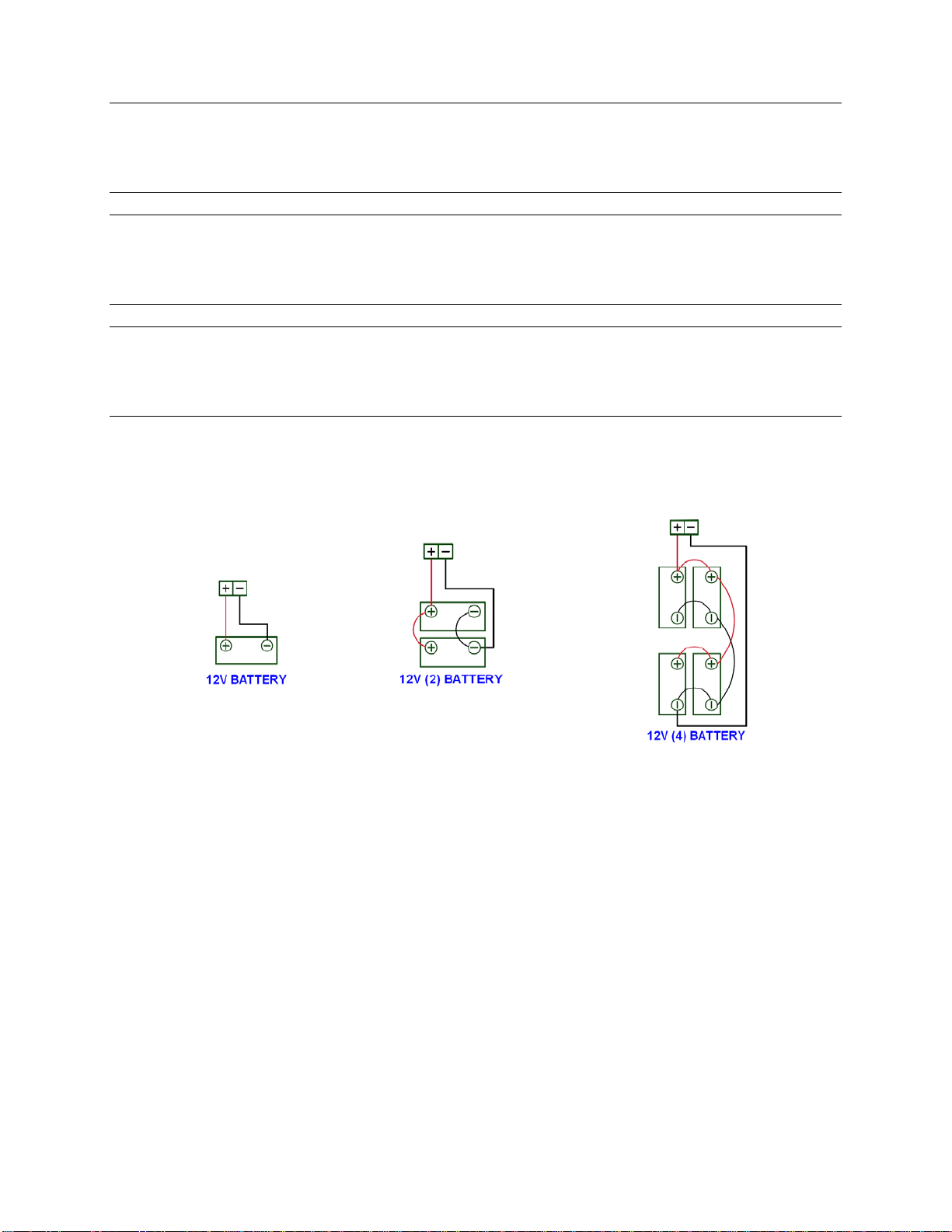
4.2 Batteries
Inspect the battery for corrosion at the terminals and wire connections, clean or
replace terminals if they are damaged. Measure and record battery voltage.
4.3 System Wiring
Inspect all internal and external wiring for damage or corrosion at the system
enclosure, repair or replace as necessary. Re-tighten all accessible wiring
connections.
5. SYSTEM TROUBLESHOOTING
If the system is not functioning correctly, there are a few simple steps to isolate the
problem. The following are some of the typical factors that contribute to the failure of
the system to operate within design parameters:
1. Load greater than system design – Installing loads greater than the system was
designed for will reduce the performance of the system and damage the
batteries. Excessive load operation can either be power, current, or operating
time. Daily load energy consumption should be checked to verify it is within the
operation parameters of the system. If the load is greater than the system
design, the load should be decreased or the system size increased (e.g. array,
battery, controller, etc.)
2. Shading – Even partial shading of the solar module can result in zero output from
the module and will result in reduced system performance. Incorrect orientation
or tilt angle – Refer to the installation instructions in Section 3 for proper
orientation, alignment, and tilt adjustment. Incorrect alignment of the solar array
will result in reduced array output and system performance.
3. Battery failure may be caused by several factors: age, controller failure, or
excessive load operation. If the battery is more than 5 years old is probably
nearing the end of its’ service life and may need to be replaced. A capacity test
can confirm the ability of the battery to support the load. If the battery is relatively
new (1 to 2 years old) the system should be checked for proper operation by
performing the System Checkout in section 3.6.

D/C SK-12V Page 10 Copyright © 2018
August 2018 Ameresco Solar, Inc.
APPENDIX


Table of contents