Ameri-Shred Series 1 User manual

Service Department: 888.270.6879
AMS-150HD/ AMS-150HD-SSD/ AMS-150-SSD
AMS-300HD/ AMS-300HD-SSD/ AMS-300-SSD
OWNER’S MANUAL
SERIES 1 HARD DRIVE
NOTICE: The informaon contained within this manual is correct at me of prinng, but due to the connuing development of prod ucts,
changes in specicaons are inevitable. Ameri-Shred reserves the right to implement such changes without prior noce.

2
Service Department: 888.270.6879
UNLOADING/UNPACKING .........................................................................................................................3
ELECTRICAL INSTALLATION ........................................................................................................................ 4
NAMEPLATE (LOG SHREDDER SPECIFICS) ...................................................................................................4
SAFETY WARNINGS .................................................................................................................................... 5
SHREDDER OPERATION ..............................................................................................................................6
START UP PROCEDURE ...............................................................................................................................7
SERVER DRIVE JAM WARNING ...................................................................................................................8
CLEARING A JAM ........................................................................................................................................9
SHUT DOWN PROCEDURE ......................................................................................................................... 9
CURRENT RELAY ADJUSTMENT................................................................................................................... 9
TROUBLESHOOTING ...................................................................................................................................10
MAINTENANCE ..........................................................................................................................................11-12
MAINTENANCE CHECKLISTS ....................................................................................................................... 13-16
CONVEYOR BELT ADJUSTMENT. ................................................................................................................. 17
PARTS LISTS
CUTTER ASSEMBLY - HD-SSD MODELS .................................................................................................18-19
CUTTER ASSEMBLY - HD MODELS ........................................................................................................20-21
CUTTER ASSEMBLY - SSD MODELS.......................................................................................................22
OUTPUT CONVEYOR ........................................................................................................................... 23
ELECTRICAL DIAGRAMS - 1.5 HP MODELS ..........................................................................................24-29
ELECTRICAL DIAGRAMS - 3 HP MODELS .............................................................................................30-33
TABLE OF CONTENTS

3
Service Department: 888.270.6879
Your new Ameri-Shred shredder has been secured to a pallet for shipping. Please inspect equipment
immediately for shipping damage.
Using a li truck with a minimum capacity of 1500 lbs., remove the machine from the carrier and transport to
operaon site. Remove pallet and discard responsibly.
Unpack the shredder and inspect it for any obvious damage. Note any damage on the bill of lading and
contact the shipping party immediately.
Ameri-Shred hard drive shredders are equipped with casters for ease of handling.
Unlock cabinet doors and visually inspect the internal cabinet to check for any internal damage. Photograph
any damage and contact the shipping party immediately.
Aer inspecon, close and relock cabinet doors.
If the oponal modular conveyor was purchased, unpack
and inspect it for any damage.
Aer shredder is in posion, remove the four bolts that
hold the access panel on the back of the shredder.
Go to the front of the shredder, open the access door
beneath the cung chamber and remove the two bolts
that are parally threaded in holes in the side plates.
Move the modular conveyor to the back of the shredder
and slide it into the access panel opening. Plug it into the
provided receptacle.
Go to the front of the shredder and replace the two bolts
through the channel that is on the conveyor to secure the
conveyor to the shredder.
NOTE:
Series 1 Hard Drive Shredders are top heavy, which results in a pping hazard. Always use care when
moving the shredder and stay clear of it in the event of a p. The shredder is too heavy to stop mid way,
and it can cause serious injury. Give wide berth if it ps over and ensure that it will not come in contact
with any body parts.
The potenal for pping is increased signicantly on uneven surfaces, parcularly on vercal moves. It
is imperave that the shredder is secured in place prior to using a li-gate, fork truck, etc. Secure the
shredder with straps, holders, etc. and then move out of harm’s way. The brakes on the shredder’s
casters will not secure the shredder during vercal movement.
UNLOADING/UNPACKING
Thank you for purchasing an Ameri-Shred shredder. Our shredders are manufactured in the United States by
skilled crasmen. They are designed with the operator in mind for both ease of operaon and maintenance.
Ameri-Shred requests that each operator read and familiarize themselves with this manual before operang the
machine.
Series 1 Hard Drive Shredders are designed to shred hard drives and other electronic media into unusable
parcles ensuring the contained informaon is rendered useless. Ameri-Shred believes in using the highest
quality components in each of our industrial shredders.
This manual includes safety ps, operang instrucons, preventave maintenance, lubricaon schedules, and
trouble shoong informaon. Please contact our service department at 888-270-6879 with any quesons.

4
Service Department: 888.270.6879
All electrical installaon and service must be accomplished by a qualied electrician. Follow all naonal and local
electrical codes and ordinances.
“WARNING”
LOCK POWER IN OFF POSITION
All internal wiring has been factory installed and tested prior to shipping. Electrical installaon consists of
providing adequate machine power only.
Check building service to ensure the correct voltage is available and that those current requirements can be
met according to nameplate located on the rear panel of the machine. Record the nameplate informaon in
the space below.
Install receptacle (provided on 3-phase models only) to properly protect building’s circuit. Select appropriate
wire size and current protecon to accommodate current requirements as shown on nameplate. Plug in
power cable.
Clear all personnel from machine area. Ensure machine is clean and no tools, rags, or debris have been le
on or near cuers or drive mechanism.
Turn building service drop power on. Check voltage at installed receptacle.
Ensure area is clear. Turn key switch to the ON posion. Jog reverse. Check for proper motor rotaon. If
running in reverse, unplug power cable. Check that power is OFF with voltage meter at panel. Remove any
two power wires from the motor starter, reverse them, and reconnect.
Clear area, turn on power and recheck motor rotaon.
Electrical installaon is complete.
Replace all guards.
ELECTRICAL INSTALLATION
MODEL NO. ___________________________________
________________
HORSEPOWER
SERIAL NUMBER ______________________________
_______________
JOB NUMBER
________________ VOLTAGE _______________ PHASE
__________ CYCLE A.C.
___________________ AMPS SERVICE DEPARTMENT: 888.270.6879
NAMEPLATE - LOG YOUR SHREDDER SPECIFICS HERE

5
Service Department: 888.270.6879
Read and understand instrucon manual and be aware of all warning sckers.
Make sure that ALL guards and access panels are in place at all mes, EXCEPT when the power is locked o
for maintenance work or cleaning.
ALWAYS know where emergency stop buons are located.
ALWAYS know, or have quick access to, emergency phone numbers.
ALWAYS ensure that ALL maintenance and operang personnel read and understand this manual.
ALWAYS have a standard break-in me for a new operator. A minimum of two hours suggested.
ALWAYS wear safety glasses when operang shredder.
ALWAYS “lock out” power at the disconnect when shredder is not in use, when servicing shredder, or when
performing roune shredder maintenance—including cleaning.
ALWAYS use correct cung chamber and ALWAYS use only one at a me.
NEVER operate this or any other machine while under the inuence of drugs, alcohol, or medicaons.
NEVER wear loose ng clothing, es, or jewelry while in the vicinity of this shredder.
NEVER allow long hair to be worn in the vicinity of the machine without use of a protecve hair net.
NEVER place any part of your body in or on any part of this machine while in operaon.
NEVER allow tools, rags, lunch pails, or debris to be placed on the input conveyor or on top of the machine.
NEVER change machine direcon without rst allowing machine to come to a complete stop.
NEVER allow other personnel within ten feet of this machine while in operaon.
NEVER remove guards, perform maintenance, or clear jam-up debris without rst locking out power
disconnect.
NEVER allow horseplay around machine.
NEVER remove debris from cuer heads while power is on.
NEVER aempt to remove debris from input chute aer material has begun to move toward cuer head.
NEVER hold forward buon in the depressed posion.
SAFETY WARNINGS

6
Service Department: 888.270.6879
DUAL INFEED SLOTS: HD-SSD MODELS
SSD = SOLID
STATE DRIVES
SHREDDER OPERATION
CONTROL PANEL
Key Switch
Power Light
Forward
Reverse
E-Stop
INFEED SLOT
OPTIONAL OUTPUT
CONVEYOR
HDD = HARD
DISK DRIVES

7
Service Department: 888.270.6879
PRE-START UP PROCEDURE
Familiarize yourself with all controls and buon locaons.
Ensure that all guards and covers are in place.
Ensure the area is clean.
Check input area for debris, discarded tools, etc.
START UP
Plug power cable into installed receptacle. Turn key switch ON. Depress momentarily the FORWARD pushbuon.
Cuers will begin to rotate and the output conveyor will begin to run forward.
To stop machine at any me depress the red STOP pushbuon. For emergency situaons the STOP pushbuon
may be depressed at any me. For normal stop situaons, wait for input chute to empty itself of all shredded
material before depressing STOP buon.
Begin feeding drives one at a me by dropping them into the infeed slot. It is recommended that during the
familiarizing period the operator should proceed slowly. Aer several hours experience the operator may wish to
increase the speed and frequency at which they feed the drives. The operator will soon be able to judge the
eciency of the operaon and feed material accordingly. It is nearly inevitable that during this learning process
the machine will jam. A jam condion will automacally turn o the machine just as if the operator had
depressed the STOP buon. This is normal.
PRE-START UP PROCEDURE
HD models have 1.5” or 3/4” wide cuers. They can shred solid state drives, but not to a secure parcle size.
SSD models have 3/8” wide cuers. They cannot shred hard disc drives, which require much wider cuers.
HD-SSD models use two separate cuer heads to allow you to destroy both magnec hard drives as well as
electronic media in the same shredder. Use the HDD side for hard disc drives and the SSD side for solid state
drives, CD’s, ash drives, oppy discs, etc.
WARNING: It is extremely important that rotaonal hard drives are shred ONLY on the HDD side.
Shredding or aempng to use the SSD side will likely result in cuer damage and will void the
warranty. Only one feed slot can be used at a me.
SHREDDER DIFFERENCES - HD, SSD & HD-SSD MODELS
START UP PROCEDURE

8
Service Department: 888.270.6879
MATERIAL TESTED:
1” Hard Drives: One per feed approximately every 20 seconds
Notebook Drive: Three per feed approximately every 20 seconds
DLT Tapes: One per feed approximately every 20 seconds
WARNING - UNLIKE SOLID STATE, SOME ROTATIONAL HARD DRIVES ARE CONSTRUCTED IN A WAY THAT MAY
WARRANT EXTRA ATTENTION.
Listed below are some 1” Hard Drives that may cause jamming.
Drives that have thick steel parts. These steel parts may need to be removed prior to shredding in
order to prevent jamming.
REMINDER: Use HDD side only on HD-SSD models.
SERVER DRIVE JAM WARNING
Drives with mulple steel plates covering plaers.
These plates may need to be removed prior to shredding to prevent jamming.

9
Service Department: 888.270.6879
Should a jam occur, the machine will turn itself o. Ensure that all personnel are clear of both the input chute and
the cuer head.
Momentarily depress the yellow REVERSE pushbuon. This will cause the cuers to run backwards for as long as
the REVERSE pushbuon remains depressed.
Release the REVERSE pushbuon. The machine will come to a stop. Aer the machine has completely stopped,
press the FORWARD buon and retry to shred material. Repeat up to one more me.
If machine jams again, reverse shredder, Lock Out Power, unlock the cuer-head access door and manually
remove oending material. Do not aempt to re-shred this material without disassembling it rst. Restart
machine in the forward direcon to resume operaon.
NEVER hold the forward buon in the depressed posion, as damage to the machine and the electrical system
could occur.
NEVER force the shredder to shred something that is too large or dense for its horsepower. Indicators include,
but are not limited to, repeated jamming, an inappropriate sound, smell, shaking, etc. This can result in shredder
damage and void the warranty. Instead, stop shredding immediately and set the media aside for a dierent
means of destrucon.
CLEARING A JAM
Allow input chute and output conveyor, if provided, to clear all material before shut down.
Depress red STOP pushbuon. Remove power cable from receptacle.
Clean any remaining debris from the machine and from the immediate area.
Clear any shredded debris from cuer area.
NOTE: Press the STOP buon before making any changes to the current relay and unplug the machine.
Adjusng the knob clockwise will increase the amount of current the machine can draw before jamming.
Adjustments need to be made in small increments, one line at a me.
If the shredder no longer shuts down during a jam but you hear the motor
humming, then the threshold/value knob needs to be turned
counterclockwise so that the shredder stops prior to a jam.
You will have one of the two current relay’s shown here. Adjust the threshold
knob on the orange one and the value knob on the white.
SHUT DOWN PROCEDURE
CURRENT RELAY ADJUSTMENT
Adjust
Threshold
Adjust
Value

10
Service Department: 888.270.6879
“WARNING”
LOCK OUT POWER before performing any cleaning, oiling, maintenance, or trouble shoong.
TROUBLE SHOOTING
PROBLEM POSSIBLE CAUSE REMEDY
Defecve STOP buon. Check connuity (N.C.) If bad, replace.
Machine will not turn o using STOP
buons. Contacts burned together in reversing contactor.
Check each leg of forward side of
contactor for connuity. There should be
no connuity. If there is, consult factory
for replacement part.
Machine will not run in forward or
reverse.
If power light is illuminated, proceed to possible
cause seven.
1) No power. Check power supply.
2) Key switch o. Turn on.
3) Fuse blown in disconnect. Remove each fuse and check for
connuity. If bad, replace.
4) Overload tripped in panel. Reset.
5) Control transformer fuse blown. Remove fuse and check for connuity. If
bad, replace.
6) Stop buon stuck “in”. Check buons.
7) Loose wire in panel.
Check terminal strip for disconnected or
loose wires. Reconnect and ghten loose
wires to proper locaon on strip.
8) Defecve contact block on stop buon. Check block for connuity. If bad, replace.
Motor hums or buzzes, but will not turn
in either forward or reverse.
One leg of the 3 phase power is dead (single
phasing).
Remove each fuse. Check for connuity in
the power supply and disconnect.
Contacts burned in contactor and not making a
connecon on one leg. Consult factory for replacement contactor.
Defecve or damaged motor. Consult factory for replacement motor.
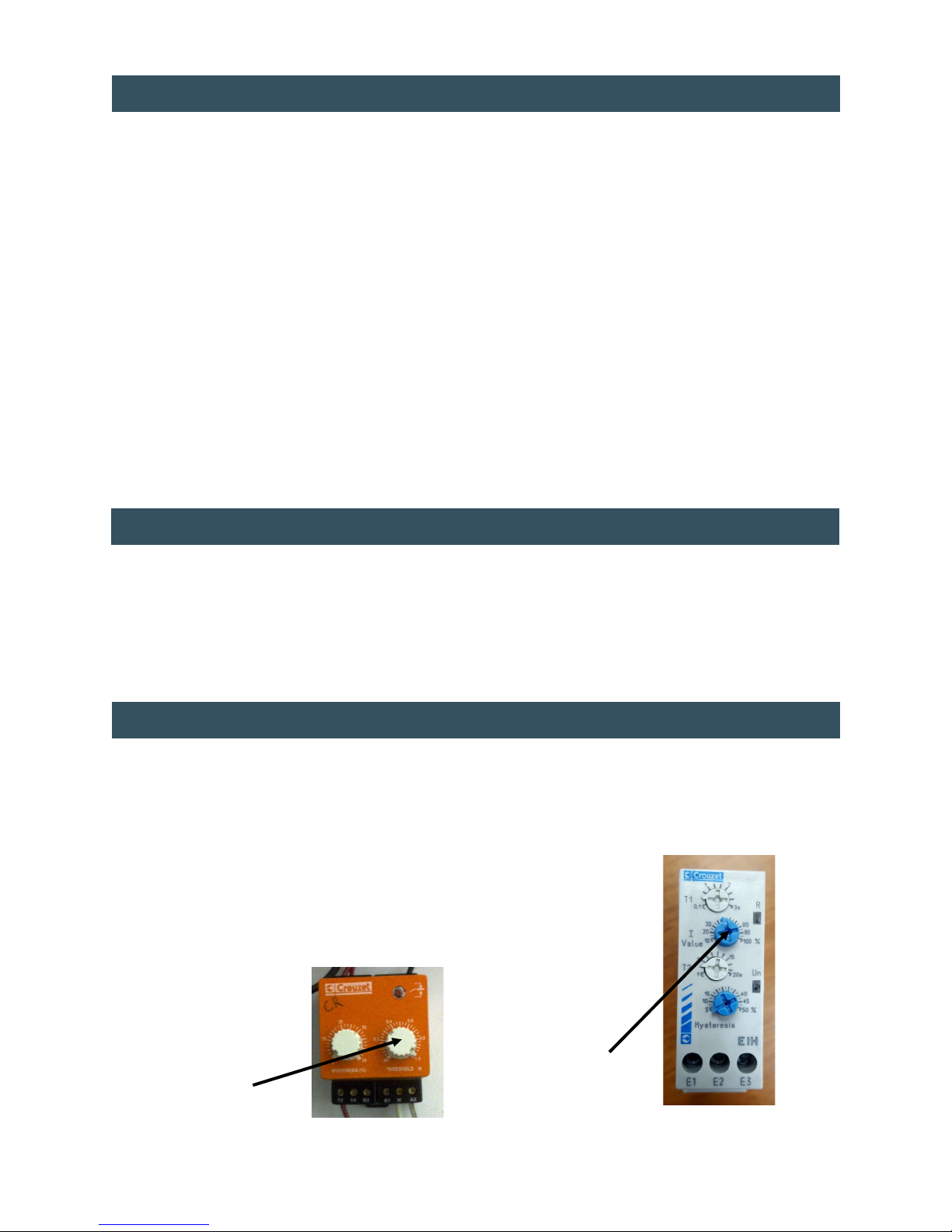
Overload tripping.
Low voltage. Check voltage.
Current relay set too high. See instrucons on previous page.
Motor overheang. Check motor cooling fan for objects
obstrucng air ow.
Cuer-head is dirty or not lubricated Clean and lube.
Defecve or damaged motor. Conduct amperage test. Consult factory
for replacement motor.
Machine will not run in forward but will
run in reverse.
Defecve forward buon. Check contact block for connuity. If bad,
replace.
Disconnected wire on forward buon. Check and reconnect.
Disconnected wire on current relay. Check and reconnect.
Current relay stuck open.
Clean relay. Free up center spool. Check
connuity. If bad, consult factory for
replacement relay.
Machine will not run in reverse but will
run in forward.
Defecve reverse buon. Check for connuity. If bad, replace.
Disconnected wire on reverse buon. Check and reconnect.
Defecve coil in reverse side of contactor. Consult factory for replacement coil.
Shredding capacity is low.
Cuer-head not lubricated. Clean and oil cuer-head.
Low voltage. Check voltage at power supply.
Current relay set too low. See instrucons on previous page.

11
Service Department: 888.270.6879
ALWAYS lock o power rst.
Daily cleaning (Aer 8 hours of operaon)
Remove debris that has built up on the cuers and combers using compressed air (maximum 40 psi) or
vacuum.
Use heavy gloves to remove magnec material from cuer-head.
Visually inspect cuers for damage.
Replace all guards.
Weekly cleaning (Aer each 40 hours of operaon)
Repeat all daily cleaning steps.
Remove debris buildup from base.
Wipe enre machine clean being careful to observe any evidence of oil leaks. Should leakage be observed,
request the aenon of the appropriate maintenance personnel.
Remove all tools, rags, solvents from machine.
Replace all guards.
MAINTENANCE - CLEANING
ALWAYS lock o power rst.
Daily lubricaon (Aer 8 hours of operaon)
Apply light machine oil to cuers.
Weekly lubricaon (Aer each 40 hours of operaon)
Repeat steps from daily lubricaon.
Remove guards.
Apply open gear lube or grease to spur gears.
Replace all guards.
Monthly lubricaon (Aer each 160 hours of operaon)
Repeat steps from weekly lubricaon.
Remove guards
Check reducer oil level. DO NOT OVERFILL.
Grease output conveyor bearings using a mulpurpose
lithium based grease.
Replace all guards.
Annual lubricaon (Aer 2080 hours of operaon)
Repeat steps from monthly lubricaon.
Drain oil from reducer.
Clean magnec drain plug.
Replace drain plug and rell to proper level using a high grade petroleum based, rust and oxidaon inhibited
gear oil.
CE
CAUTION:
Too much oil will cause over heang, and too lile oil will result in gear failure. Check oil level monthly.
Also, under extreme operang condions, such as rapid rise or fall of temperatures, dust, dirt, chemical
parcles, chemical fumes, or oil temperatures above 200° F, the oil should be changed every one to
three months depending on the severity of condions.
MAINTENANCE - LUBRICATION
Spur Gears

12
Service Department: 888.270.6879
REDUCER LUBRICATION
REDUCER BREATHER
& FILL PLUG
REDUCER
BREATHER
& FILL
PLUG
LUBE SCHEDULE
ITEM LUBE FREQUENCY TYPE LUBE
Spur gears Weekly Open Gear Lube (Aerosol)
Reducer Check weekly Gear Oil: High Grade, Petroleum
Based, Rust & Oxidaon Inhibited
Drain and rell yearly (2500 hours)
Cuers Every 4 to 8 hours 10W, 20W, 30W Motor Oil
Output conveyor pulley bearings Monthly Mulpurpose Grease

13
Service Department: 888.270.6879
MAINTENANCE CHECKLIST - DAILY

14
Service Department: 888.270.6879
MAINTENANCE CHECKLIST - WEEKLY

15
Service Department: 888.270.6879
MAINTENANCE CHECKLIST - MONTHLY

16
Service Department: 888.270.6879
MAINTENANCE CHECKLIST - YEARLY

17
Service Department: 888.270.6879
CONVEYOR BELT ADJUSTMENT
ALIGNMENT AND TENSIONING
Read all safety warnings (see page 5) before proceeding.
Lock power o.
Mark the inial posion.
By design, the conveyor belt should have 1/16” or less clearance to side frames. This assists in
prevenng debris from geng under the belt but some side rubbing may be expected. This is
normal.
Loosen jam nuts, each side of machine (see image below).
Ensure all personnel are clear and that no tools are on machine or input chute.
Turn power on.
Run machine in forward.
Stop machine and turn power o.
Adjust alignment by ghtening take-up bolt on side of conveyor where belt is rubbing side frame. Tighten
only one quarter turn at a me.
Tighten jam nuts.
Replace all guards.
Turn power on.
Run machine in forward for ve minutes. If further alignment is required, repeat the above steps.
NOTE:
The belt may stretch during the rst few days of operaon. This will aect alignment since the belt
alignment relies in part on proper tensioning for eecve tracking.
Jam Nut
Take Up Bolt

18
Service Department: 888.270.6879
HD-SSD MODELS
CUTTER HEAD ASSEMBLY - 3/8” & 1-1/2” SHRED WIDTH
ITEM QTY PART # DESCRIPTION ITEM QTY PART # DESCRIPTION
11N/A GEAR BOX: CONSULT FACTORY 20 22 34575 SSD TIE BAR SPACERS
24111907 BEARING 21 233616 DRIVE SHAFT CUTTER
3134592 WEAR BLOCK 22 133617 IDLE SHAFT CUTTER
4134591 WEAR BLOCK 23 133584 DRIVE BEARING BLOCK
5234590 SSD OUTSIDE COMBER 24 133585 IDLER BEARING BLOCK
6134589 IDLER SHAFT 25 133587 HD SINGLE SHAFT SPACER
7134588 DRIVE SHAFT 26 233663 HD DOUBLE SHAFT SPACER
8434586 SSD TIE BAR OUTSIDE SPACER DRIVE SIDE 27 534267 SSD CUTTER STYLE 1
9434584 HD TIE BAR SPACER DRIVE SIDE 28 434268 SSD CUTTER STYLE 2
10 235483 HD TIE BAR SPACER IDLER SIDE 29 634269 SSD CUTTER STYLE 3
11 134463 SIDE PLATE DRIVE SIDE 30 234464 HD OUTER COMBER
12 134462 SIDE PLATE SPUR GEAR SIDE 31 434272 SSD OUTSIDE TIE BAR SPACERS IDLER SIDE
13 134582 END PLATE REDUCER SIDE 32 234275 SSD OUTSIDE SHAFT SPACER
14 134581 END PLATE IDLER SIDE 33 13 34276 SSD SHAFT SPACER
15 134580 DIVIDER SIDE PLATE 34 2110016 SPUR GEAR
16 234579 SSD OUTSIDE COMBER 35 134460 HD SINGLE COMBER
17 434578 COMBER TIE BARS 36 234459 HD DOUBLE COMBER
18 734576 SSD REDUCER SIDE COMBER 37 134845 DIVIDER SPACER
19 634577 SSD IDLER SIDE COMBERS

19
Service Department: 888.270.6879
HD-SSD MODELS
CUTTER HEAD ASSEMBLY - 3/8” & 3/4” SHRED WIDTH
ITEM QTY PART # DESCRIPTION ITEM QTY PART # DESCRIPTION
11N/A GEAR BOX: CONSULT FACTORY 20 133584 DRIVER BEARING BLOCK
24111907 BEARING 21 133585 IDLE BEARING BLOCK
3134592 WEAR BLOCK 22 534267 SSD CUTTER STYLE 1
4134886 WEAR BLOCK 23 434268 SSD CUTTER STYLE 2
5234590 SSD OUTSIDE COMBER 24 634269 SSD CUTTER STYLE 3
6134589 IDLER SHAFT 25 434272 SSD OUTSIDE TIE BAR SPACERS IDLER SIDE
7134588 DRIVE SHAFT 26 234275 SSD OUTSIDE SHAFT SPACER
8434586 SSD TIE BAR OUTSIDE SPACER DRIVE SIDE 27 13 34276 SSD SHAFT SPACER
9134463 SIDE PLATE DRIVE SIDE 28 2110016 SPUR GEAR
10 134462 SIDE PLATE SPUR GEAR SIDE 29 134887 DIVIDER SHAFT SPACER
11 134582 END PLATE REDUCER SIDE 30 3344580 REAR COMBER
12 134581 END PLATE IDLER SIDE 31 434457 FRONT COMBER
13 134580 DIVIDER SIDE PLATE 32 333617 IDLER SHAFT CUTTER
14 134872 SPACER PASS THRU COMBER 33 433616 DRIVE SHAFT CUTTER
15 134579 SSD OUTSIDE COMBER 34 233663 HD DOUBLE SHAFT SPACER
16 434578 COMBER TIE BARS 35 533587 HD SINGLE SHAFT SPACER
17 734576 SSD REDUCER SIDE COMBER 36 634983 TIE BAR SPACER
18 634577 SSD IDLER SIDE COMBERS 37 434984 TIE BAR SPACER
19 22 34575 SSD TIE BAR SPACERS 38 434985 TIE BAR SPACER

20
Service Department: 888.270.6879
HD MODELS
CUTTER HEAD ASSEMBLY - 1-1/2” SHRED WIDTH
ITEM QTY PART # DESCRIPTION ITEM QTY PART # DESCRIPTION
1133584 DRIVE BEARING BLOCK 11 133587 SPACER
2133585 IDLE BEARING BLOCK 12 233663 SPACER
31N/A REDUCER: CONSULT FACTORY 13 233772 SIDE PLATE
4133615 DRIVE SHAFT 14 133772 SIDE PLATE
5233616 DRIVE SHAFT CUTTER 15 233625 END PLATE
6133617 IDLE SHAFT CUTTER 16 2110016 SPUR GEAR
7233619 WEAR BLOCK 17 234464 WEAR BLOCK COMBER
8133618 IDLER SHAFT 18 233740 COMBER WELDMENT
94111907 BEARING 19 133739 COMBER WELDMENT
10 433620 COMBER TIE BARS
This manual suits for next models
6
Table of contents
Other Ameri-Shred Paper Shredder manuals
Popular Paper Shredder manuals by other brands

Dahle
Dahle PaperSAFE 22312 Operating and safety instructions

HSM
HSM Securio B32 operating instructions

Martin Yale
Martin Yale INTIMUS 227-4S Operation instructions

Martha Stewart
Martha Stewart MTS-ELS13 Operator's manual

Fellowes
Fellowes Powershred 280CC operating instructions

Fieldmann
Fieldmann FZD 5015 E user manual