AmeriBrade KAMIMURA TRIDENT User manual

AmeriBrade LLC
Rev-A1 05/05/2022
KAMIMURA TRIDENT MANUAL
2x48 Belt Grinder Setup, Maintenance and Troubleshooting

1 | P a g e
Contents
1. Assemble the Pedestal Stand if you ordered one. Skip to Step 2 if you did not order a Pedestal
Stand. ............................................................................................................................................................2
2. Mount the Grinder Frame to your bench top, or your Pedestal Stand (whichever is applicable). ......3
3. Test your motor for proper forward rotation without a belt by plugging in the grinder and starting
the motor......................................................................................................................................................4
4. Install and Tension a Belt......................................................................................................................5
5. Shut Down.............................................................................................................................................6
6. Maintenance.........................................................................................................................................6
7. Troubleshooting....................................................................................................................................6
Trips Breaker.............................................................................................................................................6
Bogs Down Easily Under Load...................................................................................................................7
Slows Down and Speeds Up Spontaneously.............................................................................................8
Won’t Start................................................................................................................................................9
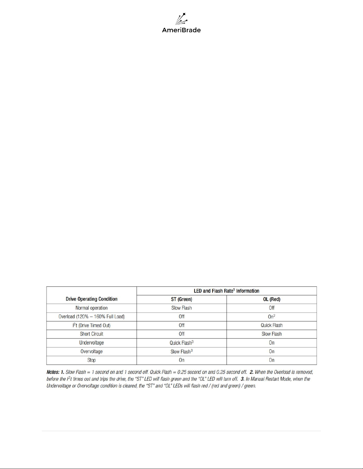
Other VFD Errors.......................................................................................................................................9
Vibration .................................................................................................................................................10
Belt Tracking............................................................................................................................................10
Belt Wobble (Small side to side belt motion) .....................................................................................10
Belt Wander (Large Belt Drifting)........................................................................................................10
Belt Tracks Diagonally Across Platen ..................................................................................................12
Broken Components ...........................................................................................................................12

2 | P a g e
1. Assemble the Pedestal Stand if you ordered one. Skip to Step 2 if
you did not order a Pedestal Stand.
a. Hardware and feet will be included in a small white box labeled as
follows:
b. The 3/8 cap screws require a 5/16 allen wrench
c. The leveling casters use a ¾ wrench or socket
d. Watch this video to see more details about Pedestal Stand Assembly:
https://youtu.be/lMoHw2YIHoQ

3 | P a g e
2. Mount the Grinder Frame to your bench top, or your Pedestal
Stand (whichever is applicable).
a. Where to find the hardware:
i. Bench Top: If you are mounting the grinder to your own
platform, you will need to provide the appropriate length
hardware based on the thickness of your mounting surface.
We suggest 3/8” diameter fasteners.
ii. Direct to Pedestal Stand (no horizontal mount): the hardware
can be found with the rest of the pedestal hardware in a small
bag labeled as follows:

4 | P a g e
3. Test your motor for proper forward rotation without a belt by
plugging in the grinder and starting the motor.
a. If your motor is rotating the wrong direction, contact AmeriBrade for
help with correcting the issue. (760)-998-9602

5 | P a g e
4. Install and Tension a Belt.
a. Disengage the ratchet by pulling in on the finger lever (indicated with
orange arrow below).
b. Add or remove belt tension by lifting or lowering the tension handle
(green arrow below).
c. Spin the belt by hand for 2 to 4 full revolutions in the forward
direction while roughly adjusting the tracking knob as indicated
below to ensure the belt will not collide with the blue frame when
the motor is started
d. Run the motor slowly and re-adjust the tracking until the belt is
accurately centered on the rubber contact wheel.
e. You should now be ready to Grind!

6 | P a g e
5. Shut Down
a. Variable Speed Units:
i. Push the Start/Stop switch down to shut down the machine
and wait for the grinder to slow to a stop. Do not leave the
Fwd/Stop/Rev switch in the center Stop position for extended
periods of time without shutting off the Start/Stop switch. This
may shorten the life of your motor and/or controller.
b. Single Speed Units:
i. Push the large red Stop paddle until there is an audible click
and wait for the grinder to slow to a stop.
6. Maintenance
a. If the grinder will not be in use for extended periods of time, unplug
the machine from power and release the belt tension.
b. Keep threaded components clear of grinding dust to extend their life.
c. Do not store rubber wheels in the sun or against flat surfaces.
Extended time in the sun will degrade the rubber and extended time
against a flat surface may cause flat spots.
7. Troubleshooting
Trips Breaker
•Possible Causes
oThere is a GFI/GFCI somewhere in the circuit. Variable speed units
should not be run on a circuit with a GFI/GFCI anywhere in line.
▪Solution: plug into a circuit that does not contain a GFI/GFCI
oToo long of a run for the wire size supplying the power
▪Solution: Eliminate extension cords and/or use larger wire
oToo small of a circuit breaker. Typically, this is only an issue if the trip
is occurring during heavy grinding. Trips during motor startup are a
sign of a different problem.
▪Solution: Use a minimum 15 amp breaker for 110V units and
minimum 20 amp breaker for 220V units. Also, make sure no
other equipment is using excessive power simultaneously on
the same circuit.

7 | P a g e
Bogs Down Easily Under Load
•Possible Causes
oMaximum Speed is set too high (Variable Speed Units Only)
▪Solution: Turn the MAX trimpot counterclockwise but no lower
than the 10’ o clock position(shown below in 12’ o clock
position): Always make sure the machine is disconnected from
power before opening the speed controller or motor.
oPoor Wiring Connections
Always make sure the machine is disconnected from power before opening
the speed controller or motor
▪Solution: Double check wire connections are tight and making
good contact in the following locations:
•Wires inside the speed controller coming from the
motor or power cord. (Make sure screw terminals are
tight and wires do not pull out of crimped terminal ends)
•Wires inside motor conduit box. (Make sure wires do not
easily pull out of crimped connectors)
•Inside male and female ends of twist-lock-plug between
motor and speed controller. (Open the plug and make
sure individual wires do not easily pull out and make
sure the screws securing the wires are clamping directly
on the copper instead of the outer insulation. Clamping
on the insulation will result in a poor connection)

8 | P a g e
Slows Down and Speeds Up Spontaneously
•Possible Causes
oAcceleration Setting needs tuning (Variable Speed Units Only)
▪Solution: Adjust the ACCEL trimpot in 1/8th turn increments
(maximum ¼ turn each way from original setting). First
clockwise, then counterclockwise. Always make sure the
machine is disconnected from power before opening the speed
controller or motor
oDeceleration Setting needs tuning (Variable Speed Units Only)
▪Solution: Adjust the DECEL trimpot in 1/8th turn increments
(maximum ¼ turn each way from original setting). First
clockwise, then counterclockwise. Always make sure the
machine is disconnected from power before opening the speed
controller or motor

9 | P a g e
Won’t Start
•Possible Causes
oBreaker is Tripped
▪Solution: Reset Breaker. If problem persists, see “Trips
Breaker” section above
oFwd/Stop/Rev switch is set in the center “Stop” position (Variable
Speed Units Only)
▪Solution: Make sure a direction is selected by pushing the
Forward/Reverse Switch up for forward or down for reverse
oStart/Stop switch is not being pushed all the way into the start
position
▪Solution: Push the Start/Stop switch up after the fwd/stop/rev
switch is in the fwd or rev position
oStart button on Start/Stop paddle switch is not being pushed all the
way (Single Speed Units Only)
▪Solution: Push the green start button hard enough to cause an
audible click
Other VFD Errors
1HP DRIVE OPERATING CONDITION AND STATUS LED INDICATOR
LED INDICATORS ARE ONLY VISIBLE WITH THE COVER REMOVED

10 | P a g e
Vibration
•Diagnosis/isolation
oRun the motor without a belt to see if the source is at the motor or
drive wheel.
oIf available, try a different small wheel
oIf the vibration source is not the motor or the small wheel, it may be
the tension wheel or rubber contact wheel. Inspect each for signs of
wear or damage.
oContact AmeriBrade to discuss the results of these experiments and
to possibly replace worn/defective wheels
▪(760)998-9602
Belt Tracking
Belt Wobble (Small side to side belt motion)
oBelt wobble is normal and varies between belts. It is due to the
accuracy of the belt manufacturing process. Surface Conditioning
(Scotch-Brite) and Leather belts will exhibit extreme amounts of belt
wobble. Double check the other belt tracking problems below to
make sure there is not another issue exaggerating the wobble.
Belt Wander (Large Belt Drifting)
oPossible Causes
▪Low Belt Tension
•Solution: lift the tension handle with a moderate
amount of force (roughly 10 lbs or more) to take out
excessive belt slack.
▪Worn Wheels
•Solution: Replace wheels that show signs of
asymmetric/tapered wear.
▪Loose Tracking Mechanism
•Make sure the tracking knob exhibits some resistance to
turning. If it turns too freely, loosen the shaft collar on
the stud of the tracking knob with a 7/64” allen wrench.
Turn the tracking knob counterclockwise several
rotations until the spring washers between the knob and
the outside of the blue frame begin to bind and

11 | P a g e
compress (see image below for reference). Hold the
shaft collar tight against the inside of the blue frame and
re-tighten it with the 7/64” allen wrench. Turn the
tracking knob clockwise to return the small wheel holder
to a neutral position and use caution when running a
belt for the first time to make sure the belt tracking is
properly centered.
•Make sure the small wheel holder does not display any
free movement when pushed by hand. If there is free
play and the tracking knob is already tensioned as
described in the previous step, make sure all of the
fasteners indicated below are tight in the small wheel
holder (mating parts hidden for visibility)

12 | P a g e
▪Vibration can also cause the belt to wander
•Solution: Isolate the source of the vibration and
eliminate it. See “Vibration” Section above
Belt Tracks Diagonally Across Platen
oPossible Causes
▪Replaceable platen plate needs adjustment
•Solution: with a belt installed and centered on the
contact wheel, use a 7/16” wrench to loosen the 2
screws holding on the replaceable platen plate and
adjust it until the edge aligns with the edge of the belt.
Re-Tighten the 2 screws.
Broken Components
Contact AmeriBrade to replace damaged components.
Call: (760)998-9602
Email: info@ameribrade.com
Shipping:
AmeriBrade LLC
6988 Bandicoot Trl
18-682
Oak Hills CA, 92344
Table of contents
Popular Grinder manuals by other brands

Chicago Pneumatic
Chicago Pneumatic CP3450 Operator's manual

Metabo
Metabo W 18 LTX 115 Quick Operating instruction

Metabo HPT
Metabo HPT G 12SA4 Safety instructions and instruction manual

Dynabrade
Dynabrade 65750 instruction manual

Klutch
Klutch NT18G Operator's manual

Makita
Makita DGA512ZU instruction manual