American Dish Service ASQ User manual

American Dish Service
INSTALLATION INSTRUCTIONS
Model ASQ Glasswasher
Available in 75-second cycle
Undercounter, Carousel, Chemical Sanitizer, Batch-type Glasswasher
Listed by UL #E68594, NSF/ANSI 3, LATest Labs File M-810115, Mass. License P3-0111-306
If you have questions, call 800-922-2178 or visit our website at www.AmericanDish.com
1
The electrical power supplied to this machine is an imminent hazard that could result in severe
bodily injury or death if not properly installed or hooked up correctly. When working in the control
box or on electrical parts, always disconnect power and tag-out before servicing. Replace cover
to control box and other protective covers when finished servicing this equipment.
Copyright ADS Installation Manual Model ASQ, Revision 2.0, 6/7/2013
Total Restaurant Supply - https://totalsupply1.com - Toll Free 1-800-944-9304 - Local 507-288-9454
2940 Hwy 14 W, Rochester, MN 55901

2
READ Manufacturer’s Manual before Using this Product. For your safety read and observe all
cautions shown throughout these instructions. While performing installations described in this
booklet, wear approved Personal Protective Equipment, including Safety Eye-Wear.
CHEMICALS— There are potentially hazardous situations when working with industrial cleaning
chemicals for dishmachines. See chemical manufacturer’s safe practices and MSDS sheets for
handling and installing chemicals and supply containers.
#1 BEFORE YOU BEGIN — American Dish Service provides this information as a service to our
customers. Keep all instructions for future reference. ADS reserves the right to alter or update
this information at any time. Should you desire to make sure that you have the most up-to-date
information, we would direct you to the appropriate document on our web site:
www.americandish.com. Set out below are the specifications and requirements that you must use
and follow to properly install the type or types of equipment listed above. It is your obligation as
the customer to ensure that the machine is installed safely and properly, and when completed,
the machine is left in proper and safe working order. Electrical, Plumbing, and Chemical hookup
should be performed by a qualified professional who will ensure that the equipment is installed
in accordance with all applicable Codes, Ordinances, and Safety requirements. Failure to follow
the installation instructions could void the warranty. ADS assumes no liability or control over the
installation of the equipment. Product failure due to improper installation is not covered under the
ADS Warranty.
#2 FLUSH OUT— Do not install spray arm until machine is flushed with water. When this machine
is turned on, push the FILL switch to put water in the tank then push the button on the front door
to complete one cycle. Do this before installing the spray arm. Pump the flush water out before
installing spray arm by pushing the switch marked DRAIN. Draining the water will flush the tank
and pump.
#3 WATER HEATERS — or boilers must provide the minimum temperature of 120°F required by
the machine listed above, which has a minimum demand of 57.6 gallons per hour. The
recommended temperature range for optimal performance is 130-140°F. These specifications are
for the glasswasher only, which typically accounts for only part of a restaurant’s hot water
demand.
#4 IMPORTANT— The model of glasswasher listed in this document must be installed with space
around the outside to allow for servicing as well as a 4” space behind the machine from the wall.
It should not be built into wooden cabinets.
#5 INSPECT FOR DAMAGE — If you receive a damaged machine, do not sign “Clear” but write
“Damaged” on the documents.
#6 LOOSE ELECTRICAL CONNECTIONS — Damage to equipment can occur if the following
precautions are not observed. Before connecting power to the machine, check all electrical
terminals in the control box. Screws can loosen in transit.
Copyright ADS Installation Manual Model ASQ, Revision 2.0, 6/7/2013
Total Restaurant Supply - https://totalsupply1.com - Toll Free 1-800-944-9304 - Local 507-288-9454
2940 Hwy 14 W, Rochester, MN 55901

3
ELECTRICAL SECTION
Loose connections on high amp load terminals such as the pump motor will cause wire burning
and component damage during operation and will not be covered under ADS warranty.
#7 “CLEAN CIRCUIT” means the electrical circuit breaker for the glasswasher supplies no other
outlets, machines, or lights. GFCI outlets are not recommended for commercial glasswashers;
ADS recommends that a single-rack machine be installed with the wire connection (hard-wired)
directly from the circuit breaker. If a plug and socket are used to provide electrical power to a
glasswasher in a commercial kitchen, then according to electrical code it must be a GFCI, but not
all GFCIs are the same. They must be rated for the draw of the circuit.
Reference NEC Article 210.8 GFCI Protection (B) Other Than Dwelling Units (2) Commercial and
Institutional Kitchens. All 15 and 20A, 125V receptacles installed in kitchens, even those that do not
supply the countertop surface, must be GFCI protected.
#8 This equipment is considered an item of heavy use. It is not rated for outdoor use.
Electrical—ASQ, w/350w Sustainer Heater (120 volt, 15 amp)
A time cycle of 72-seconds is the timer available for this model and is compliant with NSF listing.
Showing controls on lower access door ASQ control box with cover removed
The power supply for 120 volts, 15amps, shall consist of two #12-14-gauge wires and one suitable green
ground wire. The 15 amp breaker or 15 amp fuse must be on a clean circuit for only this machine. On
the left-hand side of the lower cabinet is junction box with a 7/8” hole for the 1/2” conduit that will bring the
building’s electrical power to the machine. This junction box is behind the inspection door.
Remove the junction box cover, attach the conduit and connect a black 120 volt supply wire to the black
wire in the junction box. Connect a white neutral supply wire to the white wire in the junction box. When
powered up, test the neutral wire to a ground source with a voltmeter, it should read 0 to 6 volts. Test the
black wire to a ground source, it should read 110-120 volts. Attach a building ground wire to the green
ground screw located in the junction box and tighten all wires. Replace the junction box cover.
Copyright ADS Installation Manual Model ASQ, Revision 2.0, 6/7/2013
Total Restaurant Supply - https://totalsupply1.com - Toll Free 1-800-944-9304 - Local 507-288-9454
2940 Hwy 14 W, Rochester, MN 55901

4
Copyright ADS Installation Manual Model ASQ, Revision 2.0, 6/7/2013
Relays, counter, switches, cam timer, motor
contactor Optional buzzer for low chem. alarm
Power junction box for incoming 120v power Wash motor contactor and motor relay
Heater terminals on right rear side of the tank Pump motor, black wires to float can be seen
upper left
THE SUSTAINER HEATER— is rated 350 Watts at 120v, and will draw approximately 3 amps. It is not
designed to provide operational heat; the operational hot water must be provided by the building’s primary
water heater. The sustainer heater will not provide a rise to the incoming water temperature. Its purpose
is to sustain the existing hot water sitting in the pan of the machine if it were to sit idle for periods of time.
The sustainer snap action thermostat receives power any time the machine is switched on.
IT IS RECOMMENDED THAT THIS EQUIPMENT BE INSTALLED USING A NEW CIRCUIT BREAKER.
This machine does not use a booster heater.
Total Restaurant Supply - https://totalsupply1.com - Toll Free 1-800-944-9304 - Local 507-288-9454
2940 Hwy 14 W, Rochester, MN 55901

5
PLUMBING SECTION
Copyright ADS Installation Manual Model ASQ, Revision 2.0, 6/7/2013
#1 TANKLESS water heaters can be problematic for commercial dishmachines and glasswashers.
The ADS model ASQ glasswasher requires the full cycle amount of water (1.2 gallon) supplied
within 7 seconds. It has been the experience of ADS that tankless supply systems require
multiple units plumbed in sequence with a recirculation loop to achieve proper pressure and
temperature.
Check with the tankless water heater manufacturer, they may recommend a storage tank to
guarantee proper flow and line pressure to the machine. Failure to provide adequate water
quantity, pressure and temperature to the machine will cause the machine to function
improperly and is not the responsibility of ADS. Improperly installing ADS equipment in this
manner could void the warranty. All costs associated with providing an adequate water supply to
the machine is the sole responsibility of the user.
#2 HOODS — Follow all local plumbing and mechanical codes. IMC 2012, section 507.2.2 requires
Type II hoods for all commercial ware-washers except where the heat and moisture loads are
incorporated into the building’s HVAC systems or dishwashing equipment designed with separate
heat and moisture removal systems. An undercounter-type, chemical sanitizing dishwasher is
rated at 6450 Btu/h by table 5E, ASHRAE Research Project #1362, 8/5/2008. ADS DOES NOT
SPECIFY BUILDING HVAC VALUES.
#3 DRAIN SIZE — The pump motor will reverse and pump tank water through a ¾” hose to the
white plastic drain manifold. From there the drain water falls by gravity to the building drain. The
plastic drain line is 1.5” diameter tube. THIS MODEL WILL NOT PUMP THE DRAIN WATER FROM
THE MACHINE.
#4 CONTROL FLOAT—The control float is located inside the tank on the bottom to the left of the
pump, it prevents the machine from starting without sufficient water. Water flow issues will delay
cycle until control float senses sufficient water in the tank. The float is secured on the float stem
by a retaining clip. The stainless float has an “O” stamped on the end that should be on top. The
glasswasher will not start if the float is installed upside down or missing.
Showing ½” H2O solenoid, also plastic drain tube Hot water inlet at ½” elbow
Total Restaurant Supply - https://totalsupply1.com - Toll Free 1-800-944-9304 - Local 507-288-9454
2940 Hwy 14 W, Rochester, MN 55901

6
Hot Water Connection
Copyright ADS Installation Manual Model ASQ, Revision 2.0, 6/7/2013
WATER HEATER — Flush the building’s water lines before connecting to the machine. Prior to
connecting plumbing, level the machine by adjusting the feet at the bottom of each leg up or down.
Water heaters or boilers must provide the minimum temperature of 120°F required for this model of
machine, which has a minimum hourly demand of 57.6 GPH for ASQ. Temperatures above 150°F exceed
the operational design limits for this model. This model cannot be converted to high temp sanitizing by
adding a booster.
Control float, “O” mark should be on top
INLET FLEX HOSE—Domestic style 1/2” flexible braded hose should not be used to connect the
glasswasher. The ID of the plastic liner for this type hose restricts flow. The minimum size for water
connection is ½” pipe.
ADS provides a 48” stainless flex hose that has large enough ID for adequate flow with P/N 088-1068. To
use copper pipe plumbing, connect 1/2" male pipe thread (1/2” is the minimum allowable pipe size) of the
hot water supply line to the 1/2" female pipe thread on the machine’s water inlet manifold.
SINK FAUCET — If the hot water line is also supplying the faucet of a pre-rinse sink, install check valves
on both cold and hot water inlets to the faucet — to avoid cooling the water by cross-connection in the
mixing head of the faucet. The hot water inlet manifold is located behind the access door and to the lower
right. The supply water must have a minimum of 120°F , but 130-140°F is recommended for best results.
Water Pressure for Filling
Minimum pressure needed at the machine is 15 psi DURING the fill. This is called FLOW pressure.
STATIC pressure readings can be misleading and can drop to “0” during fill. With flow pressures below
15 psi, additional measures will be needed to resolve the problem. The first suggestion is to run 3/4" pipe
directly from the water heater to the glasswasher. If the problem persists, install a pressure bladder tank
used for domestic well water; a 5 gallon size would be a minimum, 10 gallon as a maximum.
Total Restaurant Supply - https://totalsupply1.com - Toll Free 1-800-944-9304 - Local 507-288-9454
2940 Hwy 14 W, Rochester, MN 55901

7
Copyright ADS Installation Manual Model ASQ, Revision 2.0, 6/7/2013
Drain Requirements (Gravity Drain)
Follow local codes and ordinances
Do not exceed 5 feet distance to drain.
Drain line is 1 1/2” O.D.
Glasswasher drain (1 1/2” plastic tube) protrudes through the bottom of the cabinet floor on the right front
corner (drain is directly in front of the water inlet connection). This drain can be rotated to either side.
Drain lines must be 1 1/2” or larger. Do not use adapters to reduce the drain line. Do not plumb with tight
elbows or 180° bends.
CHEMICAL FEEDERS SECTION
You must wear approved safety eye-wear before connecting chemicals. Read the chemical
manufacturer’s MSDS sheets. Chemicals can damage or corrode plumbing and stainless parts of
the dishmachine. Do not run chemical lines over controls or plumbing. Always secure chemical
lines and check regularly for leaks. If not properly handled, chemicals can cause serious bodily
injury. In the event of chemical contact to skin or eyes; wash immediately with fresh water and
seek medical attention.
Showing deter, rinse, sanitizer internal chemical
pumps Chlorine test strips for measuring sanitizer
Total Restaurant Supply - https://totalsupply1.com - Toll Free 1-800-944-9304 - Local 507-288-9454
2940 Hwy 14 W, Rochester, MN 55901

8
Copyright ADS Installation Manual Model ASQ, Revision 2.0, 6/7/2013
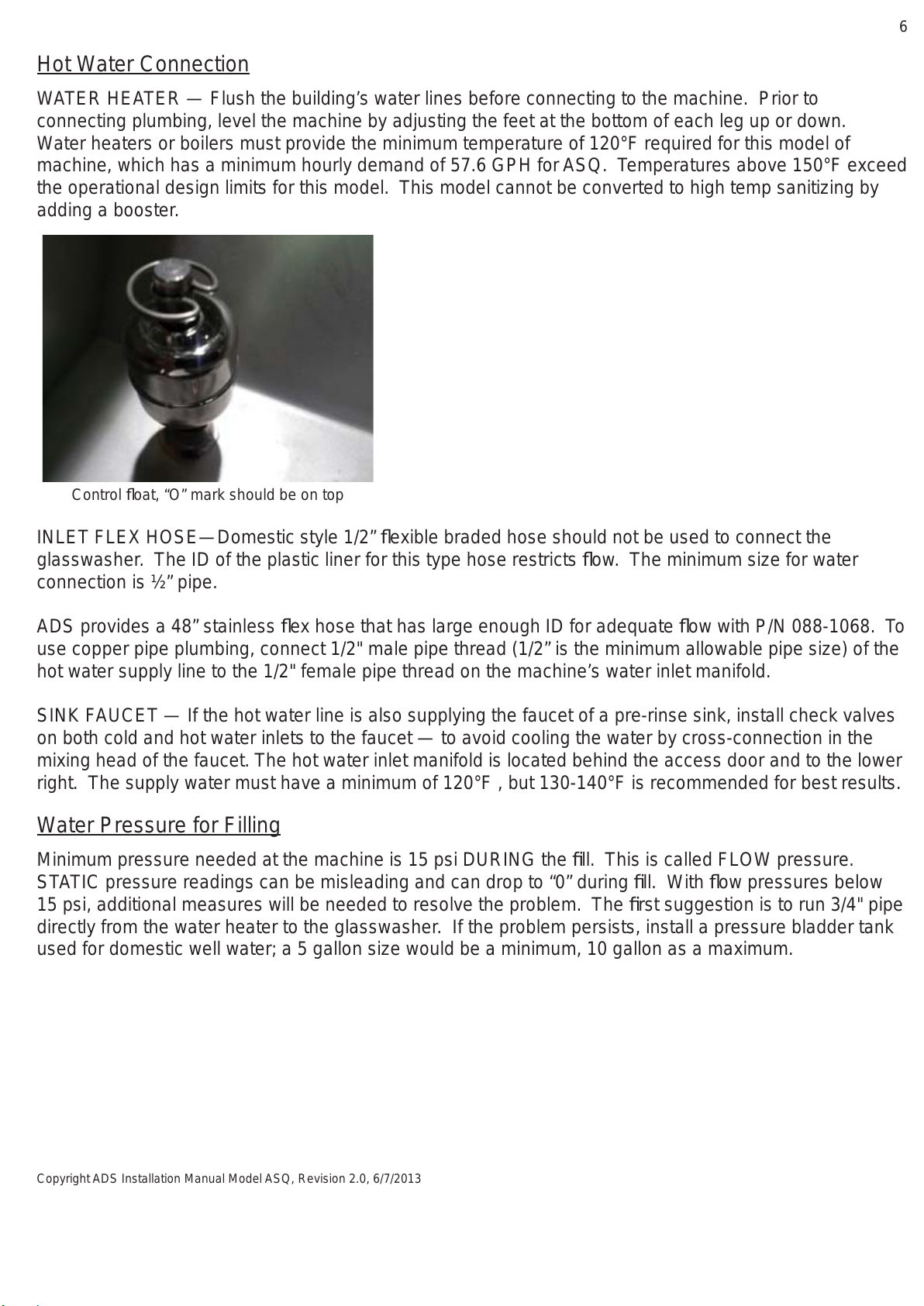
ADS provides three (3) peristaltic pumps to dispense liquid chemicals
Chemical feed lines are color coded “Red” Detergent, “Green” Sanitizer, “Blue” Rinse-aid
Pick-up tubes are provided for chemical product containerers
Sanitizer (chlorine) concentrations shall be set at 50 parts per million
Inspect the transfer tubing for any cuts or holes, keep them protected and secured out of the way
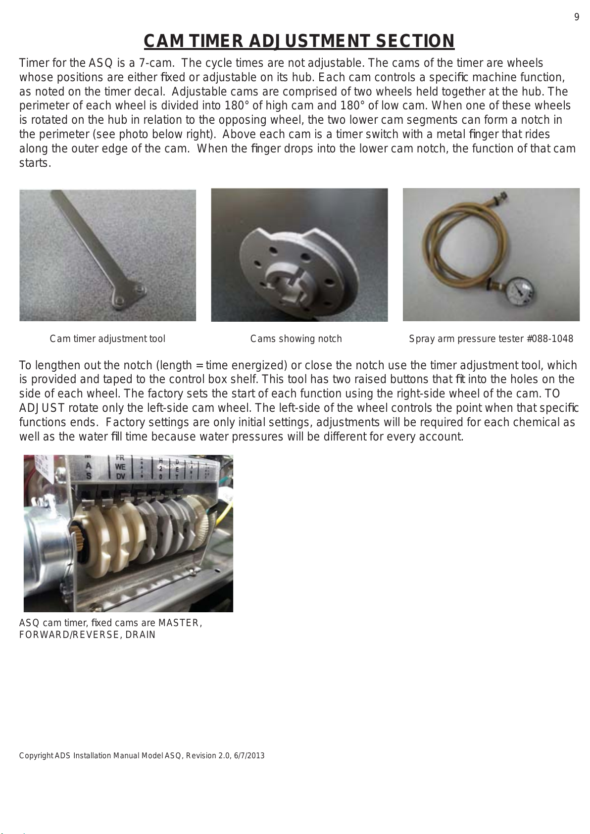
Showing chemical lines and temp gauge in
cabinet Optional Chemical Alarm switch, barb with
adjusting screw *
TYPE OF CHEMICALS — Use only commercial grade low-energy chemicals. For proper operation, use
non-foaming detergents and buffered sanitizer. Do not wash gold, pewter, silver, or silver-plate with
chlorine based sanitizers. High concentrations of chlorine sanitizers and caustic detergents will cause
damage to metals and welds. Do not exceed 50 parts-per-million (PPM) “free” or available chlorine, using
higher than 50 ppm will be dependent on local health requirements, however, the increased chlorine will
result in higher corrosion of metal parts. The resulting damage from overusing chlorine is not
covered under the ADS warranty. Purpose-built ware-washing dispensers are needed to properly meter
chemicals for wash and rinse. These dispensers are included with this model. Manually adding industrial
chemicals to the machine is unsafe and not approved.
CHEMICAL LINES — Place color coded tubes into proper chemical containers. The containers of one
gallon each are placed inside the lower cabinet. On the side of the control box door, there are
chemical prime switches. There is a decal identifying each switch. To prime chemicals, use these
momentary switches, verifying that all three pumps rotate. If a chemical pump squeeze tube has taken a
set (not allowing the pump to turn), manually free the pump by pulling on the discharge side (right-hand)
of the squeeze tube while pushing the prime switch. Squeeze tubes should be replaced at least every six
months.
CHEMICALADJUSTMENT— Chemical dispensing is controlled by a mechanical cam timer. All chemical
products must be adjusted for the product’s concentration and local water conditions. It will be necessary
to adjust initial factory settings (See page 9 for Cam Timer Adjustment Section). Water softeners should
be added to correct hard water conditions. Hard water is often treated with more expensive ware-washing
chemicals, but it is more effective and less destructive to the metal to soften the water before it comes to
the machine.
AUDIBLE CHEMICALALARM OPTION —The optional chemical alarm (P/N 031-0326) uses a pressure
switch with a barb fitting that extends from the control box and connects to the chemical line by means of
a “t” fitting. The switch sends voltage to a buzzer located in the control box. Sensitivity is adjusted by an
Allen wrench (5/64” or 2mm) to turn a screw located in the center of the barb (see photo above*).
Remove the tube from the barb; turn the screw to the right for less sensitivity. Chemical must be placed
on the floor of the cabinet for the pressure switch to work
Total Restaurant Supply - https://totalsupply1.com - Toll Free 1-800-944-9304 - Local 507-288-9454
2940 Hwy 14 W, Rochester, MN 55901

9
Copyright ADS Installation Manual Model ASQ, Revision 2.0, 6/7/2013
CAM TIMER ADJUSTMENT SECTION
Timer for the ASQ is a 7-cam. The cycle times are not adjustable. The cams of the timer are wheels
whose positions are either fixed or adjustable on its hub. Each cam controls a specific machine function,
as noted on the timer decal. Adjustable cams are comprised of two wheels held together at the hub. The
perimeter of each wheel is divided into 180° of high cam and 180° of low cam. When one of these wheels
is rotated on the hub in relation to the opposing wheel, the two lower cam segments can form a notch in
the perimeter (see photo below right). Above each cam is a timer switch with a metal finger that rides
along the outer edge of the cam. When the finger drops into the lower cam notch, the function of that cam
starts.
Cam timer adjustment tool Cams showing notch Spray arm pressure tester #088-1048
To lengthen out the notch (length = time energized) or close the notch use the timer adjustment tool, which
is provided and taped to the control box shelf. This tool has two raised buttons that fit into the holes on the
side of each wheel. The factory sets the start of each function using the right-side wheel of the cam. TO
ADJUST rotate only the left-side cam wheel. The left-side of the wheel controls the point when that specific
functions ends. Factory settings are only initial settings, adjustments will be required for each chemical as
well as the water fill time because water pressures will be different for every account.
ASQ cam timer, fixed cams are MASTER,
FORWARD/REVERSE, DRAIN
Total Restaurant Supply - https://totalsupply1.com - Toll Free 1-800-944-9304 - Local 507-288-9454
2940 Hwy 14 W, Rochester, MN 55901

10
Copyright ADS Installation Manual Model ASQ, Revision 2.0, 6/7/2013
Adjustable cams are colored either black or gray
ASQ Glasswasher Cam Timer Adjustment
Timer 75 second - 7 cam, cycle time is not adjustable
#1 Cam: The white cam on your left is the master cam. It controls the total time of the cycle and is not
adjustable.
#2 Cam: This white cam is the motor reversing cam. It is not adjustable.
#3 Cam: This white cam controls the drain time. It is not adjustable.
#4 Cam: The H2O or FILL cam opens the water solenoid. Too little water causes the pump to surge.
Overfilling does not allow all the water to drain between cycles, causing carry-over. Adjust only the left-side
of cam wheel, set the cam to close the water solenoid when the glasswasher reaches full spray arm
pressure of 9 psi.
#5 Cam: This black or gray cam controls detergent. It is adjustable
#6 Cam: This black or gray cam controls sanitizer. It is adjustable. Set the sanitizer concentrations at 50
ppm
#7 Cam: This black or gray cam controls rinse additive. It is adjustable.
TUNING A BATCH-TYPE MACHINE SECTION
Tuning is essential for proper cleaning; do not skip this IMPORTANT PROCEDURE
The key to understanding proper tuning is to realize that the drain sequence cannot be changed. It is a
fixed time function and the regulator of the cycle between wash and rinse. Therefore, all tuning is
accomplished by setting or adjusting the fill cam in relationship to the fixed drain cam. The goal of tuning is
to eliminate all soiled wash water through the drain, before the drain period ends.
It is at this point that the H2O (FILL) cam should be adjusted so the water solenoid turns the fill water on.
That function is controlled by the adjustment of the fill cam. For optimum results, allow the fill water to
flush the interior of the machine for a few seconds before the drain finishes. Once the drain ends the fill
cycle begins. Fill must continue until full spray arm pressure is reached. This can be verified with the use of
a spray arm pressure tester (Kit #088-1048) attached where one of the end plugs are usually screwed into
the wash arm. The tester gauge will indicate full spray arm pressure when the needle stops fluctuating and
remains steady. Adjust the fill cam to turn the water OFF when this point of steady pressure is reached. It
is important that the machine is not overfilled. Use just enough water to reach Full Spray-arm Pressure
(FSP), no more than that is needed for proper operation.
72-second timer operation of ASQ [Pump shut off]-[*sanitizer here]
START [------WASH 40-Seconds----------------] - [--DRAIN 14-Sec--] - [--21-sec to FILL and RINSE---] END
[*detergent here] [-Fill until FSP is reached-]
If a pressure gauge tester is not available, an approximation of full spray arm pressure could be
determined by the sound of the spray arm. There would be a typical continuous swishing sound of the
water spraying. Again, when this sound is heard, that would be the point to turn the water OFF. Seven
seconds of full spray arm rinse pressure is required by health code. Operating temperature of 120°F is
the minimum, 130-140°F is recommended.
Total Restaurant Supply - https://totalsupply1.com - Toll Free 1-800-944-9304 - Local 507-288-9454
2940 Hwy 14 W, Rochester, MN 55901

11
Copyright ADS Installation Manual Model ASQ, Revision 2.0, 6/7/2013
FINAL INSTALLATION CHECK LIST
Do not rotate the carousel while machine is in cycle. Doing so could result in serious bodily injury
from spraying hot water and chemicals.
Cycle light, master switch, chemical sight window,
start switch
1) Check to be sure the power is OFF. The master switch is the black switch located on left front of the
glasswasher. To turn the switch off, twist a quarter turn to the left.
2) Remove all the packaging and the three glassware retainers from the carousel. Glass retainers are wire
forms that locate glassware away from the corners. Push a glass retainer into each carousel compartment
Save all instructions for future reference.
3) Remove the protective film if present from the front panel, the hood, or other surfaces.
4) Verify 2” clearance between the glasswasher top and bottom of the countertop overhang. This is
needed for cleaning breakdown. Overhangs cannot extend past the center of the carousel.
5) Turn on the water supply. Check for leaks. Tighten any connections if needed.
6) To operate, turn on the main power circuit breaker and turn the glasswasher master switch to the “ON”
position by turning it a quarter turn to the right.
7) Before operating machine, remove the spray arm and manually fill the machine with water using the fill
switch (FILL). The switch is located on the side of the control box. Run one complete cycle by pushing the
red start switch on the front of the door. This is the flush cycle, which removes installation debris from the
wash tank and the pump. After flushing, re-install the spray arm. Failure to follow this procedure can
damage spray arm pivot and is not covered under the ADS warranty.
8) Observe the water level decal. This decal is located behind the door, marked with a black line, on the
clear vinyl hose connected to the drain plumbing. This mark is the approximate level for proper fill.
9) Verify incoming water temperatures 120°F minimum (130-140°F recommended).
10) Verify that chemical feed lines are in their proper container and that lines are primed. Prime switches
are located on side of the control box and labeled.
Total Restaurant Supply - https://totalsupply1.com - Toll Free 1-800-944-9304 - Local 507-288-9454
2940 Hwy 14 W, Rochester, MN 55901

12
Copyright ADS Installation Manual Model ASQ, Revision 2.0, 6/7/2013
Carousel is rotated manually, shows correct
position for cycle ASQ tank scrap tray with spray arm above
OPERATING INSTRUCTIONS
The carousel is divided into three positions by stainless steel panels. These panels isolate each
compartment, controlling the water and washing action of the rotating spray. With a push of the detent
lever, the carousel easily rotates and locks into the next position. While one section of the carousel is being
washed, the operator can unload the cleaned glassware from the second section, then load dirty glassware
into the last section of the carousel.
TO OPERATE — completely load the first compartment or section of carousel. Note: Failure to load
complete sections can cause breakage of tall stemware. Release the carousel by pushing the detent
latch to the left. This latch is located in the front between the carousel and the glasswasher cabinet.
MANUALLY TURN — the carousel until the loaded glasses are in the washing compartment . Proper
alignment is indicated when the detent pushes into the notch.
START THE CYCLE — by pushing the red start switch on the front of the glasswasher. The switch stays
illuminated during operation. Wash, Rinse, and Sanitization occurs in 75 seconds.
Latch located between the carousel and the
glasswather cabinet.
Total Restaurant Supply - https://totalsupply1.com - Toll Free 1-800-944-9304 - Local 507-288-9454
2940 Hwy 14 W, Rochester, MN 55901

13
Copyright ADS Installation Manual Model ASQ, Revision 2.0, 6/7/2013
Once the hood top and the carousel are removed, the operator has easy access to the splash shields, the
spray arm, the scrap tray, and the pump screen. Remove the splash shields under the carousel (triangular
shaped) by lifting up on the innermost edge, then slide the shield towards the center. The spray arm lifts off
of the spray arm pivot. Once the spray arm is removed, the scrap tray can be lifted out by the handles and
the circular pump screen will slide up, off the pump housing. Important:Always visually inspect tank for any
broken glass before removing pump screen.
TO CLEAN: Unscrew the end plug from the spray arm tube. Clear plugged spray jets by pushing a
toothpick into the jet. The spray arm will not turn if the jets are plugged. Flush debris from the spray arm
by rinsing under a faucet and replace the endplugs. Clean the scrap tray and the pump screen by flushing
with water. Caution: Do not hit the scrap tray against a trash can. After cleaning, reassemble in reverse
order.
PUMP SEAL and IMPELLERS For Reversing pump
Showing pump screen Diffuser w/spray arm pivot Diffuser removed, centrifugal Impeller
WARNING: Glass Breakage can occur - always visually inspect tank for sharp shards of glass
before breakdown.
TO DRAIN — Drain water from the tank using the drain switch marked (DRAIN), located on the side of the
control box. The control box is mounted on the inside of the door.
Remove the hood top by lifting up approximately one (1”) inch and slide the hood top toward the front.
Remove the carousel drum by lifting up 1 1/2” until the carousel has cleared the pivot pin, then pull it out
and towards the front. The pivot pin is attached to the top center of the cabinet.
BREAK-DOWN AND CLEANING FOR DAILY MAINTENANCE
Total Restaurant Supply - https://totalsupply1.com - Toll Free 1-800-944-9304 - Local 507-288-9454
2940 Hwy 14 W, Rochester, MN 55901

14
Copyright ADS Installation Manual Model ASQ, Revision 2.0, 6/7/2013
Drain axial propeller, o-ring on shaft Ceramic seal pressed into propeller Graphite seal pressed into pump base
2 Spacer washers under propeller Small o-ring on top of propeller Large o-ring in top of impeller
APPENDIX
089-9391---ASQ Parts Manual
089-9348---ASQ Service Manual
089-9303---Brochure
089-9441---Wall Chart
089-9444---Wire Diagram
089-9359---Spec Sheet
089-9381---ASQ Installation Manual
Impeller removed from housing Suction plate, housing removed Drain inlet plate, w/alignment screw
Total Restaurant Supply - https://totalsupply1.com - Toll Free 1-800-944-9304 - Local 507-288-9454
2940 Hwy 14 W, Rochester, MN 55901

15
Copyright ADS Installation Manual Model ASQ, Revision 2.0, 6/7/2013
Total Restaurant Supply - https://totalsupply1.com - Toll Free 1-800-944-9304 - Local 507-288-9454
2940 Hwy 14 W, Rochester, MN 55901

16
Copyright ADS Installation Manual Model ASQ, Revision 2.0, 6/7/2013
purple
pink
Yellow
Brown
white
Black
Purp
BRN 29
OG 68 GR 73 BU 78
PINK BAR
WHITE BAR
GN 12
BK 6
BN 20
PK 7 YW 8
BK 57
PK 28
BN 29
WHITE
WHITE
WHITE
WHITE
WHITE YW 34
BN 23
PUP 31
DRAIN SWITCH
FILL SWITCH
START SWITCH
HOOK-UP FOR
115v, 20a, 60Hz POWER
MASTER SWITCH
CAM TIMER
CYCLE COUNTER
MTR RELAY
PUMP
FLOAT
HEATER
FILL VALVE
19
999
9
9
N/OPEN
N/OPEN
N/CLOSED
N/CLOSED
POWER
POWER
COIL
COIL
PRIME RINSE
PRIME SANI
DETERGENT SANITIZER RINSE AID
START RELAY
RESUME RELAY
WHITE
BU 78
GR 73
OG 68
BU 26 BN 25
PUP 65
PUP 65
WH65
PK 82
WH84
PUP 61
OG 16
BU 14
PUP 13 BLACK
RD 77
ORG 16
PUP 13
GRN 12
BLK 6
BLU 14
ORANGE- 17 IS REVERSE (DRAIN)
BLUE - 14 IS FORWARD (PUMP)
BLACK - 6 IS POWER
GND
brown
orange
Purple
green
pink
Purple
Green
Orange
Red
Brown
MOTOR CONTACTOR
white
Pink
yellow
Blue
Total Restaurant Supply - https://totalsupply1.com - Toll Free 1-800-944-9304 - Local 507-288-9454
2940 Hwy 14 W, Rochester, MN 55901
Other manuals for ASQ
2
Table of contents
Other American Dish Service Dishwasher manuals

American Dish Service
American Dish Service AF-3D User manual

American Dish Service
American Dish Service 5-CD LF/RF User manual

American Dish Service
American Dish Service ASQ User manual

American Dish Service
American Dish Service ET-AF-M User manual

American Dish Service
American Dish Service 5-AG-S User manual

American Dish Service
American Dish Service AF-3D User manual

American Dish Service
American Dish Service HT-25 User manual

American Dish Service
American Dish Service ADS HUB-40-HIGH TEMP User manual

American Dish Service
American Dish Service ADC-66 L-R/R-L User manual

American Dish Service
American Dish Service ET Series User manual