Flexible Configurations
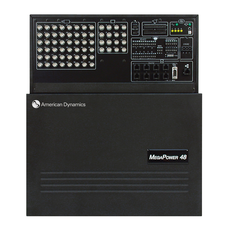
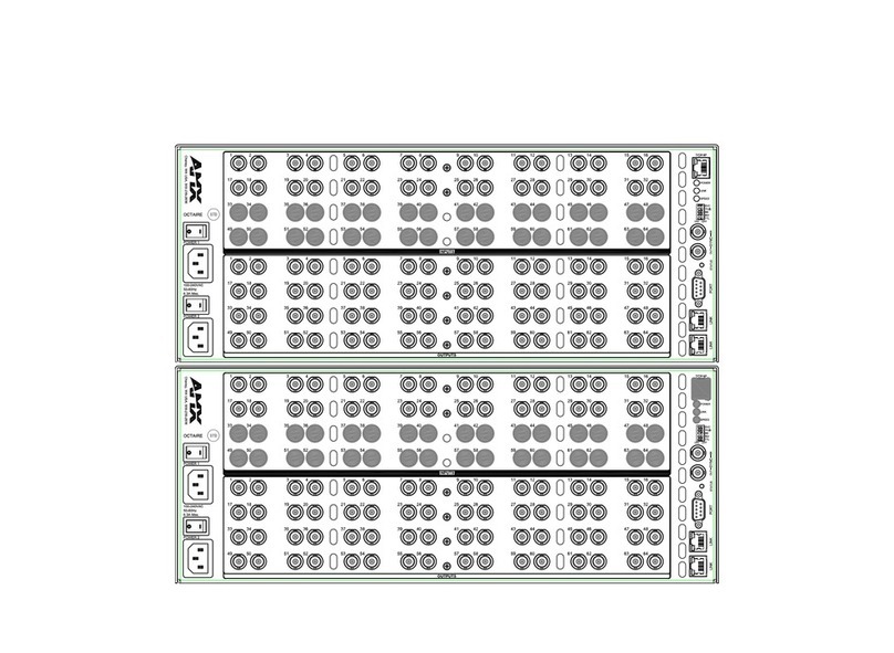
Modular, high-density, pre-packaged systems in any combination of 12 video input
and 6 video output increments (up to a maximum system configuration of 168 video
inputs by 24 video outputs).
RS-232 Communications
Eight ports allow standard communication with keyboards, alarm interface units,
computers, etc. Each port is individually programmable for data rates of 300, 1200,
2400, 4800, 9.6k, 19.2k, or 38.4k baud. Each port can expand to four ports with
optional port expander. This expands the available RS-232 ports to a maximum of 32.
Selectable On-Screen Text
Each monitor can display the date/time, video input number, user-definable video
input or Preset title (16 characters), alarm title (48 characters), and monitor status.
Three date formats are provided: MM/DD/YY, DD/MM/YY, or YY/MM/DD. The on-
screen text uses white characters with black outline to optimize viewing on diverse
contrast scenes. For increased visibility, all alarm titles appear on a colored
background. The user can turn the following displays on and off: the video input
number and monitor status, the video input/Preset title, and the date/time. Text
controls include incremental horizontal/vertical positioning and display brightness—
all adjustable via the keyboard.
Macro Control
The system’s powerful macros allow each operator to customize his or her own
AD2088 workstation to perform a multitude of tasks via simple, easy to remember
keystrokes that are intuitive to that operator. Once macros have been programmed for
a keyboard, that set of macros is stored locally.
Each keyboard can be programmed differently to accommodate individual user
preferences, needs and requirements. Alternatively, a set of macros can also be
“copied” from one keyboard to another. Macros allow for unsurpassed ease of use,
even with the most complex and demanding installations.
Recorder Control
Users can control all of the standard recorder functions directly from any suitably
equipped keyboard — play, stop, pause, record, rewind, fast forward and eject — for
both VCRs and digital recorders.
Pseudo Camera Numbers
For each video input, users can assign a 4-digit number to replace the default video
input number. This can aid operators in identification, such as in the case of multiple
level buildings.
Monitor Tours
A Tour is comprised of a sequence of up to 64 camera switches. An operator can
define a Tour for any video output at any time. The same video input may be inserted
multiple times in the same tour. Tours can be run forward or in reverse. Video inputs
partitioned from a monitor are automatically skipped.
System Tours
Sixty-four tours of video inputs or salvos may be established for callup to monitors at
any time. Each tour provides 64 positions for insertion of video inputs—each with an
individual dwell time, a Preset and an auxiliary action. Tours can be run forward or in
reverse. They can include the same video input multiple times and/or multiple Presets
and Patterns from a single camera. Tours can be connected together to form
Sequences of more than 64 video inputs. Video inputs partitioned from a monitor are
automatically skipped.
Event Timers
There are 35 user-programmable times available. These times may be independently
designated for multiple days of the week to automatically call up Universal Tours to
video output(s). Event timers also enable you to activate and deactivate alarm contacts
based on time of day.
Salvo Switching
Salvo switching allows multiple video inputs to be called simultaneously to multiple
contiguous video outputs. Sixty-four individual groups (Salvos), consisting of up to
16 video inputs (each with a Preset, Pattern and/or an auxiliary action), can be called
either manually or as part of a System Tour.
Automatic Alarm Callup—1024 Alarm Inputs
Alarm inputs can be programmed to call any video input or group of video inputs to
any one or more video outputs. A Preset or Pattern and/or auxiliary action, and
individual dwell time when sequencing alarms, may be defined for each alarm input.
Any combination of 25 alarm display/clearance methods may be selected
independently for each video output.
Alarm Contact Tables
The 1024 alarm contacts can be associated to any video input or Salvo (each with a
Preset and/or auxiliary action). Ten monitor/contact association tables are available
for inclusion in the 35 event timers to activate/deactivate alarm inputs.
Alarm Display Modes
The alarm display mode is user-selectable for each video output.
•Hold: Displays initial alarm until cleared. Queues subsequent alarms.
•Sequence: Sequences multiple alarms with individual dwell times until cleared.
•Sequence and Display: Displays initial alarm on one video output until alarm is
cleared. Subsequent alarms are sequenced on the next video output (while they are
active).
•Block Hold: Alarms are displayed on blocks (groups) of contiguous video outputs.
A block may consist of up to16 contiguous monitors. Multiple blocks can be
defined.
•Block Sequence: Alarms are sequenced on blocks (groups) of contiguous video
outputs. A block may consist of up to 16 contiguous monitors. Multiple blocks can
be defined.
Alarm Clearance Methods
The alarm clearance method is user-selectable for each video output.
•Manual: Removes an alarm only after the alarm has been manually acknowledged
by an operator.
•Clear: Automatically removes an alarm approximately 20 seconds after the alarm
input deactivates (if the alarm has not already been manually acknowledged). As a
security measure, manual acknowledgment may be disabled.
•Instant Clear: Automatically removes an alarm when an input deactivates (if the
alarm has not already been manually acknowledged). As a security measure, manual
acknowledgment may be disabled.
Status Output
System status output, parallel printer port, and RS-232 ports may be programmed to
output both occurrence of and clearance of all alarm and video loss events, as well as
power status and monitor messages. An alarm event message includes date/time of
event, contact number, video input number, and alarm status. A video loss message
includes date/time, video input number, sync loss, and detection mode.
System Partitioning
System flexibility is further enhanced by defining authorized access to keyboards,
video inputs, and video outputs. System partitioning includes the following:
•Keyboard-to-Monitor Access: Restricts selected keyboards from accessing selected
video outputs.
•Monitor-to-Camera Access: Restricts selected video outputs from displaying
selected video inputs.
•Keyboard-to-Camera Access: Restricts selected keyboards from calling or
controlling selected video inputs.
•Keyboard-to-Camera Control Access: Allows viewing of, but restricts selected
keyboards from controlling remote functions at selected camera sites.
Password and Priority Operation
Keyboards or users can be assigned one of eight levels of priority control of remote
camera sites. Up to 64 user codes, each with a unique password, can be assigned to
operators. Access to certain system features may be restricted depending on a user’s
priority level.
Internal Video Loss Detection
Video loss is standard on all video inputs. Upon video loss, this feature automatically
brings up a blue screen video and can be configured to alert the operator through on-
screen (program monitor) and/or printer messages.
Integral Color Bar Test Pattern
The pattern generator enables you to ensure that all of your monitors are set for
consistent display attributes such as brightness and contrast.
On-Board Diagnostics
The system's built-in diagnostics allow the user to determine the status of the
system's internal components via LEDs which can be easily seen through the clear
panel of the bay front panel.
Redundant Power Supply Port
In the unlikely event of the unit power supply failing, the system will automatically
switch to a user supplied DC power supply source.
