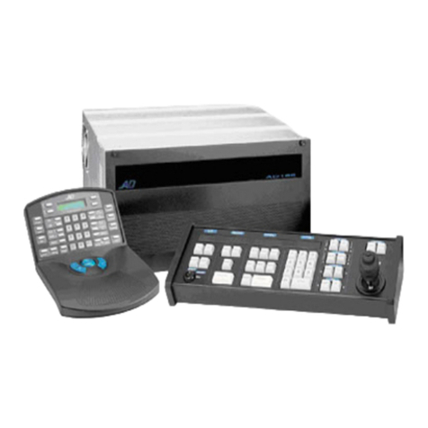
AD1024 CPU External Central Processing Unit
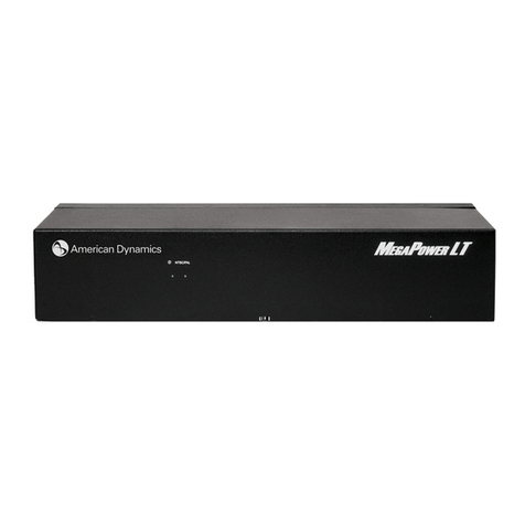
(CPU)
Included in every preconfigured AD1024 System Controls the entire switcher/
controller system. It includes 10 RS-232 data ports (expandable to 40), front panel
system diagnostic display, two High Speed Data Line outputs to switching bays and
accessories (each output supports 64 monitors). The CPU is compatible with the
AD1024HS Hot Switch.
AD1024CPU . . . . . . . . . . . . . . .AD1024 Matrix CPU, 120 VAC
AD1024CPU-1 . . . . . . . . . . . . . .AD1024 Matrix CPU, 230 VAC
AD2010R Switching Bays
High density video input modules (VIMs) and/or video output modules (VOMs) are
accommodated in a single bay. This bay provides for up to 256 video inputs and 16
video outputs without on-screen display, up to 192 video inputs and 16 video outputs
with on-screen display, or up to 64 video outputs only.
AD2010R . . . . . . . . . . . . . . . . . .Standard Matrix Bay, 120 VAC
AD2010R-1 . . . . . . . . . . . . . . . . .Standard Matrix Bay, 230 VAC
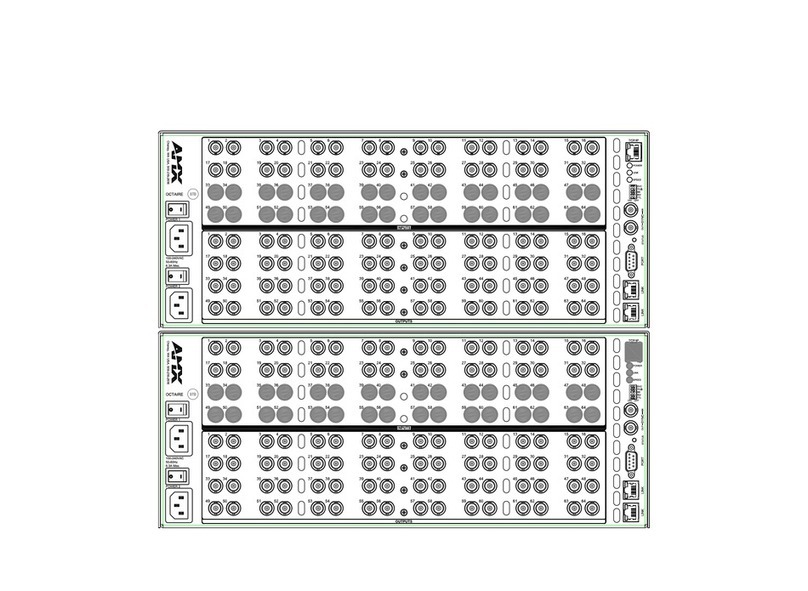
AD2020R Switching Bays
Up to 16 high density video input modules (VIMs) and/or video output modules
(VOMs) are accommodated in a single bay. This “bi-level” bay is used for condensed
system packaging. It provides up to 64 video inputs and 32 video outputs with on-
screen display, or up to 64 video outputs only.
AD2020R . . . . . . . . . . . . . . . . . .Bi-Level Matrix Bay, 120 VAC
AD2020R-1 . . . . . . . . . . . . . . . . .Bi-Level Matrix Bay, 230 VAC
AD2010PS Power Supply Module
Included in the AD2010 and AD2020 series switching bays. Front panel an on/off
switch and includes LED indicators to show status of the system’s vertical interval sync
signal (sync on/off and sync loss). The rear panel provides BNCs for High Speed Data
Line input/output, and external sync signal input/output.
AD2010PS . . . . . . . . . . . . . . . . .Power Supply Module for AD2010R, AD2020R Bays
AD2010PS-1 . . . . . . . . . . . . . . . .Power Supply Module for AD2010R-1, AD2020R-1 Bays
Note: 180° phase adjustable synchronization allows the installer to reference either the
AC line or external vertical sync pulse to facilitate roll-free vertical interval switching.
An on-screen setup mode enables the installer to match the power supply phase to the
camera phase.
AD2010DB Data Buffer Module
Included in the AD2010 and AD2020 series switching bays. Each module rear panel
supplies 16 video signals for connection to the AD2024VOM video output modules in
different bays.
AD2010DB . . . . . . . . . . . . . . . . .Data Receiver/Buffer Module
AD2010DBVL Video Loss Detection Module
In addition to providing the function of the standard AD2010DB Data Buffer Module,
this optional module also serves to detect video sync or signal loss. Each module can
detect video signals on a maximum of 256 video inputs. Transmission of video loss
activity is sent to the AD1024CPU series CPU via RS-232.
AD2010DBVL . . . . . . . . . . . . . .Video Loss Detection Module
AD2016AVIM Video Input Modules
The VIM card provides switching for a maximum of 16 video inputs to a maximum of
16 video outputs.
AD2016AVIM-1 . . . . . . . . . . . . .Input Module, Single Level
AD2016AVIM-2 . . . . . . . . . . . . .Input Module, Level 1 of Multi Level System
AD2016AVIM-3 . . . . . . . . . . . . .Input Module, Level 2 of Multi Level System
AD2016AVIM-4 . . . . . . . . . . . . .Input Model for Looping/Additional Multi Level
Systems
AD2016PC . . . . . . . . . . . . . . . . .Input Card
AD2016BP-1 . . . . . . . . . . . . . . .VIM-1 Input Card Rear Panel
AD2016BP-2 . . . . . . . . . . . . . . .VIM-2 Input Card Rear Panel *
AD2016BP-3 . . . . . . . . . . . . . . .VIM-3 Input Card Rear Panel
AD2016BP-4 . . . . . . . . . . . . . . .VIM-4 Input Card Rear Panel*
* Includes AD2016CB 30” (76 cm) cables.
AD2024AVOM Video Output Modules
The VOM card provides four video outputs per module. Each output provides
on-screen text generation and control text positioning.
AD2024AVOM-1 . . . . . . . . . . . .Output Module, w/Single Width Rear Panel
AD2024AVOM-2 . . . . . . . . . . . .Output Module, w/Double Width Rear Panel
AD2024PC . . . . . . . . . . . . . . . . .Output Card
AD2024BP-1 . . . . . . . . . . . . . . .VOM-1 Output Card Rear Panel
AD2024BP-2 . . . . . . . . . . . . . . .VOM-2 Output Card Rear Panel
ADULP Universal Loop Panels
The optional panels facilitate looping video signals to other video equipment.
ADULP . . . . . . . . . . . . . . . . . . . .Looping Panel
ADULP-30 . . . . . . . . . . . . . . . . .Looping Panel, w/Two AD2016CB 30" (76 cm) Cables
ADULP-96 . . . . . . . . . . . . . . . . .Looping Panel, w/Two AD2016CB8 96" (244 cm) Cables
AD2024MDT Master Date Time Module
This optional module is intended for dedicated video inputs to dedicated video
outputs. Synchronized system time and date information can be inserted on each of
the four video outputs.
AD2024MDT . . . . . . . . . . . . . . .Date/Time Module
MP1000cc, AD2088, AD2088R, AD2088-1,
AD2088R-1, ADTTE
Full system keyboards allow for video switching, pan/tilt control, dome control, auxiliary
control, macro and recorder control (MP1000cc and AD2088 only), and system
programming. The keyboards support bi-directional communication with the
AD1024CPU via RS-232 ASCII commands.
AD1981, AD1981X Port Expander
Expands one RS-232 port on a system into four ports. This provides connections to
multiple system keyboards.
AD2091, AD2091-1 Manchester Code
Generator/Distributor
Interfaces with the matrix switcher/controller system via High Speed Data Line and
provides 64 AD Manchester code outputs for use by receiver/drivers and suitably-
equipped pan/tilts and domes. Multiple units can be cascaded together.
AD2083-02B, AD2083-02B-1 SEC RS-422
Code Generator/Distributor
Interfaces with the matrix switcher/controller system via High Speed Data Line and
provides 16 SEC RS-422 outputs for use by suitably-equipped domes. Multiple units can
be cascaded together.
AD2096A, AD2096-1 Alarm Interface
Supervises up to 64 alarm inputs and provides RS-232 ASCII alarm commands to the
system. Alarm inputs can be programmed to call any video input, display any preset, or to
initiate any auxiliary action. Up to 16 units can be cascaded on a single RS-232 line.
AD1024HS, AD1024HSX CPU Hot Switch
Provides backup protection to insure uninterrupted system operation. Continuously
monitors the data lines of two separate CPUs for normal operation. When the
AD1024HS detects a CPU malfunction, it automatically selects the alternate CPU to
provide uninterrupted system operation.
AD2031, AD2031-1 Switcher Follower
Activates relays when designated video inputs are called to designated video outputs. It
interfaces with the matrix switcher/controller system and provides up to 32 Form A
relays, via High Speed Data Line, that can be grouped in series and addressed to a single
video output, or in two groups of 16 relays for two specific video outputs. Multiple units
can be cascaded together.
AD2032, AD2032-1 Alarm Responder
Activates relays when associated video outputs are in their alarming condition. Interfaces
with matrix switcher/controllers and provides up to 32 Form A relays via High Speed
Data Line. Multiple units can be cascaded together.
AD2033, AD2033-1 Auxiliary Follower
Activates relays when a specific auxiliary is triggered (either manually or automatically)
for an associated video input. Interfaces with matrix switcher/controllers and provides up
to 32 Form A relays via High Speed Data Line. Multiple units can be cascaded together.
AD1983, AD1983X Code Converter
Converts Manchester code to two bytes of RS-232 control code for transmission on
standard RS-232 links. RS-232 receiver/drivers may be connected directly to the link (a
separate RS-232 distributor may be required), or a receiving AD1983 Code Converter may
be used to convert the signal back to Manchester code for use by standard
receiver/drivers.
AD1024CG Four-Channel Character Generator
Displays same title, time/date information as AD2024VOM or can operate as a
standalone unit. Interfaces with AD1024 System via High Speed Data Line. Multiple
units can be cascaded together.
Recorder Control Devices
The series of recorder control devices allow for remote control of VCRs and digital
recorders via the AD2088 Full System Keyboard. This enables users to have integrated
control of the most popular types of recorders.
•The AD100XA/AD100XA-1A Recorder Controller is the CPU of the recorder
interface network. Just one recorder controller can accommodate the entire network,
and it enables the programming of the various recorder control devices.
•The AD100IR16/AD100IR16-1A IR Interface Module controls any recorder that has
IR capability and is supplied with an IR remote (used to learn the IR commands).
•The AD100RL8/AD100RL8-1 Resistive Ladder Module controls recorders that can
be controlled via resistive ladder.
•The AD100RS8/AD100RS8-1 RS-232 Module controls RS-232 VCRs and digital
recorders.

