American Legend AL1200W User manual

1-888-996-2729
FAX: 1-866-873-3531
We strive to ensure that our products are of the highest quality
and free of manufacturing defects or missing parts. However, if
you have any problems with your new product,
DO NOT RETURN IT TO THE STORE ,
please contact us toll free @:
Your Model Number ____________________
have your model number when inquiring about parts.
Please
Date Code ___________________________
2 - AL1200F- - SY
When contacting Escalade Sports please provide your model number, date
code (if applicable) and part number if requesting a replacement part. These
numbers are located on the product, packaging, and this owners manual.
Purchase Date ________________________
PLEASE RETAIN THIS INSTRUCTION MANUAL FOR FUTURE REFERENCE
AL1200W/F
Mailing Address: (Correspondence Only)
Escalade Sports
PO Box 889
Evansville, Indiana 47706-0889
Physical Location:
Escalade Sports
817 Maxwell Ave.
Evansville, Indiana 47711
For Customer Service Call 1-888-996-2729
V.1
© 2023 Escalade S por t s
All Rights Reserved
1

72 INCH X - LEG LED AIR HOCKEY TABLE
IMPORTANT! READ EACH STEP
IN THIS MANUAL BEFORE YOU
BEGIN THE ASSEMBLY.
Tools Required:
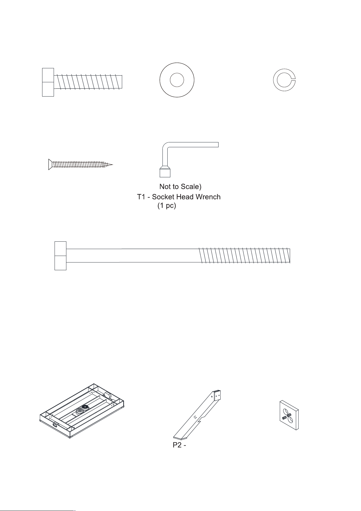
Socket Head Wrench (Included)
Furniture Polish and Cloth
Carpenters Level
Phillips Screw Driver
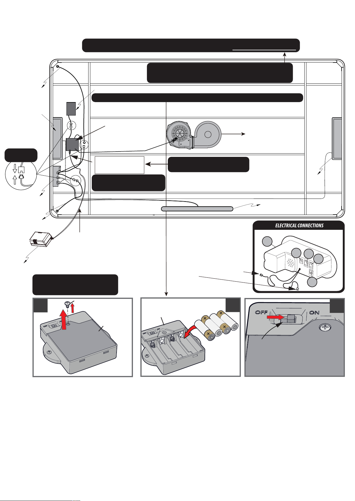
(AA Batteries are for store display use only)( A/C Adapter is for residential use only)
(4 pcs AAA Batteries for strikers-Not included)
4 pcs AA Batteries (Not Included), A/C Adapter (Included)
For Customer Service Call 1-888-996-2729
© 2023 Escalade S por t s
All Rights Reserved
2
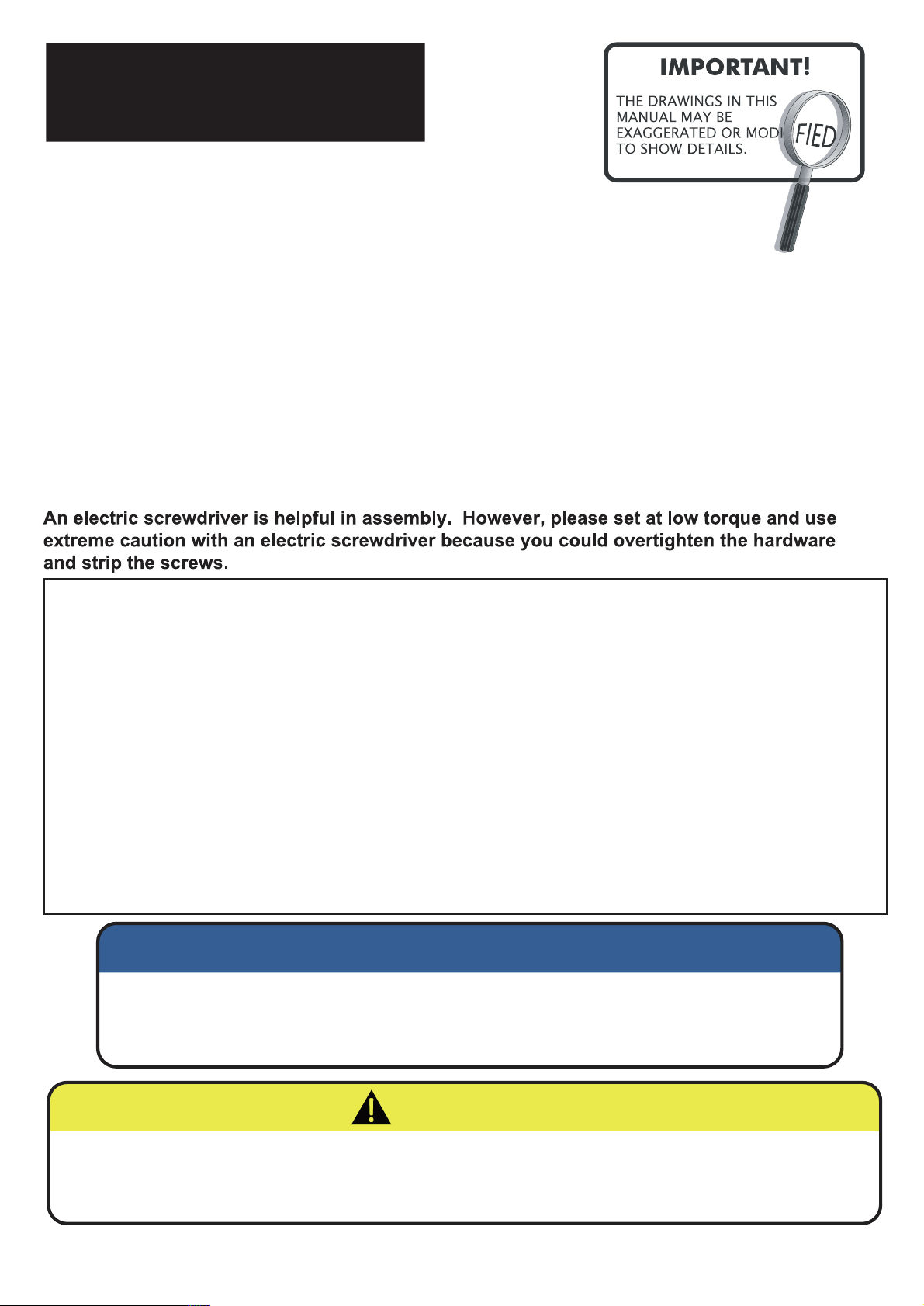
Make sure you understand the following tips before you begin to assemble your game table.
1. Start all bolts by hand before tightening.
2. Some drawings or images in this manual may not look exactly like your product. Please
read and understand the text before starting each assembly step.
Assembly Tips
3. Assembly can be made both simpler and less timely by first unpacking all parts , and
matching and organizing them to the Parts Identifier . This will greatly help you become
familiar with the parts before and during assembly .
4. Some of this assembly can be made easier – by placing the parts and building the assembly
on a pair of saw horses . A table can be used also as long as the top is well protected from
any scratches that could occur. The table or saw horses would need to be structurally strong
enough to support this weight.
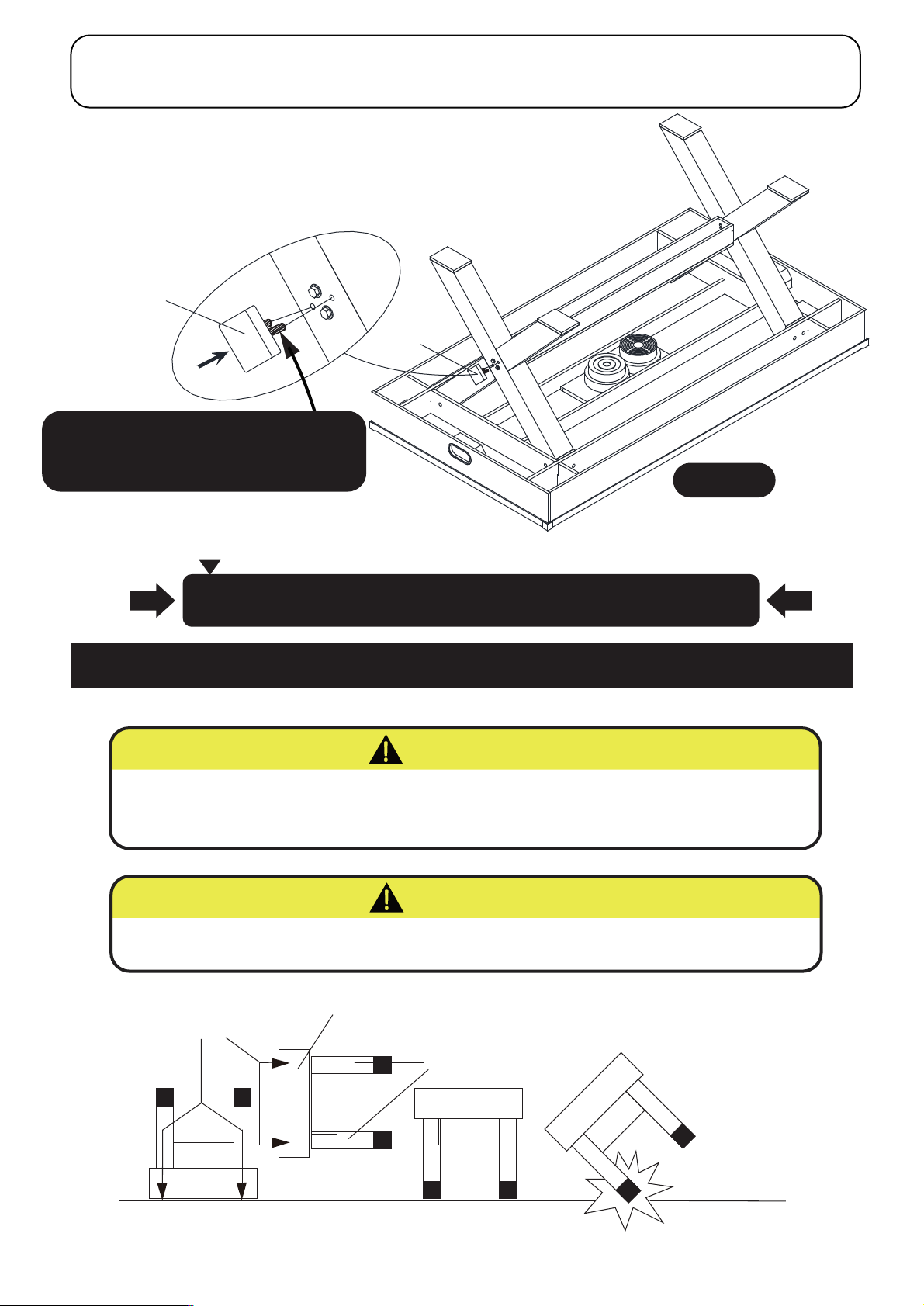
READ AND FOLLOW ALL ASSEMBLY, OPERATION, AND
SAFETY INSTRUCTIONS CAREFULLY. AT LEAST TWO CAPABLE
ADULTS ARE REQUIRED TO ASSEMBLE THIS GAME TABLE.
NOTICE :
AT LEAST FOUR OR MORE CAPABLE ADULTS ARE REQUIRED TO
LIFT AND ROTATE THIS GAME TABLE INTO PLAYING POSITION.
DO NOT LEAN THE TABLE ON ITS LEGS AS THIS COULD DAMAGE THEM.
CAUTION :

HARDWARE IDENTIFIER
(To Scale)
PARTS IDENTIFIER
(Not to Scale)
For Customer Service Call 1-888-996-2729
© 2023 Escalade S por t s
All Rights Reserved
3
(
H1 - 8mm x 40mm
Hex Head Bolt
(12 pcs)
H5 - 8mm x 130mm
Hex Head Bolt
(4pcs)
H2 - M8 Flat Washer
(16 pcs)
H3 - M8 Lock Washer
(16PCS)
H4 - 3.5 x 35mm
Phillips Flat Head Screw
(14 pcs)
Universal Leg
P1 - Main Cabinet
with Air Motor & Puck Catchers
(1pc)
(4pcs)
P3 -
Decorative Leg
Wooden Block
(2 pcs)

ACCESSORIES IDENTIFIER
(Not to Scale)
For Customer Service Call 1-888-996-2729
© 2023 Escalade S por t s
All Rights Reserved
4
P4 - Wooden End Block P5 - Top Panel of Lower
Center Support Beam P6 - Side Panel of Lower
Center Support Beam
A3
(1 pcs)(1 pc)(2 pcs) (2 pcs)
A4 - Felt Pad
A5 - A/C Adapter
A1 - LED Striker
4 pcs AAA batteries
will be required
(not included)
A2 - LED Puck
NOTE: A4 Felt Pads may already
be attached to A1 Strikers
Will assemble together
A6 - Table Leveling Shim
(4 pcs)

STEP 1
STEP 2
Attach the P4 End Blocks, onto the P5 Top Panel of
Lower Center Support Beam onto the P6
Side Panels of Lower Center Support Beam
using the H4 Phillips Flat Head Screws as
shown in FIGURE 1.
For Customer Service Call 1-888-996-2729
© 2023 Escalade S por t s
All Rights Reserved
5
PARTS REQUIRED
2pcs - P4 End Block 14pcs - H4 Phillips Flat Head Screw
1pc - P5 Top Panel of Lower Center Support Beam
2pcs - P6 Side Panel of Lower Center Support Beam
PARTS REQUIRED
(For Step 2 + Step 3)
4pcs - P2 Universal Leg
1pc - T1 Socket Head Wrench
4pcs - H
2
Flat Washer
4pcs - H
3
Lock Washer
4pcs - H
5
Hex Head Bolt
NOTE: Black laminate to outside.
P2 P2
FIGURE 2
FIGURE 1
Pilot Holes
P5
P4
P6
P4
P6
H4
H4
H4
H4
H4
Place together the four pcs of P2 Universal Legs
as
shown in FIGURE 2.
Be careful watch for pinch points.
Bolt holes
at bottom Bolt holes at bottom
NOTE: Keep edges flush.
NOTE: Each leg all have 4 holes
Do not strip out the H4 screws.
Heads of steel T-Nuts in parts P4
must be to the inside.
IMPORTANT

STEP 3
STEP 4
For Customer Service Call 1-888-996-2729
© 2023 Escalade S por t s
All Rights Reserved
6
PARTS REQUIRED
12pcs - H
1
Hex Head Bolt
12pcs - H
2
Flat Washer
12pcs - H
3
Lock Washer
FIGURE 3
H2
H3
H5
H5
H3
H2
H5
H3
H2
With the help from another adult, attach the Leg Support Beam
onto the “X” Legs using the H5 Hex Head Bolts, H2 Flat
Washers and H3 Lock Washers as shown in FIGURE 3.
Only hand tighten all leg bolts at this time.
H2
H1 H3 H2
H1 H3H2
H1
H3
H1 H3
H2
H2 H3H1
H2 H3H1
FIGURE 4
1pc - P1 Main Cabinet
With the help from another adult, lift the X Leg assembly onto the P1 Main Cabinet and attach
using the H1 Hex Head Bolts, H2 Flat Washers and H3
Lock Washers as shown in FIGURE 4.
Floor side
Extra single hole with not be used
Holes in bottom
of leg go down
Tighten all bolts tight in this step and from Step 3
using the T1 Socket Head Wrench.
IMPORTANT NOTE: When “ Starting” any bolts within this
table - use only minimal pressure as to not “ Push out” the inner “T” Nuts.
1pc - T1 Socket Head Wrench

STEP 5
For Customer Service Call 1-888-996-2729
© 2023 Escalade S por t s
All Rights Reserved
7
PARTS REQUIRED
FIGURE 5
P3
P3
Insert the P3
Decorative Leg Wooden Blocks
into
the "X" legs, as shown in Figure 5.
A light tap from a rubber hammer may be required.
2pcs - P3
Decorative Leg Wooden Block
NOTE: Before flipping the table - please check page 8 and locate
where the A5 A/C adapter will plug into the Junction Box.
NOTE for residential customers
IMPORTANT
NOTE: A small amount of wood glue
(not included) can be placed on the
dowel pins before assembly.
HOLD TABLE CABINET DO NOT
HOLD THE
LEGS
DO NOT LEAN THE
TABLE ON ITS LEGS!
VERY CAREFULLY TURN THE TABLE OVER AND SET IT ON
ITS LEGS. BE CAREFUL. THE TABLE IS VERY HEAVY.
LIFT + ROTATE THE TABLE
Always use proper lifting techniques
AT LEAST FOUR OR MORE CAPABLE ADULTS ARE REQUIRED TO
LIFT AND ROTATE THIS GAME TABLE INTO PLAYING POSITION.
DO NOT LEAN THE TABLE ON ITS LEGS AS THIS COULD DAMAGE THEM.
CAUTION :
CAUTION :

For Customer Service Call 1-888-996-2729
© 2023 Escalade S por t s
All Rights Reserved
8
NOTE: AA Batteries will only be used in store
displays. A/C Adapter used in residential use only.
NOTE: For store display
use only. (A+B+C)
(Store display use only)
NOTE: For store display use only (only powers LED Light Strip & Scorerboard.
NOTE: For residential
use only.
NOTE: Do not plug the A/C
adapter in when using batteries.
ELECTRONIC CONNECTIONS
C7. Scorer
C6. Air Motor
C3. Control Box
A5. A/C Adapter
Do not allow adapter cord
to become a trip hazard
A/C Adapter
plugs in here
Junction
Box
C4. Sensor with
Short Wire
C1. LED Rail with
Long Wire
C8. Battery box (
Require
4 pcs AAA batteries, not included)
NOTE: This product has two power supply methods: battery and A/C adapter.
C2. LED Rail with
Short Wire
C5.Sensor with
Long Wire
C3
A8
C7
C4
C5
To connect the C1/C2
AC
B
AA
AA
AA
AA
Battery Box
Note: Batteries
not included.
Screw
Cover
-Unscrew and remove cover. - Insert 4 AA Batteries
(Batteries not included).
Make sure polarity is correct.
- Return cover and reinsert screw.
See” FIRST TIME BATTERY INSTALLATION AND NOTICE “ , before installing batteries, located on page 13.
Remove the small screw using a small phillips screwdriver and open the battery box, Insert (4) AA
batteries (not included) in the order of correct polarity as shown on the inside of the battery box. Then
close using the same screwdriver. (If the game will not be used for a long period of the time, we recom-
mend that the batteries be removed)
LED ON/OFF and power ON/OFF
is on the scoreboard control.
Switch must remain in the
“ON” position
Factory
connected

For Customer Service Call 1-888-996-2729
© 2023 Escalade S por t s
All Rights Reserved
9
Valued Customers:
This product will be powered in your homes with the A/C adapter only.
The battery pack will not be used or needed in your home environment.
lt is simply not needed.
IMPORTANT NOTE TO OUR VALUED RETAIL
CUSTOMERS AND STORE MANAGERS
Thanks all for your understanding.
DO NOT USE THE BATTERY PACK !
Store Manager:
For display reasons, a battery pack and directions for use are included with this
product and in the assembly manual. Please note that the battery pack will only power the
LED playfield lights and electronic scoring. The air fan motor will not be powered by the
sole battery pack.
Do not plug the A/C adapter into the Junction Box when using batteries.

For Customer Service Call 1-888-996-2729
© 2023 Escalade S por t s
All Rights Reserved
10
STEP ONE :
Should the LED lights not be working in the rail - Firstly , make sure the A/C Adapter is plugged in to a live A/C
outlet properly. Secondly , make sure the A/C Adapter
(A5)
is tightly plugged into Junction Box outlet under the table .
Lastly, make sure all LED Rail light connections are snuggly plugged into the Control Box
(C3)
. At this point, if the
LED Rail Lights still not be working , please disconnect the A/C power to the table before proceeding .
A call will be required to our Customer Service Department to acquire the necessary replacement part(s).
Replacement of LED Light Strip(s)
C1/C2
C9
STEP THREE:
Install the replacement LED Strip C1 & C2 back to the Cabinet Side Rail. Align the male and female connectors
of the Lighting LED Strip. Connect the plug of C1 & C2 Lighting LED Strip with C3 Control Box Wire.
C1
C1 & C2
C3
C2
C1 & C2
C9
DETAIL A
STEP TWO :
If the LED Light Strip needs to be replaced on the P1 Cabinet inner side, carefully pry the C9 LED Strip Cover
out of the apron with the help of a flat blade screwdriver as shown in DETAIL A, then remove the C1 & C2 LED
Light Strip from the table.
The LED Light Wire Connection will need to be disconnected first , the connection is under the table , please
see page 8 .

For Customer Service Call 1-888-996-2729
© 2023 Escalade S por t s
All Rights Reserved
11
SCOREBOARD CONTROL PANEL OPERATION
LED RAIL LIGHT
POWER ON/OFF
SCORERBOARD
& AIR MOTOR ON / OFF
TIME OUT
PLAYING TIME
VOLUME UP
PAUSE PLAY
SCOREBOARD CONTROL PANEL OPERATION
SCOREBOARD POWER
LED RAIL LIGHT POWER
scoreboard and air motor ON
rail light ON
PLAYING TIME
VOLUME DOWN
This Control Box does have an automatic turn off feature after twenty minutes of inactivity
(Air motors and all electronics).

For Customer Service Call 1-888-996-2729
© 2023 Escalade S por t s
All Rights Reserved
12
LED PUCK BATTERY CHANGE INSTRUCTION
STEP ONE:
(Includes the Lithium Battery)
Remove screws and back
cap from LED Puck using Small
Phillips Screwdriver (not provided).
STEP TWO:
Remove CR2016 Lithium
Battery 3V from LED Puck.
STEP THREE:
Insert new CR2016 Lithium Battery 3V
into LED Puck.
STEP FOUR:
Install back cap and secure screws with Phillps Screwdriver
(not provided).
Positive “+”
on bottom
side
LED STRIKER BATTERY INSTALLATION/REPLACE INSTRUCTION
NOTE:
Make sure the on/off
switch on the back
cap properly aligns
and fits into its slot in
the LED puck during
reassembly
IF BATTERY HOLDER BRACKET
MOVES, RE-INSTALL IT TO LED
PUCK AS SHOWN IN DIAGRAM.
Helpful Hint:
The LED puck battery will last approximately 7 hours of continuous play. The puck battery is not
rechargeable. Be sure to turn the switch to the “OFF” position when not in use to conserve your
battery life.
Helpful Hint:
Be sure to turn the switch to the “OFF” position when not in use.
AAA
AAA
(Batteries not included).
Make sure polarity is correct.
See” FIRST TIME BATTERY INSTALLATION AND NOTICE “ , before installing batteries, located on page 13.
Top cap
Carefully twist
top cap off to
replace batteries
Carefully replace
top cap when the
batteries are replaced.
Do not cross thread
ON/OFF Switch
(Does not Include the 4 pcs AAA Batteries)

For Customer Service Call 1-888-996-2729
© 2023 Escalade S por t s
All Rights Reserved
13
First Time Battery Installation:
Locate battery compartment for this product .
Use alkaline batteries for maximum performance .
Remove battery compartment cover .
Install new batteries only after reading the “ Battery Information NOTICE“ !
Replace compartment cover and secure cover.
Notice:
1. Remove and replace batteries when the electrical features of this product work slowly or are not
functional .
2. Do not mix old and new batteries .
3. Do not mix different types of batteries : Alkaline , Standard ( Carbon-Zinc) , or rechargeable
( Nickel-Cadmium batteries ) .
4. Use Alkaline Batteries for maximum performance .
5. Do not use damaged batteries .
6. Use only batteries of the same or equivalent type as recommended.
7. Install new batteries as per matching the battery polarity guide ( + & - , positive and negative ) inside
of the battery compartment . Correct battery polarity installation is critical as to not damage the internal
electrical components as well as insuring the correct functionality of the product .
8. Do not short circuit the battery terminals .
9. Always remove exhausted , leaking, weak , and batteries from long periods of nonuse from the
product . Battery leakage and corrosion can cause damage .
10. Check the battery terminals are clean and bright before installing new batteries.
11. Dispose of old batteries safely and per local battery disposal codes .
12. Do not dispose of batteries into a fire as they may explode or leak.
13. If removable rechargeable batteries are used , they are to be charged under adult supervision .
14. Rechargeable batteries are to removed from the product before they are charged .
15. If you use a battery charger, it should be examined regularly for damage to the cord , plug, enclosure,
and other parts. Do not use a damaged or malfunctioning charger until it is properly repaired.
16. Non rechargeable batteries must not be recharged .
17. Always remove batteries from this product for extended storage and or non-use .
18. Should this product cause , or be affected by, local electrical interference , move it away from other
electrical equipment . Reset ( switching off and back on again and or removing and reinserting the
batteries ) if necessary .
IMPORTANT: BATTERY INFORMATION
Please retain this information for future reference. Batteries must be installed / replaced by an adult .
NOTE: For store display use only.

Congra tula tion s! Y ou ha v e now a ssembled your game table. Plea s e no t e the Car e
and Use instructions below to insure many years of trouble free use of your game
t a b l e.
Description Qty.
H1
H2
H3
H4
T1
P1
P2
P3
P4
P5
Key # Part #
PRODUCT PARTS LIST FOR MODEL # AL1200W/F
AL1200SYH1
AL1200SYH2
AL1200SYH3
AL1200SYH4
AL1200SYT1
AL1200SYP1
AL1200SYP2
AL1200SYP3
AL1200SYP4
AL1200SYP5
8mm x 40mm Hex Head Bolt
M8 Flat Washer
M8 Lock Washer
3.5mm x 35mm Phillips Flat Head Screw
8mm x 130mm Hex Head Bolt
Main Cabinet with Air Motor & Puck Catchers
Universal Leg
Wooden End Block
Top Panel of Lower Center Support Beam
12
16
16
14
H5 AL1200SYH5 3.5mm x 35mm Phillips Flat Head Screw 14
4
1
4
2
2
1
P6 AL1200SYP6 Side Panel of Lower Center Support Beam 2
Decorative Leg Wooden Block
A1
A2
A3
AL1200SYA1
AL1200SYA2
AL1200SYA3
LED Striker
LED Puck
Puck
K1
M1 AL1200SYK1
AL1200SYM1
Hardware Kit
Owner's Manual
2
1
1
A4 AL1200SYA4 Felt Pad 2
A5 AL1200SYA5 A/C Adapter 1
A6 AL1200SYA6 Table Leveling Shim 4
A7 AL1200SYA7 Metal Corner Cap(pre-installed) 4
C1
C2
C3
AL1200SYC1
AL1200SYC2
AL1200SYC3
LED Rail With Long Wire
LED Rail With Short Wire
Control Box
1
1
1
C4 AL1200SYC4 Sensor With Long Wire 1
C5 AL1200SYC5 Sensor With Short Wire 1
C6 AL1200SYC6 Air Motor 1
C7 AL1200SYC7 Scorer 1
C8 AL1200SYC8 Battery Box 1
C9 AL1200SYC9 LED Rail Cover 2
1
1
CA R E AND U SE OF YO UR T A B L E
1 . Use spray furniture polish to clean all exterior surfaces of your table.
3. This product is intended for INDO O R u s e onl y .
4 . D O N O T sit, climb or lean on the table.
5 . D O N O T drag the table when moving it. This will damage the legs .
6 . D O N O T set drinks on the table.
7 . The purchase of a table cover will both protect and help keep clean the
8.
Use a carpenters level to properly level the table using the enclosed A6 leveling shims.
entire top of the table.
2 . Use spray funiture polish on the AH playing surface with motor running. This will
protect the playing surface + make the pucks go faster.
For Customer Service Call 1-888-996-2729
© 2023 Escalade S por t s
All Rights Reserved
14

For Customer Service Call 1-888-996-2729
© 2023 Escalade S por t s
All Rights Reserved
15
INSTRUCTIONS FOR LEVELING A GAME TABLE
Assemble game table according to the instruction.
Any type of level would be sufficient to perform this procedure. However, a two-foot level is
recommended.
Before leveling, make sure level is placed on the playing surface if possible, not the rails.
Level the ends: Place the level on the playing surface and adjust the height by placing
shims (A6) underneath the leg opposite of which the bubble in the level favors until
the bubble rests in the middle of the level.
Repeat the step above to the opposite end of the game table.
Next, level the length of the table. Place the level next to the side of the table and adjust the
height to position the bubble in the middle of the level, using the shims
opposite of which the bubble in the level favors.
Repeat the step above to the opposite length of the table.
Recheck both short ends to ensure bubble is in the middle on the level.
Depending on the surface the game table sits, especially deep pile carpenting, the game table
needs to settle for 24 hours. Recheck the level on each side of the table after 24 hours.
UN-LEVEL UN -LEVEL LEVEL
Add Sh im Add Sh im

For Customer Service Call 1-888-996-2729
© 2023 Escalade S por t s
All Rights Reserved
16
This consumer warranty extends to the original consumer purchase of any ESCALADE SPORTS
Product (hereinafter referred as the "Product").
WARRANTY DURATION: This Product is warranted to the original consumer purchase of a pe-
riod of 90 days from the original purchase.
WARRANTY COVERAGE: ESCALADE SPORTS warrants to the original Consumer Purchaser
that any Product of its manufacture is free from defects in material and workmanship when used
for the intended purpose under normal use and conditions. THIS WARRANTY IS VOID IF THE
PRODUCT HAS BEEN DAMAGED BY ACCIDENT, UNREASONABLE USE, NEGLIGENCE,
IMPROPER SERVICE, FAILURE TO FOLLOW INSTRUCTIONS PROVIDED WITH THE PROD-
UCT OR OTHER CAUSES NOT ARISING OUT OF DEFECTS IN MATERIAL AND WORKMAN-
SHIP.
WARRANTY PERFORMANCE: During the above 90 day warranty period, ESCALADE SPORTS
shall repair or replace with a comparable model, and Product, or component thereof, which may
prove defective under normal use and proper care, and which our examination shall disclose to
our satisfaction to be thus defective, please contact our Warranty Dept.
1-888-996-2729 / Warranty Dept.
Or Write us at:
Escalade® Sports, Inc. - P.O. Box 889, Evansville, IN 47706
Attn: Warranty Dept.
Or E-mail us at:
Other than shipping requirements no charge will be made for such repair or replacement of in-
warranty Products. ESCALADE SPORTS strongly recommends that the Product is insured for
value prior to mailing.
WARRANTY DISCLAIMERS: ANY IMPLIED WARRANTIES ARISING OUT OF
THIS SALE, INCLUDING BUT NOT LIMITED TO THE IMPLIED WARRANTIES OF
MERCHANTABILITY AND FITNESS FOR A PARTICULAR PURPOSE, ARE LIM-
ITED IN DURATION TO THE ABOVE 90 DAY PERIOD. ESCALADE SPORTS
SHALL NOT BE LIABLE FOR LOSS OF USE OF THE PRODUCT OR OTHER
CONSEQUENTIAL OR INCIDENTAL COSTS, EXPENSES OR DAMAGES IN-
CURRED BY THE CONSUMER OF ANY OTHER USE.
Some states do not allow the exclusion or limitation of implied warranties or consequential or
incidental damages, so the above limitations or exclusions may not apply to you.
LEGAL REMEDIES: This warranty gives you specific legal rights and you may also have other
rights which may vary from state to state.
90 DAY LIMITED WARRANTY
NOT COVERED BY THIS WARRANTY
• Product not intended to be in places of public assembly, such as, but not limited to, schools, parks,
public or private recreational facilities
• Any product subjected to Non-residential abuse, negligence, improper installation, vandalism, acts
of God, alteration of product, or any other events beyond the control of ESCALADE SPORTS.
This manual suits for next models
1
Table of contents
Other American Legend Indoor Furnishing manuals
Popular Indoor Furnishing manuals by other brands

Lancaster
Lancaster 30195 Assembly instruction

Fackelmann
Fackelmann 87218 Instructions for mounting and use

Choice Cabinet
Choice Cabinet Premier instructions

Whalen
Whalen Sagemoor SAGE7PD-E Assembly instructions

AmazonBasics
AmazonBasics B01D7P5BFS manual

fantastic furniture
fantastic furniture Nicholls Coffee Table Square Black Ash manual

fantastic furniture
fantastic furniture TORONTO Assembly instructions

Exclusive Heritage
Exclusive Heritage CL-10160D-WMTP installation guide

KLOBER
KLOBER Connex2 operating instructions

Coaster
Coaster 183645 Assembly instructions

VECELO
VECELO KHD-XJM-TC07A Assembly instruction

Ameriwood HOME
Ameriwood HOME 5317340EBL manual