American Legend HT600F220 User manual

&neabsn#egrendr
We strive to ensure that our products are of the highest quality
and free of manufacturing defects or missing parts. However, if
you have any problems with your new product,
DO NOT RHTURN IT TO THE STORE,
please contact us toll free @:
1-B88 -996-2729
1-866-873-353 I
X:
FA
All Rights Reserved
O 2014 Escalade Sports
gamero o m@e s c alade sp orts . c om
Or write to:
Escalade Sports
Customer Service Department
P.O. Box 8Bg
Evansville,lN 47206
Please visit our Web site at:
-''
r,luvw. e s c (| | o d e s po rt s."o \u
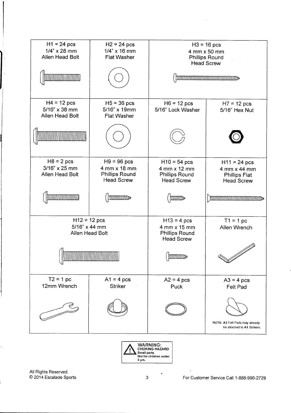
Please have your date code when inquiring about parts.
When contacting Escalade Sports please provide your model number, date code (if
applicable), and part number if requesting a replacement part. These numbers are
located on the product, packaging, and in this owners manual.
Your Modet Number_ HT600 F22A
DateCode: 2-HT600F22A
Purchase Date.
PLEASE RETAIN THIS INSTRUCTION MANUAL FOR FUTURE REFERENCE
1" For Customer Service Call 1-988-996-2729

IMPORTANT! READ EACH STEP
IN THIS MANUAL BEFORE YOU
BEGIN THE ASSEMBLY.
TWO ADULTS ARE REQUIRED TOASSEMBLE
THIS HT6OOF22OPHAZER 7.5 FT AIR HOCKEY TAl
Tools Required:
T1 - Allen Wrench (lncluded) andT2 - Wrench (lncluded)
Phillips Screwdriver
Furniture Polish and Cloth
An electric screwdriver is helpful in assembly. However, please set at low torque and usr
extreme caution with an electric screwdriver because you could overtighten the hardwarr
and strip the screws.
Assembly Tips
Make sure you understand the following tips before you begin to assemble your hockey t
1. Start all bolts by hand before tightening.
2. Some drawings or images in this manual may not look exactly like your product. Plee
read and understand the text before starting each assembly step.
&,wf,n!{rruG:
READ AND FOLLOW ALL ASSEMBLY OPERATION, AND
SAFETY INSTRUCTIONS CAREFULLY. AT LEAST TWO
ADULTS ARE NEEDED TO PUT THIS HOCKEY TABLE
TOGETHER.
All Rights Reserved.
A zOM Escalade Sports
THE DRAWINCS IN THIS
MANUAL MAY BE
EXACGERATED OR MOD
TO SHOW DETAILS.
For Customer Service Call 1-8t

H1 = 24 pcs
114" x 28 mm
Allen Head Bolt
H2 = 24 pcs
114" x 16 mm
Flat Washer
H3 = 16 pcs
4mmx50mm
Phillips Round
Head Screw
H4 = 12 pcs
5116" x 38 mm
Allen Head Bolt
H5 = 36 pcs
5116" x 19mm
Flat Washer
H6 = 12 pcs
5/16" Lock Washer
A\
Uu
\\-,
v
H7 = 12 pcs
5/16" Hex Nut
@
H8=2pcs
3/16" x 25 mm
Allen Head Bolt
H9 = 96 pcs
4mmx18mm
Phillips Round
Head Screw
H10 = 54 pcs
4mmx12mm
Phillips Round
Head Screw
(Nr
u'
H11 = 24 pcs
4mmx44mm
Phillips Flat
Head Screw
H12 = 12 pcs
5116" x 44 mm
Allen Head Bolt
H13 = 4 pcs
4mmx15mm
Phillips Round
Head Screw
T1 =1pc
Allen Wrench
T2=1pc
12mm Wrench A1 =4pcs
Striker A2=4pcs
Puck A3=4pcs
Felt Pad
t\
\T\
t\\l
\v
NOTE: A3 Felt Pads may already
be attached to 41 Strikers
WARillFlG;
CHOKING HAZARD
Small parts.
Not for children undet
3 yrs.
All Rights Reserved.
A 20114 Escalade Sports For Customer Service Call '1-888-996-2729

P1 =1pc
Air Hockey Cabinet P2=4pcs
Left Leg Panel P3=4pcs
Right Leg Panel P4=4pcs
Front Leg Par
P5=4pcs
Back Leg Panel P6=4pcs
Leg Bottom Board P7 =2pcs
End Leg Panel
NOTE: P7 End Leg Panels are
packed under the table €binet.
P8=2pcs
End Apron
H
ll h '\J.
P9=1pc
Side Apron P10=1pc
Side Apron with
ON/OFF slot
P11 = 12 pcs
U - Plastic Bracket P12 = 12 pcs
L - Plastic Brac
-re\
w
P13 = 4 pcs
Corner Post P14 = 8 pcs
Leg Panel
Connecting Plate
P15 = 4 pcs
Leg Leveler P16 = 2 pcs
Puck Catche
Hole Trim
n)
v
WARNING:
CHOKING HAZARD
Small parts.
Not for children under
3 y6.
All Rights Reserved.
@ 2014 Escalade Sports For Customer Service Call 1-888-91

I
I
IP17=1pc
Scorer Console P18 = 2 pcs
Lower Puck Catcher
with Sensor \Mres
P19=1pc
A/C Adapter P2O=1pc
ON/OFF Switch
P21=1pc
Metal Bracket P22= 2 pcs
Upper Puck Catcher P23=1pc
Junction Box
(Factory lnstalled)
P24 = 2 pcs
Lighting LED Rail
(Factory Installed)
WARNING:
CHOKING HAZARD
Small parts.
Not for children under
3 y6.
All Rights Reserved.
A 2014 Escalade Sports For Customer Service Call 1-888-996-2729

PARTS REQUIRED:
48 pcs - H9 Phillips Round Head Screw 1
2 pcs - P8 End Apron
1 pc - P9 SideApron
pc - P10 SideApron with
ON/OFF Slot
12 pcs - P11 U-Plastic Bracket
STEP 1:
Leave Pl Air Hockey Table cabinet face down in carton to assemble.
lnstall four pieces Pl1 U-Plastic Bracket onto two pieces P8 End Apron, one piece p9 Side Apro
one piece P10 SideApron with ON/OFF Slot using U-Guides with four pieces H9 Screws as shor
FIGURE l and DETAILA.
IMPORTANT NorE: TIGHTEN, BUT Do Nor srRtp our H9 scREWs.
All Righls Reserved
O 2014 Escalade Sports
,;
For Customer Service Call 1-888-99

i\ PARTS REQUIRED:
12 pcs - H4Allen Head Bolt 1 pc - Pl Air Hockey Table Cabinet
24 pcs - H5 Flat Washer 1 pc - T1 Allen Wrench
12 pcs - H6 Lock Washer 1 pc - T212mm Wrench
12 pcs - H7 Hex Nut
STEP 2:
Leave P1 Air Hockey Table Cabinet face down in carton to assemble.
lnstall P8 End Aprons and P9 lP10 SideAprons from assembly STEP 1 using H4Allen Head Bolts,
H5 Flat Washers, H6 Lock Nuts and H7 Hex Nuts as shown in FIGURE 2 and DETAIL B.
IMPORTANT NOTE: DO NOT TIGHTEN H4 BOLTS ON THIS STEP.
IMPORTANT NOTE: P10 SIDE APRON WITH ON/OFF SLOT MUST CLOSE TO P23 JUNCTION
BOX AS SHOWN IN FIGURE 2.
All Rights Reserved
O 2014 Escalade Soorts
I
tc
n
For Customer Service Call 1-888-996-2729

PARTS REQUIRED:
4 pcs - P13 Corner Post
STEP 3:
Slide Pl3 Corner Posts to each end of Side Apron and End Apron as shown in FIGURE 3.
TMPORTANT NOTE: SLIDE Pl3 CORNER POSTS WITH ARROW POINTING DOWN.
TIGHTEN ALL H4 BOLTS ON THIS TIME.
All Rights Reserved
O 2014 Escalade Sports
NOTE: lnstall P13 Corner
with arrow pointing down.
For Customer Service Call 1-88

PARTS REQUIRED:
48 pcs - H9 Phillips Round Head Screw
12 pcs - P12 L-Plastic Bracket
STEP 4:
With the help of another adult, Install P12 L-Plastic Brackets onto Pl Air Hockey Table Cabinet,
P8 End Aprons and P9 / P10 Side Aprons using H9 Phillips Round Head Screws as shown in
FfGURE 4 and DETAIL C.
IMPORTANT NOTE: TIGHTEN, BUT DO NOT STRIP OUT H9 SCREWS.
?9
li
I !,
@
{di '
H9
A
lt
li
All Rights Reserved
O 2014 Escalade Soorts For Customer Service Call 1 -888-996-2729

18 pcs - H10 PhilliPs Round Head
4 pcs - H13 PhilliPs Round Head
REQUIRED:
2 pcs - P{6 Puck Catcher Hole Trim
2 pcs - P18 Lower Puck Catcher with Sensor Wl
2 pcs - P22 UPPer Puck Catcher
PARTS
Screw
Screw
STEP 5:
secure P13 Corner Posts using H10 Screws as shown in FIGURE 5'
E Install pl6 puck Catcher Hole Trims using pre-drilled holes with Hl3 Screws as shown in FIGU
H tnstalt p22 Upper puck Catchers using pre-drilled holes with Hl0 Screws as shown in FIGURE
E tnstatt plg Lower puck Catchers with Sensor Wres using pre-drilled holes with Hl0 Screws as
shown in FIGURE 5.
IMPORTANT NOTE: TIGHTEN, BUT DO NOT STRIP OUT H1O AND H13 SCREWS.
Next, feed the sensor plugs from Pl8 through underneath support beams and connect to P23 Jut
Box (factory installed) as shown in DETAIL D'
All Righls Reserved
O 2014 Escalade Sports
H10
\
H10
{
t
Hie----d
p,' $$
H
E ":':
5
a
q
T
fi
ForCustomerServiceCall 1-888

24 pcs - H1 Allen Head Bolt
24 pcs - H2 Flat Washer
24 pcs - H1{ PhilliPs Flat
Head Screw
PARTS REQUIRED:
4 pcs - P2 Left Leg Panel
4 pcs - P3 Right Leg Panel
4 pcs - P4 Front Leg Panel
4 pcs - P5 Back Leg Panel
1 pc - T1 Allen Wrench
STEP 6:
Install one piece P2 Left Leg Panel and
one piece P3 Right Leg Panel onto one
piece P4 Front Leg Panel using
H1 Allen Head Bolts and H2 Flat
Washers as shown in FIGURE 6A.
Next, Install one piece P5 Back Leg
Panel using H11 Screws as shown in
FIGURE 68. TIGHTEN, BUT DO NOT
STRIP OUT HIl SCREWS. P2
Repeat procedure for the other legs.
IMPORTANT NOTE: INSTALL P2 LEFT'
P3 RIGHT, P4 FRONT AND P5 BACK LEG
PANELS WITH SAME ARROW POINTING
DIRECTION AS SHOWN.
Fl A.row Pointing
l-lonthrsside r
H11
J-
Arow Pointing
on this side
All Rights Reserved
@ 2014 Escalade Sports For Customer Service Call 1-888-996-2729

PARTS REQUIRED:
16 pcs - H3 Phillips Round Head Screw 4 pcs - P6 Leg Bt11"Tlo"'o
4 pcs - P15 Leg Leveler
STEP 7:
Install p6 Leg Bottom Boards onto each assembled Leg using H3 Phillips Round Head screws as
shown in FIGURE 7.
irirri6niaNi r.rore, TIGHTEN, BUT DO NOT STRTP our H3 SCREWS.
ThreadPlSLegLeve|ersontoP6LegBottomBoardsasshowninF|GURE7'
9--"-P15
All Rights Reserved
@ 2014 Escalade SPorts For Customer SeMce Call 1-888-996

PARTS REQUIRED:
12 pcs - H5 Flat Washer 2 pcs - P7 End Leg Panel
32 pcs - H10 Phillips Round Head Screw I pcs - P14 Leg Panel Connecting Plate
12 pcs - HlzAllen Head Bolt 1 pc - Tl Allen Wrench
STEP 8:
Install each Leg onto Pl Air Hockey Table Cabinet using three H12 Allen Head Bolts with three H5 Flat Washers as shown
in FIGURE 8. DO NOT TIGHTEN H12 BO'LTS ON THIS TIME. Repeat procedure for the other Legs.
With the help of another adult, First install Pl4 Leg Panel Connecting Plates to P7 End Leg Panels using pre-drilled holes
with H10 Screws as shown in FIGURE I and DETAIL E.
Next, install P14 Leg Panel Connecting Plates to the
Legs using H10 Screws as shown.
IMPORTANT NOTE: TIGHTEN, BUT DO NOT
STRIP OUT HlO SCREWS.
P15
(lnstall First) H10 H10 (lnstall Second)
All Rights Reserved
@ 2014 Escalade Sports For Customer Service Call 1-888-996-2729

PARTS REQUIRED:
4 pcs - Hl0 Phillips Round Head Screw
1 pc - P19 A/C Adaptor
1 pc - P20 ON/OFF Switch
1 pc - P21 Metal Brackc't
STEP 9:
lnstall p20 oNioFF Switch onto inside of Pl0 sideApron with oN/oFF Slot using pre-drilled holes
with H10 Screws as shown in FIGURE 9.
lnstall p2O ON/OFF Switch Socket using P21 Metal Bracket with Hl0 Screws as shown in FIGURE 9.
IMPORTANT NOTE: TIGHTEN, BUT DO NOT STRIP OUT H1O SCREWS.
connect plg A/c Adaptor to p20 oN/oFF Switch socket and P23 Junction Box (factory installed) as
shown in FIGURE 9.
Connect C2 Blower Motor (220-240V) plug to P20 ON/OFF Switch Socket as shown in FIGURE 9
P10 Side Apron
with ON/OFF Slot
(non laminated side)
P20 ON/OFF Switch
P23 Junction Box
P21 MetalBracket
i
r
&H10
All Rights Reserved
@ 2014 Escalade Sports
Pl9 A/C Adapter
E I Evs
i 9g6
F ol"
6a
f;9
$',," E
G2 Blower Motor (220-240V)
k- Hto
@
For Customer Service Call 1 -888-99&27:

;f, wnnrurNG:
THIS STEP REQUIRES FOUR OR MORE AD ULTS.
VERY CAREFULLY TURN THE TABLE OVER ANI) SET IT ON
ITS LEGS. BE CAREFUL, THE TABLE IS I-IEAVY,
PARTS REQUIRED:
2 pcs - H8 Allen Head Bolt
1 pc - P17 Scorer Console
1 pc - T1 Allen Wrench
STEP 10: :
With the help of another adult, carefully lift and rotate table into upright position.
First, feed the P17 Scorer Consol'e plug through hole on one side of the long top apron as shown in
FIGURE 10 - DETAIL F.
Next, connect the P17 Scorer Console plug to P23 Junction Box as shown in FIGURE 10 - DETAIL G.
Next, secure the P17 Scorer Console onto long top apron using two H8 Allen Head Bolts as shown in
FIGURE 10 - DETAIL H. Use Tl Allen Wrench to tighten HB Bolts.
All Righls Reserved
@ 2014 Escalade Sports For Customer Service Call l-888-996-2729

Congratulations! You have now assembled your Hockey Table. Please note the Gare and Use
instructions below to ensure many years of trouble free use of your Hockey Table.
CARE AND USE OF YOUR HOCKEY TABLE
1 . Use only a suitable 220-240v AC household outlet, and insure the cord is not a trip hazard.
2. For long life and best play from your air hockeyr table, apply spray furniture polish
to a clean cloth and wipe down the playfield with air motor running to make the
pucks slide faster before first play and frequentl'l thereafter.
3. This product is intended for INDOOR use only.
4. DO NOT operate the motor if the cord is damaged in any way.
5. DO NOT sit, climb or lean on the table.
6. DO NOT drag the table when moving it. This will clamage the legs.
7. DO NOT set drinks on the table.
B. lt is suggested that this table be placed close to wall thus allowing the air motor
cord to NOT be a trip hazard. Always turn air motor off when table is not in use.
HOGKEY GAME RULES:
1. This game is designed to be played with two (2) players, one at each end, or with four (4) players,
two at each end of the game table.
2. Flip a coin to determine who will begin play, or a face-off can be held at the center of the table.
3" Play begins when the puck is placed on the playing surface. Players must hit the puck with the
strikers and attempt to shoot into the opponent's goal.
4. One point is awarded when a puck is shot into the opponent's goal.
5. Winning the game: the winning score is accomplished by being the first player to reach a
predetermined score or by being the player to score the most points within a given period of time.
ELECTRONIG SCORER OPERATION:
POWER ON/OFF = Switch Power ON/OFF button to start or turn off the scoring unit.
START = Press START button to START the game. Press START button during game will PAUSE
or RESUME the game.
TIME = Press TIME button to select time options 15, 10, 5 minutes or No Time Limit.
SOUND ON/OFF = Switch Sound ON/OFF button to turn on or turn off the sound.
NOTE: lf no score has been made for 15 minutes, the scoreboard will automatically SLEEP MODE.
You can turn it on again by pressing the "START" button. However we suggest turning the power off
when the game will not be used for an extended period of time.
All Rights Reserved
O 201 4 Escalade Sports For Customer Service Call 1-888-99S27

ELECTRICAL CONNECT
PRODUCT PARTS LIST MODEL: HT600F220
To Wall
Outlet
to
12
12
12
2
lHr600MWH1
lHT600MWH2
lH1600MWH3
I
lHT600MWH4
iHr600MWH5
lHT600MWH6
lHr600MWH7
lHT600MWH8
lH1600MWHe
I
lHT600MWH10
1/4" x28 mmAlten Head Bolt 24
114" x 16 mm Flat Washer 24
4mmx50mm
Phillips Round Head Screw
5i 16" x 38 mm Atten Head Bott
5/16" x 19 mm Flat Washer
5/16" Lock Washer
5/16" Hex Nut
3/16" x 25mm Allen Head Bott
4mmx18mm
Phillips Round Head Screw
4mmx12mm
Phillips Round Head Screw
4mmx44mm
Phillips Flat Head Screw
5/16" x 44 mmAlten Head Bolt
4mmx15mm
Phillips Round Head Screw 4
Allen Wrench t
Wrench 1
Striker 4
Puck 2
Felt Pad 4
Hardware Kit 1
Owner's Manual 1
HToOOMWHll
HToOOMWHl2
HTGOOMWHl3
HT6OOMWTI
HT6OOMWT2
HToOOMWAl
HT6OOMWA2
HT6OOMWA3
HT6OOMWKl
HToOOMWMl
HT6OOMWCl
YO
54
24
12
Air Hockey Cabinet (no motor)
Left Leg Panel
Right Leg Panet
Front Leg Panel
Back Leg Panel
Leg Bottom Board
End Leg Panel
End Aoron
Side Apron
SideApron with ON/OFF Stot
U-Plastic Bracket
L-Plastic Bracket
Corner Post
Leg Panel Connecting plate
Leg Leveler
Puck Catcher Hole Trim
Scorer Console
Lower Puck Catcher
with Sensor Wires
A/C Adapter
ONIOFF Switch
Metal Bracket
Upper Puck Catcher
Junction Box
Lighting LED Rail
Blower Motor (220-240V)
IHTGOOMWPl
lHT600MWP2
IHT6OOMWP3
lHrooovrwp+
lHrooorvrwps
IHT6OOMWP6
IHToOOMWPT
lHT600MWP8
lHT600MWP9
lurooorvrwpro
IHToOOMWPll
lurooorvrwprz
HT6OOMWPl3
HToOOMWPl4
HToOOMWPl5
HToOOMWPl6
HT6OOMWPlT
HT6OOMWPl8
HT6OOMWPl9
HT6OOMWP2O
HT6OOMWP2l
HT6OOMWP22
HT6OOMWP23
HT6OOMWP24
HT6OOMWC2
I
4
4
4
2
2
12
12
4
8
4
2
1l
I
2l
1l
I
4
I
2
1
2
1
All Righls Reserved
@ 2014 Escalade Sports For Customer Service Call i-888-996-2729

90 DAY LIMITED WARRANTY
This customer warranty extends to the original owner, on the purchase of any ESCALADE
SPORTS Product (hereinafter referred as the "Product").
WARRANTY DURATiON: This Product is warranted to the original owner, for a period of 90
days from the original purchase.
WARRANTY COVERAGE:ESCALADE SPORTS warrants to the original owner, this product
to be free from defects in material and workmanship when used for the intended purpose
under normal use and conditions. THIS WARRANry lS VOID lF THE PRODUCT HAS BEEN
DAMAGED BY ACCIDENT, UNREASONABLE USE, NEGI.IGENCE, IMPROPER SERVICE,
FAILURE TO FOLLOW INSTRUCTIONS PROVIDED WITH THE PRODUCT OR OTHER
CAUSES NOT ARISING OUT OF DEFECTS IN MATERIAL AND WORKMANSHIP.
WARRANTY REPLACEMENT: During the above 90 day war'ranty period,
ESCALADESPORTS shall provide replacement components or replace with a comparable
product at our choosing. lf product is defective under normal use and proper care, please
contact our Customer Service Dept^
1 -888-996-2729 | Customer Service Dept.
Or Write us at:
Escalade@ Sports, lnc. - P.O. Box 889, Evansville, lN 47706
Attn: Customer Service Dept.
Or E-mail us at:
g ameroom @escaladesports. com
Other than shipping requirements, no charge will be made for such replacement of in-warranty
products.
WARRANTY DISCLAIMERS: ANY IMPLIED WARRANTIES ARISING OUT
OF THIS SALE, INCLUDING BUT NOT LIMITED TO THE IMPLIED WARRANTIES
OF MERCHANTABILITY AND FITNESS FOR A PARTICULAR PURPOSE, ARE
LIMITED IN DURATION TO THE ABOVE 90 DAY PERIOD. ESCALADE SPORTS
SHALL NOT BE LIABLE FOR LOSS OF USE OF THE PRODUCT OR OTHER
CONSEQUENTIAL OR INCIDENTAL COSTS, EXPENSES OR DAMAGES
INCURRED BY THE CONSUMER OF ANY OTHER USE.
Some states do not allow the exclusion or limitation of implied warranties or consequential or
incidental damages, so the above limitations or exclusions may not apply to you.
LEGAL REMEDIES: This warranty gives you specific legal rights and you may also have
other rights which may vary from state to state.
All Rights Reserved
@ 2014 Escalade Sports " 18 For Customer Seruice Call 1-888-996-2729
Table of contents
Other American Legend Indoor Furnishing manuals
Popular Indoor Furnishing manuals by other brands

New Classic Furniture
New Classic Furniture Oscar WM1610-DT2 Assembly instructions

Ameriwood HOME
Ameriwood HOME 5961325COM Assembly manual

GIANTEX
GIANTEX HV10452 Instruction booklet

LAZBOY
LAZBOY Alston E49229 Assembly instructions

Furniture of America
Furniture of America CM7580D-M Assembly instructions

Seville Classics
Seville Classics 18343 Assembly instructions

Naos
Naos GIROTONDO Instructions for use

Sister Bay
Sister Bay Laguna 29-1 Assembly instructions

Acme Furniture
Acme Furniture BD01063 Assembly instructions

American Standard
American Standard Colony 4275.200 installation instructions

Displays2go
Displays2go LITTER GRAPHIC Assembly instructions

Forte
Forte BHLV712 Assembly instructions