Page 1 of 2©2019 American Lighting, Inc. REV1913 www.AmericanLighting.com 11775 E. 45th Ave. Denver, CO 80239 Ph: 1-800-880-1180 Fax: 303-695-7633
TRULUX Radio Frequency Receiver
INSTALLATION INSTRUCTIONS
REC-5A-4Z
12-36V
SAFETY INFORMATION
• Read all instructions before beginning; Save these instructions for future use.
• To reduce the risk of fire, electric shock, or injury to person(s), pay close attention
to this manual and stay within its guidelines when using this product.
• This receiver is rated IP20; avoid the sun and moisture.
• Avoid using receiver in areas where extreme hot, cold, dust, or humidity exist.
• This receiver is suitable for indoor, dry locations only.
• Always be sure to mount this controller in an area with proper ventilation to
avoid overheating.
• This product has an operating temperature range of -20°C to 50°C.
• Never connect any cables while power is on and always ensure correct connections
to avoid short circuits prior to switching on. Ensure all wires and cables are secured
tightly in the connector prior to operation.
• For cleaning, use a soft, dry or damp cloth. Do not use harsh chemicals or
abrasives.
• This receiver is rated for 12-36V DC input with a maximum line-in of 20.5A.
• This receiver has 4 output terminals rated for 5A/60-180W each.
These products may represent a possible shock or
fire hazard if improperly installed or attached in any
way. Products should be installed in accordance
with these instructions, current electrical codes,
and/or the current National Electric Code (NEC).
This receiver requires a 12-36V DC power
supply (LED-DR series driver recommended, sold
separately). Disconnect supply power at the source
prior to installation.
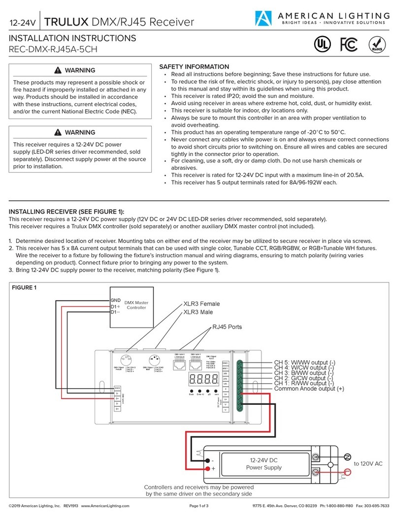
INSTALLING RECEIVER (SEE FIGURES 1 and 2):
This receiver requires a 12-36V DC power supply (12V DC or 24V DC LED-DR series driver recommended, sold separately).
This receiver requires a Trulux Radio Frequency controller or Trulux WiFi Hub for operation (both sold separately).
1. Determine desired location of receiver. Mounting tabs on either end of the receiver may be utilized to secure receiver in place via screws.
2. This receiver has 4 x 5A current output terminals that can be used in conjunction with Trulux Radio Frequency controls to control single color,
Tunable CCT, RGB, and RGB+WW fixtures. Wire the receiver to a fixture by following the fixture’s instructions manual and wiring diagrams,
ensuring to match polarity (wiring varies depending on product). Connect fixture prior to bringing any power to the system.
3. Bring 12-36V DC supply power to the controller, matching polarity (See Figure 1).
Note: To establish a Master/Satellite system where one ‘master’ receiver instructs multiple connected ‘satellite’ receivers to respond in sync,
bring 12-36V DC supply power to each receiver and interconnect as shown in Figure 1. On the input side of each receiver, there is a black
plastic cover over two pins; pull this black cover o to set master vs satellite. A closed circuit (cap is covering both pins) sets the master and an
open circuit (cap is covering only 1 pin) sets the satellites (See Figure 2). After installing the master/satellite system, the master receiver will need
to be powered On/O once for the mater function to take eect.
RF RECEIVER
RF RECEIVER
12-36V DC
Power Supply
Controllers and receivers may be powered
by the same driver on the secondary side
WARNING
WARNING
FIGURE 1
LN
whit e
1234
Learning Key
whit e
1234
Learning Key
to 120V AC
Mounting tabs
+
+
-
-
FIGURE 2
Closed Circuit
(Master)
Pins
Cap
Open Circuit
(Satellite)
Master/
Follower
Switch
DC INPUT
12/36 VDC
V+
V-
Learning
Switch
Rese t
Switch
CH 1: R/WW output (+/-)
CH 2: G/CW output (+/-)
CH 3: B/WW output (+/-)
CH 4: W/CW output (+/-)
Learning
Key


