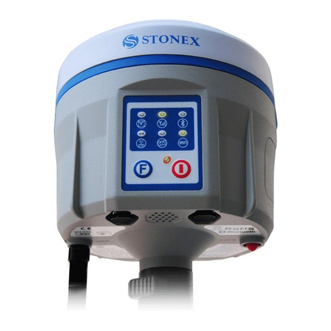
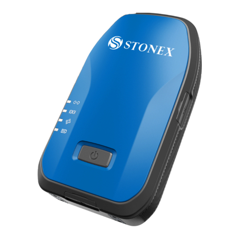
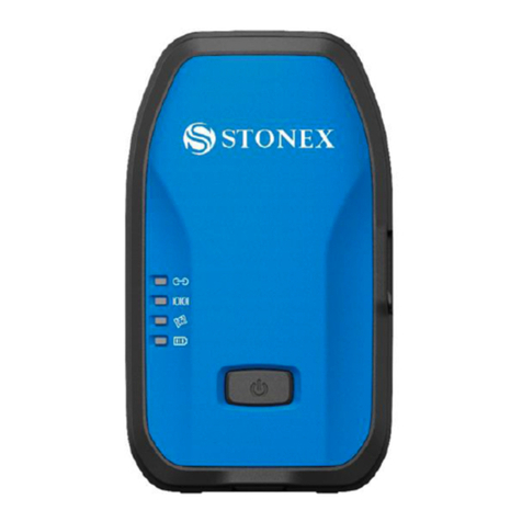
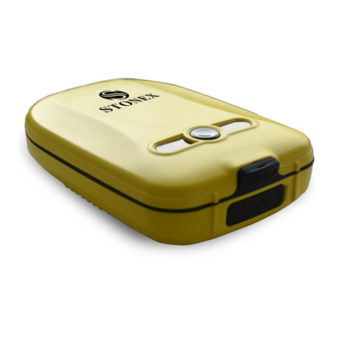
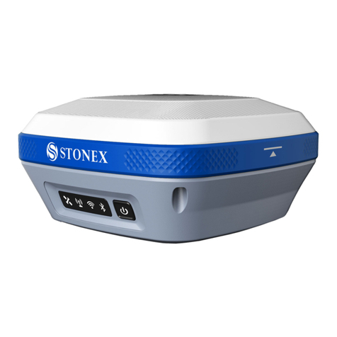
STONEX S800A User manual

(September 2017)-Ver.1-Rev.0 –Firmware Version: 0.22.170401
www.stonex.it
STONEX S800A
GNSS Receiver
User Manual
NEX S800A
GNSS Receiver
User Manual

S800A GNSS Receiver –User Manual 1
Contents
1. Brief Introduction ........................................................................................ 3
1.1 Introduction ...................................................................................................................3
1.2 Features ...........................................................................................................................4
1.3 Precaution.......................................................................................................................4
2. S800A Surveying System ............................................................................ 5
2.1 S800A Receiver .............................................................................................................5
2.1.1 Receiver appearance...............................................................................................5
2.1.2 The bottom of Receiver.........................................................................................5
2.1.3 Control Panel .............................................................................................................6
2.1.4 Mode View and Mode Switch.............................................................................9
2.1.5 Receiver Self-check..................................................................................................9
2.2 Standard Accessories ..............................................................................................10
2.2.1 Transport container..............................................................................................10
2.2.2 Adaptor ..................................................................................................................... 10
2.2.3 UHF Antenna...........................................................................................................11
2.2.4 7-pin Serial Cable..................................................................................................12
2.2.5 Other Accessories.................................................................................................. 13
3. Field Surveying........................................................................................... 14
3.1 Static Surveying.........................................................................................................14
3.1.1 Static Surveying Introduction........................................................................... 14
3.1.2 Static Surveying Operation ............................................................................... 15
3.1.3 Design Principles of GPS Control Network ................................................16
3.1.4 Data acquisition method....................................................................................16
3.2 RTK Dynamic Measurement (Radio).................................................................17
3.2.1 Installation of Base ............................................................................................... 17
3.2.2 Start of Base ............................................................................................................18
3.2.3 Installation of Rover............................................................................................. 18
3.2.4 Configuration of Rover .......................................................................................19
3.3 RTK Dynamic Measurement (Network) ...........................................................20
3.3.1 Installations of Base and Rover ....................................................................... 20
3.3.2 Configuration of Rover .......................................................................................20
4. Web UI Application ................................................................................... 21
4.1 Status .............................................................................................................................22
4.2 Settings .........................................................................................................................23
4.3 Download.....................................................................................................................24
4.4 Management ..............................................................................................................24
4.4.1 Device Register....................................................................................................... 25

S800A GNSS Receiver –User Manual 2
Appendix 1: S800A Receiver Specification ............................................................ 26
Appendix 2: Default Radio Configuration..............................................................28
Appendix 3: Copyrights, warranty and environmental recycling................. 29
Appendix 4: Safety Recommendations...................................................................37

S800A GNSS Receiver –User Manual 3
1. Brief Introduction
1.1 Introduction
Thank you for choosing our products. STONEX®, as a leading RTK
manufacturer, is committed to providing the most advanced GNSS surveying
tools.
This manual applies to S800A products, containing instructions for installing,
configuring the product and operating it. Even if you have used other RTK
products of ours before, we recommend that you spend some time reading
this manual for better user experience.
S800A is a superminiature GNSS RTK receiver of STONEX®. With brand-new
appearance design and solid magnesium alloy structure, it supports GPS,
GLONASS, BeiDou 2nd generation and Galileo satellite navigation system,
which meets accuracy demands of modern surveying to provide reliable
surveying results and user friendly operation. S800A brings you the utmost
experience.
One new features inside S800A is Atlas reception : Atlas is a differential
corrections systems broadcasted on L-Band, allowing increase in position
accuracy in area not covered by conventional Cors working under Ntrip
Technology ( lack of reference stations, lack of GPRS signals, etc ). Atlas is
broadcasted by satellite systems ,so the reception is nearly ensured all over
the world . Atlas uses similar technology compared to SBAS, but providing
better positioning accuracy.

S800A GNSS Receiver –User Manual 4
1.2 Features
Multi-constellation system. Supports BeiDou, GPS, GLONASS and Galileo
multi-system navigation and positioning.
Compact and convenient. High integration.
IP67 Waterproof and Dust Proof Rating. Shock resistant.
Highly integrated internal antenna. Zero phase center offset.
Onboard 8G memory.
Powerful battery endurance with over 10 hours’ continuous
operation.
1.3 Precaution
Transportation:during the transport, the receiver and its accessories must
be reasonably placed in its transport container, to protect against shock and
vibration. Specially note that S800A contains a non-removable internal
Lithium Battery, whose national and international regulations must be
observed and fulfilled in transportation.
Storage: before storage, discharge battery below 30%. After storage
recharge batteries before using. A proper storage temperature in a dry
environment is recommended to minimize self-discharging of the battery.
Keep the receiver dry in storage and before using.
Cleaning and Drying: use only a clean, soft, lint-free cloth for cleaning. If
necessary, moisten the cloth with water or pure alcohol. In all kinds of
weather conditions, after coming back from the field, dry the product, the
transport container, the foam inserts and the accessories. Pack them after
they have dried. Keep plugs clean and dry. Wet connectors must be dry
before attaching the dust cap.

S800A GNSS Receiver –User Manual 5
2. S800A Surveying System
S800A surveying system consists of three main components, namely receiver,
handheld and accessories. In the following parts are their introductions.
2.1 S800A Receiver
2.1.1 Receiver appearance
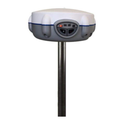
The receiver’s dimension is 146mm*146mm*76mm, weighting 1.2kg, with its
appearance as illustrated in Figure 2-1. The front side is control panel,
consisting of 1 power button and 4 indicators. The bottom are interfaces of
UHF antenna and cables.
Figure 2-1 S800A Receiver
2.1.2 The bottom of Receiver
At the bottom of the receiver is labelled system-unit serial number. The
bottom interfaces are illustrated in Figure2-2, with covers for dust and water
prevention.

S800A GNSS Receiver –User Manual 6
Figure 2-2 Receiver bottom
TNC interface: connect internal radio antenna.
2-pin LEMO port: charge for internal battery, connect adaptor.
5-pin LEMO port: connect external power supply and external radio
7-pin LEMO port: connect PC or handheld, USB+serial port
2.1.3 Control Panel
Control Panel is illustrated in Figure 2-3.

S800A GNSS Receiver –User Manual 7
Figure 2-3 Control Panel
Function descriptions of power button and indicators are shown in Table 2-1.
Table 2-1 Indicator function description
Indicator
Status
Description
Power button
On: sufficient
power
Fast flashing
(1s): low power
(below 10%)
Slowly flashing
(3s): charging
When the S800A receiver is powered on,
the power indicator will be lit. According
to battery power, the power indicator
shows the following three different
statuses:
1. On (Green): sufficient power supply
2. Fast flashing: power below 10%,
indicator flashing once per second
3. Slowly flashing: charging, indicator
flashing once per 3 seconds
Note: Most often, when power indicator
is fast flashing, the internal battery can
support receiver to continuously work for
only 1 hour. The indicator shows both
statuses of internal battery and external
power, and when the receiver connects to
external power, the indicator will
automatically switch to showing status of
external power.

S800A GNSS Receiver –User Manual 8
Satellite led
Blink: Lock
satellites
Off: invalid
solution (Lock
no satellite)
This led shows the amount of locked
satellites. When the receiver locks more
than one satellite, the led will start
flashing in a loop per 30 seconds,and
the number of flashes is the number of
the satellites locked by the receiver.
When the receiver locks no satellite, it’s
off.
Data link led
Flashing: data is
transmitting
When the receiver starts to transmit or
receive data, the led starts flashing.
WIFI led
On: WIFI on
Off: WIFI off
When WIFI is on, the led is lit green.
When the WIFI is off, the led is off.
Bluetooth led
On: Bluetooth
has connected.
Flashing:
Bluetooth has
connected and
is receiving
differential
data.
Off: no
connection
When receiver is connected to handheld
or other instruments by Bluetooth, the
led will be lit blue.
When receiver has connected to other
instruments by Bluetooth and is receiving
differential data, the led will be flashing.
When receiver doesn’t use Bluetooth, the
led won’t be lit.

S800A GNSS Receiver –User Manual 9
2.1.4 Mode View and Mode Switch
a) Mode view
When receiver is powered on, flip the power button and then it will voice
broadcast the current working mode and data link.
b) Mode switch
When the receiver is powered on, connect it with handheld or other
instruments so as to set up and switch the working mode of receiver. See
detailed operation procedures in Cube-a User Manual.
2.1.5 Receiver Self-check
Self-check functionality is to check whether every module works normally.
When S800A receiver has indicators off or module doesn’t work normally,
you can use self-check to inspect the receiver. S800A self-check consists of
four parts, namely GPS, radio, WIFI and Bluetooth. The self-check results will
be voice broadcasted in the process. Self-check operation and result
broadcast are as followed:
a) When receiver is powered on, press power button and hold it until
the receiver voice broadcasts “power off”. Press it again until the receiver
sounds a beep and voice broadcasts “self-check”, which means the receiver
starts to operate self-check. (New receiver is recommended to operate self-
check at least once.)
b) In the process of self-check, each module inspection is followed by
its inspection result. If the module inspection passes, it will voice broadcast
“OK” and module led keeps on until the whole self-check finishes. If the

S800A GNSS Receiver –User Manual 10
module inspection fails, it will voice broadcast current module inspection fail,
keep module led flashing and buzzer sounding until you restart the receiver.
Self-check lasts for about 1 minute. If there is self-check failure, please
contact local dealer.
c) If every module indicator is lit with no flashing, and voice broadcast
says every module work normally (such as “GPS self-check. OK.”), it means all
the modules work normally. Receiver starts to work after the whole self-
check finishes.
2.2 Standard Accessories
2.2.1 Transport container
There are two kinds of S800A containers: Rover container and Base
container. These two containers have similar appearances but their insert
layouts are different. (S800A containers are still under production.)
2.2.2 Adaptor
S800A receiver adopts internal battery. You can use adaptor to charge the
receiver. S800A receiver and handheld share the same adaptor model as
illustrated in Figure 2-12.

S800A GNSS Receiver –User Manual 11
2.2.3 UHF Antenna
When receiver is in internal radio mode, UHF antenna (as illustrated in Figure
2-15) is in need.
Figure 2-15 UHF antenna
UHF antennas have 3 models, respectively covering 3 frequency ranges as
shown in Table 2-6.
Table 2-6 UHF antenna models
Model
QT410A-1
QT440A-1
QT450A-1
Frequency (MHz)
410~430
430~450
450~470

S800A GNSS Receiver –User Manual 12
2.2.4 7-pin Serial Cable
One end of the 7-pin serial cable, the 7-pin serial port, is to connect the
receiver, and the other end of the cable, the USB and the D89 interface are
for data communication respectively with PC and handheld as illustrated in
Figure 2-16.
Figure 2-16 7-pin serial cable

S800A GNSS Receiver –User Manual 13
2.2.5 Other Accessories
Other accessories include glass mounting pole, controller holder, connector,
tray and measuring tape and other accessories.
Figure 2-17 Glass fiber mounting pole Figure 2-18 Controller holder
Figure 2-19 Connector Figure 2-20 Tray Figure 2-21 Measuring tape

S800A GNSS Receiver –User Manual 14
3. Field Surveying
3.1 Static Surveying
3.1.1 Static Surveying Introduction
Static Surveying is an GPS positioning measurement by installing three or
more GNSS receivers at different measuring stations to measure
simultaneously so as to get the relative positions of measuring stations.
Scope of application:
•the establishment of national geodetic control network (second or the
following class)
•the establishment of precise engineering control network, such as
bridges measurement, tunnel measurement
•the establishment of various densified control network, such as city
measurement, mapping control point measurement, road measurement
and boundaries location.
•GPS measurements including control survey used for mapping, cadastral
surveying, land information, real estate surveying, geophysical
prospecting, surveying and building construction in small and medium-
sized cities and towns, which should meet the accuracy demand of D or
E class GPS measurement.

S800A GNSS Receiver –User Manual 15
3.1.2 Static Surveying Operation
a. Set up the tripod at the measuring station, switch the receiver to
static mode and attach it to the tribrach, centering and leveling it in strict
standard.
b. Measure the height of antenna.
c. Record names of station and receiver, height of receiver,
measurement start time, measurement end time, observation session and
satellite number.
d. Static data logging: Power on the receiver and make sure it’s in
static mode. Receiver starts to search satellites and satellite led starts to be
flashing. When it meets the record demand, the satellite led will be flashing
at default sampling interval, and one flash represents having logged an
epoch.
e. Power off the receiver after finishing data logging, and then transmit
the data and do the indoor data processing. (See detailed operation
procedures in Cube-a Software (V3.0) User Manual.)

S800A GNSS Receiver –User Manual 16
3.1.3 Design Principles of GPS Control Network
(1)In order to ensure the continuous tracking observation of satellites and
quality of satellite signal, set up the GPS measuring station in locations which
are free of obstructions, where the altitude angle of obstacles should be less
than 15°in the field of view.
(2)In order to reduce or avoid interruption from electromagnetic wave to
satellite signal, set up the measuring station away from high-power radio
source (such as television station, broadcasting station and microwave
station). And there should be no object nearby that can strongly reflect
satellite signal (such as large-scale buildings).
(3)Measuring station should have convenient transportation and stable
ground foundation, easy for state holding and beneficial for extension of
other measuring method and joint measurement.
3.1.4 Data acquisition method
There are 2 acquisition methods of data: manual start and automatic start.
Open the Cube-a software on the handheld, click “Device” –
“Communication”, choose the receiver model and the communication mode.
There are Bluetooth and WIFI two communication modes.
a. Manual start
Click “Device” - “Working mode”, choose “Static”. At here, you can configure
static parameters, antenna parameters and satellite system.
b. Automatic start
Click “Device” - “Working mode”, choose “Static”. At parameter settings,
choose auto record static data and at the next time when the receiver is

S800A GNSS Receiver –User Manual 17
powered on, it can automatically start static data logging with no need to
reset.
3.2 RTK Dynamic Measurement (Radio)
RTK dynamic measurement (base and rover) has radio mode and network
mode, which two differs from each other in their ways of transmitting
differential signal.
3.2.1 Installation of Base
(1)Set up the tripod in location with known coordinates or unknown
coordinates, level it and attach the receiver on it.
(2)Set up the receiver according to the chosen data link. If using the
internal radio transmission, attach the internal radio antenna into the UHF
antenna port of receiver; if using external radio transmission, connect the
external radio to 5-pin port with 5-pin cable.
(3)Power on the receiver and select base mode.

S800A GNSS Receiver –User Manual 18
3.2.2 Start of Base
Open Cube-a on the handheld to choose communication mode. Click
“Device” - “Working mode” to choose base mode and configure its start up
mode, parameters, data link and satellite system and other settings.
Base has 2 start up modes.
a. Use Current Coordinates
Base uses approximate WGS-84 coordinates of current location as base
coordinates.
b. Input Base Coordinates
User specified base coordinates: the specified base coordinates cannot be far
away from the precise WGS-84 coordinates of the current location, otherwise
the base cannot work.
3.2.3 Installation of Rover
After the installation of base, start to install rovers.
(1)Fix the bracket on the pole, fix the handheld to the bracket and then
install the rover on the pole.
(2)Attach the internal radio antenna or connect the external radio
according to the chosen data link.
(3)Power on the receiver and select rover mode.

S800A GNSS Receiver –User Manual 19
3.2.4 Configuration of Rover
Open Cube-a software on the handheld to choose communication mode.
Click “Device” - “Working mode” to choose rover mode and configure its
data link, antenna parameters and satellite system and other settings. When
data link is internal radio, you need to configure the radio channel,
frequency, protocol and power.
Note:
1. If you want an high-precision surveying result (several cm), it’s
recommended to use a tripod to install rover;
2. When the coverage of surveying area is large (over 4 km from base),
the working distance too far for internal radio to meet the demand, it’s
recommended to use external radio to connect the receiver;
3. Under radio mode, frequency and protocol settings of base and
rover should be the same.
Table of contents
Other STONEX Receiver manuals
STONEX
STONEX S900 User manual
STONEX
STONEX S9III Plus User manual
STONEX
STONEX SC2000 User manual
STONEX
STONEX SC2200 User manual

STONEX
STONEX S9III GNSS User manual
STONEX
STONEX S900+ User manual
STONEX
STONEX SC600 User manual
STONEX
STONEX S900T User manual
STONEX
STONEX S9i User manual
STONEX
STONEX S9 GNSS User manual
