American Plumber WRO-2550 User manual

Technical Support: 1-800-279-9404 (M-F 7:30 am - 5:00 pm CST)
4-Stage Reverse Osmosis Water Filtration System
Installation and Operating Instructions
Model WRO-2550
IMPORTANT: Before installing this reverse osmosis system, make
certain your water supply complies with the following operating
specifications. Failure to do so may reduce the effectiveness of the
system and will void the warranty.
Specifications
Thin Film Membrane: TFM-50
Feed Water Pressure: 40 to 100 psi (2.75–6.9 bar)
Temperature Range: 40–100°F (4.4–37.7°C)
TDS: 2000 ppm
Maximum Hardness†: 10 gpg (171 mg/L)
Sulfide, Iron and Manganese‡: 0 ppm <0.1 ppm
Chlorine in Water Supply: Less than 2 ppm
pH Limits: 3–11
Daily Product Water Rate: 15.04 gpd (56.93 Lpd)
TDS Rejection: 96.2%
Turbidity: 11 NTU Average
†If the hardness of your water is above 10 gpg (171 mg/L), lime scale
will build up rapidly on the membrane. Scale buildup will plug the
membrane and make the system ineffective. We do not recommend
these reverse osmosis systems to be used with water in excess of
10 gpg (171 mg/L) hardness.
‡A maximum total level of approximately 0.01 ppm sulfide, iron or
manganese is permissible. See your local dealer to reduce these
substances in your water.
Tested by NSF International according to NSF/ANSI Standard 58 has
given 15.04 gallons per day. Source water test parameters are 50 psig,
77°F, pH of 7.5 ± 0.5 and 750 ppm total dissolved solids.
Parts Included: (See back of manual for diagram)
Pre-assembled filter system (mounting bracket, membrane housing,
membrane, pre- and post-filter housings and pre- and post-filter
cartridges).
• Reverseosmosismembrane •Storagetank
• Inletsupplyadapter •Chromefaucet
• Drainclamp •Feedtubing
• 1/4-inchTubing •Sumpwrenches
• Tankvalve •3/8-inchTubing
System Dimensions:
Overall Dimensions: 131⁄2-inch W x 51⁄2-inch D x 171⁄4-inch H
(34.29 cm W x 12.7 cm D x 43.8 cm H)
Weight: 17.3 lbs. (7.84 kg)
Tank Dimensions: 131⁄2-inch W x 9 inch D x 9 inch H
(34.29 cm W x 22.86 cm D x 22.86 cm H)
Tank Capacity Max: 2.8 gal. (10.6 L)
Tank Air Pressure Empty: 5 to 7 psi (0.34 to 0.48 bar)
Tank Weight (Full): 28.5 lbs. (12.9 kg)
The WRO-2550 is Tested and Certied by NSF International against
NSF/ANSI Standard 58 for the reduction of Total Disolved Solids,
Fluoride, Turbidity, Lead, Selenium, and Copper.
Tools and Materials
Required
• Hand or electric drill
(cordless preferred)
• (2) Adjustable wrenches
• Slotted and Phillips
screwdrivers
• File
• Safety glasses
• Drill bits: 1/8", 3/16", 1/4", 3/8"
If sink does not have hole for
separate faucet:
• Center punch
• Cone-shaped grinding wheel
• 1-1⁄4" hole saw or drill bit
• Safety mask
NOTE: All tools may not be
necessary for installation. Read
installation procedures before
starting to determine what tools
are necessary.
SH247244 Rev A FE11

GENERAL
WARNING:
Do not use with water that is microbiologically unsafe
or of unknown quality without adequate disinfection before or after
the system.
CAUTION:
Filter must be protected against freezing, which can
cause cracking of the filter and water leakage.
CAUTION:
Because of the product’s limited service life and to
prevent costly repairs or possible water damage, we
strongly recommend that the bottom of all plastic
housings be replaced every five years for clear and ten
years for opaque. If the bottom of your housing has been
in use for longer than this period, it should be replaced
immediately. Date the bottom of any new or replacement
housing to indicate the next recommended replacement
date.
NOTE:
•Yourwatermustbewithinrequiredlimitsforsatisfactoryoperation.
If not, your membrane life may be shortened and your warranty will
be voided (see Specifications on page 1).
•Thisreverseosmosissystemwillnotprotectagainstdisease-
causing bacteria or remove naturally-occurring harmless bacteria.
•Installoncoldwaterlineonly.
•Donotusewickingorsealertotconnectionsintothecapofthe
filter. Teflon®tape is recommended.
•Makecertainthatinstallationcomplieswithallstateandlocallaws
and regulations.
•Thereplacementcartridgesandreverseosmosismembrane
included with this system have limited service lives. Changes in
taste, odor, and color of the water being filtered indicate that the
cartridge should be replaced (see Replacing the Pre- and Post-
Filters on page 8, and Replacing the Membrane, on page 9).
•Afterprolongedperiodsofnon-use(suchasduringavacation)itis
recommended that the system be flushed for 5 minutes before it is
used.
•Adrinkingwatercartridgemaycontaincarbonnes(veryneblack
powder). After installation, flush the system for 5 minutes to remove
the carbon fines before using the water.
•Itisrecommendedthatyourunthetapatleast20secondspriorto
using water for drinking or cooking purposes.
•Thecontaminantsorothersubstancesremovedorreducedbythis
water treatment device are not necessarily present in your water.
RO MEMBRANE PRECAUTIONS
CAUTION:
Chlorine will destroy the TFM-50 membrane. If you use the
WRO-2550 with a chlorinated or periodically-chlorinated
watersupply,itisABSOLUTELYNECESSARYtousea
carbon pre-filter (included with the system). This carbon
pre-filter should be changed at least every 3 months to
avoid chlorine bypass. See Warranty for disclaimers and
limitations that apply to the TFM-50 membrane.
NOTE:
•Tomakesurenochlorineispresentinthewaterthatreachesthe
membrane, you may want to use a chlorine test kit to check the
brine/reject water that flows from the membrane to the drain. No
chlorine should be detected.
•TheTFM-50membraneisresistanttonaturally-occurringbacteria.
HOW REVERSE OSMOSIS WORKS
The WRO-2550 Reverse Osmosis (RO) System uses a semi-permeable
membrane to reduce dissolved salts and minerals, improving the
taste and odor of your water. The RO membrane is made of layers of
micron-thin film wound around a hollow center core. Water molecules
can pass through the membrane, but dissolved salts and minerals are
rejected.
The WRO-2550 Reverse Osmosis System features 4-stage filter action.
Yourwatersupplyispre-lteredtoreducedirtandchlorinethatmay
foul the membrane. The RO membrane separates this pre-filtered
water into PRODUCT WATER and DRAIN or REJECT WATER. Incoming
water pressure forces the product water through the membrane
and into the storage tank. Dissolved solids and other contaminants
cannot pass through the membrane and are sent to the drain as reject
water. When you open the drinking water faucet, product water is
drawn from the storage tank through an activated carbon post-filter,
providing you with cleaner, great-tasting water.
For each gallon of water produced, several gallons are discharged
as reject water. The storage tank can hold up to 2.8 gallons (10.6 L)
of water at a time, for drinking and cooking needs. When used under
the Specifications on page 1 of the manual, your Reverse Osmosis
membranes should last 12-24 months.
BASIC INSTALLATION PROCEDURE GUIDELINES
•Forstandard,under-sinkinstallationon3/8-inch(10mm)steel,brass,
or copper cold water line.
•Pleasereadallinstructionsandprecautionsbeforeinstallingand
using your WRO-2550.
•Numbereddiagramscorrespondwithnumberedsteps.
Precautions
2

Installation
• ReadallinstallationandoperatinginstructionsbeforeinstallingandusingyourROsystem.
• Numbereddiagramscorrespondwithnumberedsteps.
1. Installing the Water Supply Adapter
The supply adapter fits 1/2-inch 14 NPS threads. If local codes permit, it may be used to
connect the WRO-2550 to the cold water supply line. If local codes do not permit the use
of the supply adapter, alternate connectors can be obtained from your local plumbing
wholesaler.
Directions:
(A) Turn off cold water inlet supply line. If cold water line does not have a shut-off valve
under the sink, you should install one.
(B) Turn on the cold water faucet and allow all water to drain from line.
(C) Disconnect cold water line from 1/2-inch 14 NPS threaded stub on bottom of main
faucet.
(D) Using the nut that previously connected the cold water line to the faucet, screw the
cold water line to the male supply adapter threads.
2. Selecting the Faucet Location
The drinking water faucet should be positioned with function, convenience and
appearance in mind. An adequate flat area is required to allow faucet base to rest securely.
The faucet fits through a 11⁄4-inch hole. Most sinks have pre-drilled 11⁄2-inch or 13⁄8-inch
diameter holes designed for spray hoses. The drinking water faucet may be installed using
one of these holes, despite their larger size. If these pre-drilled holes cannot be used or are
in an inconvenient location, it will be necessary to drill a 11⁄4-inch hole in the sink or through
countertop next to the sink for the faucet.
CAUTION:
This procedure may generate dusts which can cause severe irritation if inhaled
or come in contact with the eyes. The use of safety glasses and safety mask for
this procedure is recommended.
CAUTION:
Do not attempt to drill through an all-porcelain or porcelain-coated sink. For
applications on these types of sinks we recommend using the sprayer hole or
mounting the faucet through the countertop.
CAUTION:
When drilling through a countertop make sure the area below the drilled area
is free of wiring and piping. Make certain that you have ample room to make
the proper connections to the bottom of the faucet.
CAUTION:
Do not drill through a countertop that is more than 1 inch thick.
CAUTION:
Do not attempt to drill through a tiled, marble, granite or similar countertop.
Consult a plumber or the countertop manufacturer for advice or assistance.
The following instructions apply to stainless steel sinks ONLY.
(A) Line bottom of sink with newspaper to prevent shavings, parts or tools from falling
down the drain.
(B) Place masking tape over the area to be drilled to help prevent scratches if drill bit slips.
(C) Mark point with center punch. Use a 1/4-inch drill bit to drill a pilot hole through sink.
(D) Use a 11⁄4-inch hole saw to enlarge hole. Smooth rough edges with a file.
3. Mounting the Faucet
(A) Loosen stem-nut on faucet, remove metal slotted disc (if attached).
(B) Attach large diameter 3/8-inch drain tube to barb fitting at the faucet base. This tube
should be long enough to reach the drain clamp in Step 4.
(C) Attach small diameter 1/4-inch drain tube to other barb fitting at faucet base. This tube
should be long enough to reach right side of the RO Assembly.
(D) Slide chrome plate and black rubber washer onto faucet by threading both drain tubes
through the holes on the plate and washer.
(E) Slide white extension onto long threaded section of faucet. Open end of extension
should come in contact with base of faucet.
(F) Apply 3-5 wraps of Teflon tape to faucet stem. Screw quick connector onto end of
threads.
(G) Wet end of 3/8" tube. Push into bottom of connector. Tug gently to be sure connection is
complete.
NOTE: To remove the tube, push on the fittings' collar and pull the tube out.
(H) Holding the faucet, feed the three tubes through the hole in the sink. Position the
faucet handle at a desired location.
D
1
A
B
C
D
D
C
1⁄4”
11⁄4”
A
B
C
D
Pilot Hole
Mounting
Hole
11⁄4"
1/4"
2
3
Counter Top
B
C
D
E
G
F
I
A
3

Installation Continued . . .
(I) Center the faucet and slip slotted disc between the white extension and the bottom of
the counter or sink. Tighten the stem nut with a wrench until it is tight.
(J) Firmly insert goose-neck spout into faucet base.
4. Installing the Drain Clamp
NOTE: If you have a single-basin sink with a disposal unit, call Technical Support for
options.
NOTE: Before installing the drain clamp, check the drainpipes under the sink for corrosion.
Corroded pipes should be replaced before continuing with installation.
(A) Attach the drain clamp to a vertical section of the drainpipe, about 6 inches above
the trap. Make sure the opening on the drain clamp is facing towards the drinking water
faucet (see diagram on previous page).
(B) Using the fitting hole of the drain clamp as a guide, drill a 1/4-inch hole through one side
of the drainpipe.
(C) Remove the drain clamp from the drainpipe and enlarge the hole with a 3/8-inch drill bit.
Use a file to remove rough edges from the drilled hole.
(D) Make sure the black rubber gasket is adhered to the inside of the drain clamp and
place the drain clamp assembly over the drilled hole. Look through the hole and position
the clamp so that the center of the clamp hole is slightly higher (about 1/16-inch) than
the center of the drilled hole. Tighten the clamp securely.
(E) Screw the plastic compression nut onto the drain clamp until hand-tight.
5. Connecting the Faucet to the Drain
CAUTION:
This is a gravity drain line. Any loops, kinks or sharp bends must be eliminated
before proceeding. Failure to create a straight line to the drain may result in
reject water leaking through the air gap in the faucet onto the countertop and
below the faucet.
(A) Align the larger reject (3/8-inch) tubing from the faucet with the compression nut on the
drain clamp. Create as straight and smooth a path as possible with the tubing. Do not
kink tube. Cut the tubing squarely below the nut and remove the internal and external
burrs.
(B) Loosen the compression nut two complete turns. Insert the tubing into the nut until
it stops. Tighten with fingers, then tighten 1 to 2 turns with a wrench.
6. Installation of Mounting Screws
(A) If system is being installed under the kitchen sink, locate it on back or right wall.
Make sure to allow ample space for installation. To change the filter cartridges,
a minimum of 11⁄2-inches of clearance is required underneath the filter housings.
A minimum of 2 inches of clearance from the left side of the unit is also required or
5 inches from the left bracket mounting screw hole.
(B) Install mounting screws at least 15 inches from cabinet floor and 71⁄2-inches apart.
Leave a 5/16-inch space between the head of the screw and the wall to slip bracket
onto screws.
NOTE: Each connection fitting on the RO Assembly has a plug that must be removed
before inserting tubing. Push in on the collar and pull the plug out.
7. Connecting the Faucet to the System
(A) Locate the reject tubing (reject water line) from the drinking water faucet. This tube is
the smaller of the two. Place a mark on the tubing 5/8-inch from the end. Moisten the
end of the tubing with water and insert tubing into the quick-connect fitting on the flow
restrictor found on the right side of system behind the membrane.
If tubing is not firmly connected, leaking will occur. It is important for the tubing to be
inserted all the way until the mark is flush with the outer edge of the quick-connect insert.
NOTE: Tubing may be quickly and easily removed from the fitting if necessary by pressing
the collar around the fitting then pulling the tubing with your other hand.
(B) The faucet tube from the bottom of the threaded metal tube is inserted into the post
filter. The fitting is at the top left of the RO System. Push the free end of the tubing into
the quick connect fitting.
4
A
BC
6"
D
E
5A
B
3/8" Tube
65" (min.) 71⁄2"
15"
(min.)
11⁄2" (min.)
2" (min.)
7
A
B
Port Reference
4

Installation Continued . . .
8. Connecting the Storage Tank to the System
CAUTION:
When tank is full, it weighs approximately 28.5 lbs. (12.9 kg) Provide ample
support under the tank.
(A) To prevent leaks, apply 3 or more wraps of Teflon tape to threads on tank. Thread the
tank valve onto the top of the tank opening. Turn tank so handle is in line with tubing.
CAUTION:
The tank /valve connection will leak if not properly sealed. Teflon tape will
normally seal the threaded connection.
(B) Locate the 1/4-inch tubing. Place a mark on the tubing 5/8-inch from each end. Moisten
one end of the tubing with water and insert with a twisting motion into the port of the
tank valve until the 5/8-inch mark is flush with the quick connect fitting. Then locate the
tank near the system's installation area.
(C) Cut the tubing to correct length. Install free end of tubing into white quick-connect
fitting on the post filter tee on the right side. Do not cut tubing.
(D) Place entire system over mounting screws on wall and slide down.
CAUTION:
Make certain system is firmly attached to wall to prevent it from falling and
possibly becoming damaged.
NOTE: Use caution not to bend or pinch the tubing behind the system while attaching to
mounting screws.
9. Connecting the Supply Adapter and Inlet Filter
(A) Locate remaining length of 1/4-inch plastic tubing.
(B) Push into quick connect fitting on the right side of system.
(C) Cut the tube to a length that will allow connection to the cold water supply fitting.
Ensure the tubing does not kink. Push the tube into the fitting.
10. Installing the Membrane
(A) Remove tube attached to membrane housing by pressing in the white collar around the
fitting while pulling the tubing with your other hand.
(B) Hold the membrane housing with one hand and turn the cap (wrench provided) with
other hand to remove. To make it easier to hold the membrane housing, you may want
to remove the post-filter.
(C) With clean hands (sanitary gloves preferred), remove the membrane from the plastic
bag. HANDLE WITH CARE.
CAUTION:
Do not unwrap the tape around the membrane, as it is part of the membrane.
Do not squeeze membrane.
(D) With the double O-ring side first, push membrane into housing until it stops.
About 1/8-inch of the membrane’s plastic core will stick out beyond the housing.
(E) Use clean silicone grease (pack is included with the system) to lubricate both O-rings
and the brine seal. Hand-tighten membrane housing cap until you feel resistance, then
tighten an additional 1/2 turn. Do not over-tighten.
(F) Reinsert the tube by pushing it into the quick connect fitting.
B
Port Reference
9A
C
1/4" Tube
5/8"
16 mm
5/8"
16 mm
10
A
A
D
E
Port Reference
Port Reference
C
8A
B
1/4" Tube
Apply
Teflon tape
5/8"
5

Installation Continued . . .
11. Faucet Operation
(A) For controlled water flow, push the handle down.
(B) For constant water flow, lift the faucet handle to lock it in the open position.
12. System Start-up
NOTE: The reverse osmosis membrane is treated with a food grade sanitizing agent
that may cause an undesirable taste. Although it is not harmful, it should be
flushed from the system.
NOTE: The post-polishing filter may contain fine black carbon particles. These fines are
harmless, but may make the water appear gray in color. The carbon fines are
flushed from the system with the first tank full of water.
NOTE: The RO system does not produce a high volume of water on demand as an
ordinary filter does. Water is produced at a slow, drop-by-drop rate. The system
requires about 2 to 4 hours to fill the storage tank. As water is taken from the
tank, the system automatically starts the cycle of replacing the water and then
stops water production when the tank is full.
CAUTION:
Visually check the entire system for leaks.
If a leak is present, see
Troubleshooting on page 10.
(A) Turn off valve at top of storage tank.
(B) Turn on the cold water supply.
(C) Lift the faucet handle to lock it in the open position and let it drip for 30 minutes.
(D) Completely open the cold water supply until it comes to a stop. Allow water to drip from
the faucet for 12 more hours. Then close the faucet and open the valve on the storage
tank. The tank valve is open when the handle lines up with the tubing connection.
(E) Allow 2 to 4 hours for the tank to fill. Again, periodically check the installation for leaks.
After the storage tank is filled, open the faucet to flush the post-polishing filter. Allow 4
to 5 minutes for all of the water to drain from the tank.
(F) Close faucet and allow tank to fill.
(G) Repeat steps E and F four times.
NOTE: Initially, the water may appear cloudy. This is a result of air trapped in the post-
polishing filter. It is not harmful and will disappear in a matter of minutes. It may take up to a
week after installing a new post-polishing filter for the trapped air to dissipate.
Thesystemisreadyforoperation.YoucannowenjoyqualitywaterfromyourReverse
Osmosis System.
11
Push Down
Push Up
B
A
12 Closed
Tank Valve
B
A
Counter-
clockwise
Open
Tank Valve
6

Optional Installation
Connecting your Reverse Osmosis System to Refrigerator Icemaker /
Water Dispenser
CAUTION:
If you are connecting this unit to your refrigerator/icemaker with initial RO
installation, wait to turn on the icemaker until the post-polishing filter has been
flushed according to Step 12.
CAUTION:
Use plastic tubing and fittings. Do not use copper tubing or brass fittings.
NOTE:
For optimum performance, it is recommended that the distance between the RO system
and the refrigerator icemaker/water dispenser be no greater than 10 feet (3 m). At
distances greater than 10 feet, the water pressure from the system may not be adequate
to deliver water to the refrigerator.
MATERIALS REQUIRED (available from your local hardware store):
• 3/8-inchx3/8-inchx3/8-inch(0.952cmx0.952cmx0.952cm)compressionor
quick-connect tee
• 10feet(3m)of3/8-inch(0.952cm)polyethylenetubing
• Shut-offvalve
1. Turn off refrigerator water supply and icemaker (consult manufacturer’s guidelines).
2. Close tank valve (on top of storage tank).
3. Turn off water to RO system at the cold water supply.
4. Open drinking water faucet to relieve pressure.
5.
Locate tubing (permeate) leading to your drinking water faucet. Cut and insert the
3/8-inch
x
3/8-inch
x
3/8-inch
compression or quick-connect tee into the permeate
tubing.
Consult manufacturer’s guidelines before installing the supply adapter.
NOTE: When cutting the permeate tubing, you may experience some water leakage.
6. Using a length of 3/8-inch polyethylene tubing, connect the icemaker/dispenser line
with the free port on the compression tee.
7. The shut-off valve should be installed as close to this port of the tee as possible.
Shut-off valve should be installed in the OFF position. Consult manufacturer’s guidelines
before installing the shut-off valve.
8. Completely open cold water supply.
9. Open tank valve.
10. Turn off the drinking water faucet.
11. Turn on water to RO system at cold water supply.
12. Turn on icemaker and open shut-off valve. Consult manufacturer’s instructions.
13. Check for leaks and tighten connections if necessary.
Testing Your Reverse Osmosis System
Total Dissolved Solids (TDS) Test
NOTE: Under NSF/ANSI Standard 58, it is highly recommended that you (the consumer)
have your water tested at least every 6 months to verify that your system is
performing satisfactorily.
SAMPLING INSTRUCTIONS:
Sampling instructions are included with the Total Dissolved Solids (TDS) Test Kit. If the
TDS Test Kit is missing from your unit, please call Customer Support at 1-888-837-0028 for a
replacement.
When To Change The Cartridges
The life of the cartridge depends on the water volume used and the substances in the
water. Normally, cartridges should be changed at intervals of 6 months. Replace the
cartridge sooner if the water pressure at the faucet begins to drop noticeably or if you
notice changes in the taste, color, or flow of the filtered water.
Total Dissolved
Solids Test Kit
Tubing to drinking
water faucet
Tubing to
refrigerator
Tubing from system
outlet
5
7

1st Stage Pre-Filter and 2nd Stage Pre-Filter Cartridges:
The cartridge should be replaced every six months. If your
water contains a high amount of sediment, it may be necessary to
change the 1st stage cartridge more frequently. If your water contains
a high amount of chlorine, it may be necessary to change the 2nd
stage pre-filter more often.
1. Turn off incoming water supply and valve on the storage tank.
Place a tray under the system to catch any water that spills during
removal of the filter housings.
2.
Open faucet to release pressure.
3.
Unscrew bottom of filter housings from caps. Use the filter wrench.
Discard used cartridges.
4. Remove black rubber O-rings from grooves in housings. Wipe
grooves and O-rings clean; set O-rings aside.
5. Rinse out housings and fill each 1/3 with water. Add 2 tablespoons of
bleach and scrub with non-abrasive brush or sponge. Rinse thoroughly.
6.
Lubricate each O-ring with a coating of clean silicone grease. With
two fingers, press each O-ring securely into groove below the
threads of the appropriate housing.
CAUTION:
The rubber O-ring provides
the water-tight seal
between the cap and the
bottom of the housing.
It is important that
the O-ring be properly
seated in the groove
below the threads of
the housing or a water
leak could occur.
7. Insert cartridges in the bottom of the housings. Make sure
cartridge slips over standpipe in the bottom of the housing.
NOTE: Be sure to install cartridges in proper housings (see diagram below).
8. Screw bottoms of housings back onto caps securely; do not
over-tighten. Turn on cold water supply.
Check for leaks. Continue to check periodically to make sure
no leaks develop.
4th Stage Post-Filter Cartridge: post-filter should be replaced every
twelve months.
1. Turn off incoming water supply and valve on the storage tank.
Place a tray under the system to catch any water that spills during
removal of the filter housings.
2.
Open faucet to release pressure.
3. Remove filter from bracket and discard.
4. Remove tubes from fittings by pressing in collar around the fitting
while pulling the tubing out with your other hand.
NOTE:
If quick connect fittings need to be installed, tape threads of
fittings with 3 wraps of Teflon®tape and attach to filter.
CAUTION:
Ensure the tape is not touching O-ring on the fitting or a
leak may occur.
NOTE:
The filter has an arrow on it showing the direction of flow.
The tee fitting connects to the inlet side of the filter and the
elbow fitting attaches to the outlet side.
NOTE:
Hand tighten fittings, then tighten with wrench 1/4 turn.
5. Attach 4th stage filter to bracket with the tee fitting on the right
hand side.
6. Attach tubes to fittings by pushing in until the tube stops. Check to
see if tube is in place by trying to gently pull tube out.
Replacing the Pre-Filter and Post-Filter Cartridges
1/4" Feed Tube
1/4" Faucet
Drain Tube
3/8" Drain Tube
GS-10RO
(4th Stage Post-Filter)
TFM-50 Membrane
(3rd Stage Pre-Filter)
P5
(1st Stage
Pre-Filter)
EPM10
(2nd Stage
Post-Filter)
1/4" Storage
Tank Permeate
Tube
3/8" Faucet
Permeate Tube
8

About the Reverse Osmosis Membrane
When used under operating conditions specified on page 1 of the
manual, your reverse osmosis membrane should last at least one
year.Youshouldreplacethemembraneafter18to24months.Replace
it sooner if you notice a return of unpleasant tastes or odors or a
noticeable decline in water production. The precise life span of your
system's membrane will depend on the quality of the water entering
the system and the frequency with which you use it. Frequent system
use prevents the filtered salts and minerals from building up on
the membrane as scale. The more water the system is required to
produce,thelongerthemembranewilllast.Youmaywishtonda
variety of uses for your system in order to prolong the life of
the membrane.
During extended periods of non-use (such as during a vacation),
remove the membrane from the membrane housing and place it in
a sealed plastic bag. Store membrane in refrigerator for future use.
DO NOT FREEZE.
NOTE: If system stands for more than 2 to 3 days without being used,
the storage tank should be emptied.
Replacing the Membrane and Sanitizing the System and
Filters
NOTE: It is recommended that you sanitize the system each time
you change the membrane. It is not necessary to sanitize the
system when changing only the pre-filters or post-filter.
NOTE: When installing a new membrane, it is recommended that
you replace the pre-filter and post-filter cartridges as well.
Removing the Membrane and Filters
1. Turn off the cold water supply. Allow five minutes for system to
depressurize.
Place a tray under the system to catch any water that spills
during removal of the filter housings.
2. Open drinking water faucet to drain tank. When tank is drained,
close faucet.
3. Hold the membrane housing with one hand and remove the cap
with the other hand.
CAUTION:
Do not disconnect tubing from membrane cap.
4. To remove the RO membrane, grasp membrane tube with pliers
and pull. Discard old membrane. Screw cap back onto membrane
housing. DO NOT install new membrane.
5. Unscrew filter housings from caps and discard used cartridges.
6. Remove black rubber O-rings from grooves in housings.
Wipe grooves and O-rings clean; set O-rings aside.
Sanitizing the System
7. Rinse out bottom of housings and fill each 1/3 with water.
Add 2 tablespoons of household bleach to each housing and scrub
cap, bottom of housings, and membrane housing with non-abrasive
sponge or cloth. Rinse thoroughly.
8. Lubricate O-rings with a coating of clean silicone grease. With
two fingers, press each O-ring securely into groove below the
threads of the appropriate housing.
CAUTION:
The rubber O-ring provides the water-tight seal between
the cap and the bottom of the housing. It is important that
the O-ring be properly seated in the groove below the
threads of the housing or a water leak could occur.
9. Screw bottom of housing onto caps WITHOUT inserting prefilters
and hand-tighten. Do not over-tighten.
10.
Open the
cold water supply
and let the system run for 2 to 3 minutes
to carry the bleach solution throughout the system.
11. Close the cold water supply and turn on the drinking water faucet.
Let the faucet run for about 30 seconds before turning off.
12. Let the entire system stand for 30 minutes to sanitize.
13. After 30 minutes, turn on the drinking water faucet to allow the
bleach water to run out (about 3 to 5 minutes).
14. Unscrew bottom of housings. Discard bleach water and rinse.
Replacing the Membrane and Filter Cartridges
To replace the filters, see Replacing the Pre-Filters and
Post-Filter on page 8.
To replace the membrane, see Step 10: Installing the Membrane
NOTE: After installing new membrane and cartridges, allow system
to run for 3 hours to fill tank. Check for leaks every hour. As
pressure builds in tank, leaks may occur that did not exist
directly after installation.
When the membrane and cartridges have been changed, follow the
system start-up procedure in Step 12: System Start-up.
Replacing the 3rd Stage Reverse Osmosis Membrane
9

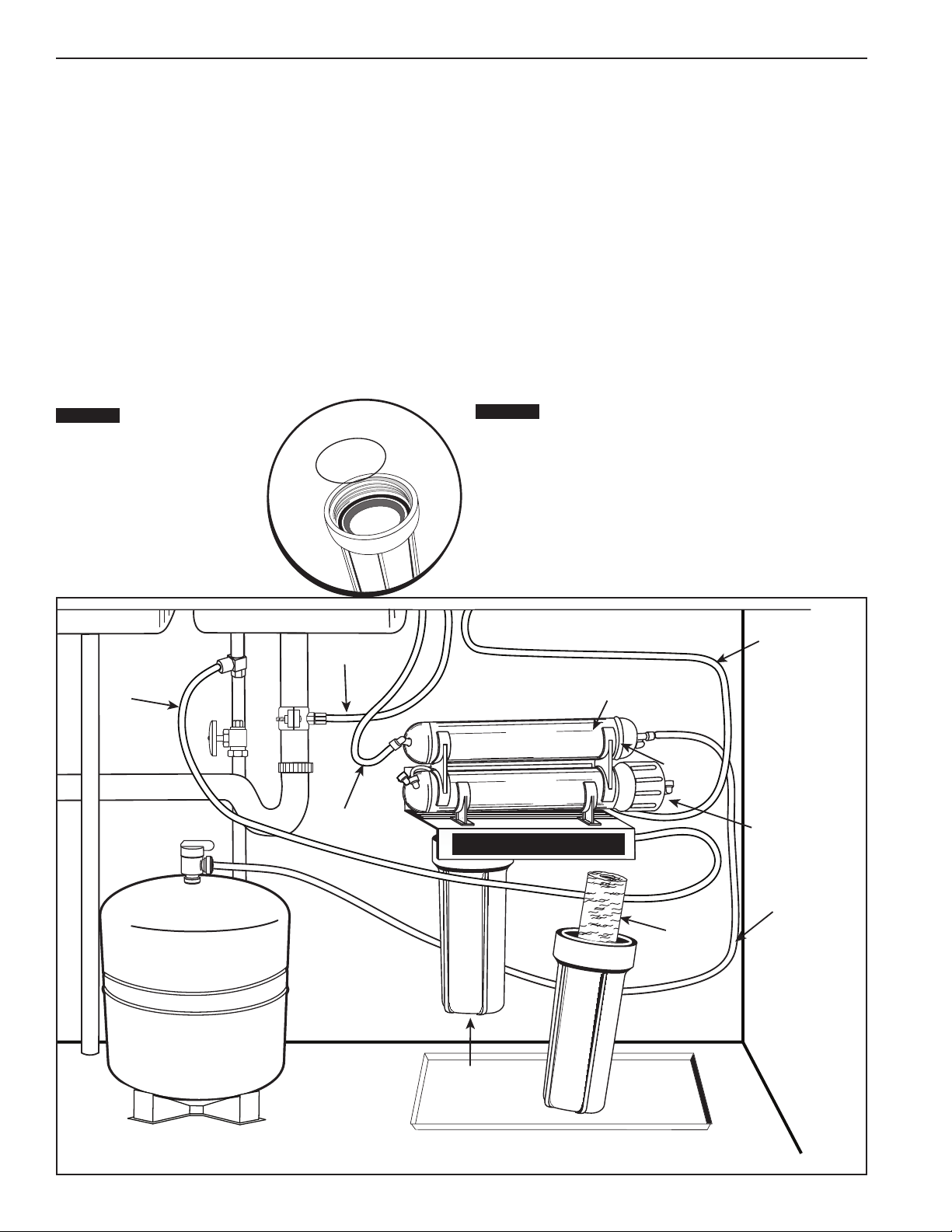
Leaks between bottom of housing and cap
1. Ensure sump is tightly screwed to cap. If it still leaks close the cold
water supply and tank valves.
2. Clean black rubber O-ring and lubricate with clean silicone grease.
With two fingers, insert O-ring in groove below threads of housing
and press into place. Tighten housing back onto cap.
3. Open the cold water supply and tank valve.
If leaks persist, call Technical Support.
Leaks on tank valve assembly
1. Open drinking water faucet to drain storage tank. Let drinking water
faucet run until it drips. Turn off cold water supply.
2. Push in on white collar of tank valve fitting and pull out tubing.
Unscrew the tank valve from the storage tank. Rewrap threads on
top of the tank with Teflon®tape. Screw tank valve back onto tank.
Trim 1/2-inch from end of tubing and reinsert 5/8-inch into tank
valve fitting.
3. Open the cold water supply and shut off the reverse osmosis
faucet. Let the system pressurize for several hours and check for
leaks. Check again after tank is fully pressurized.
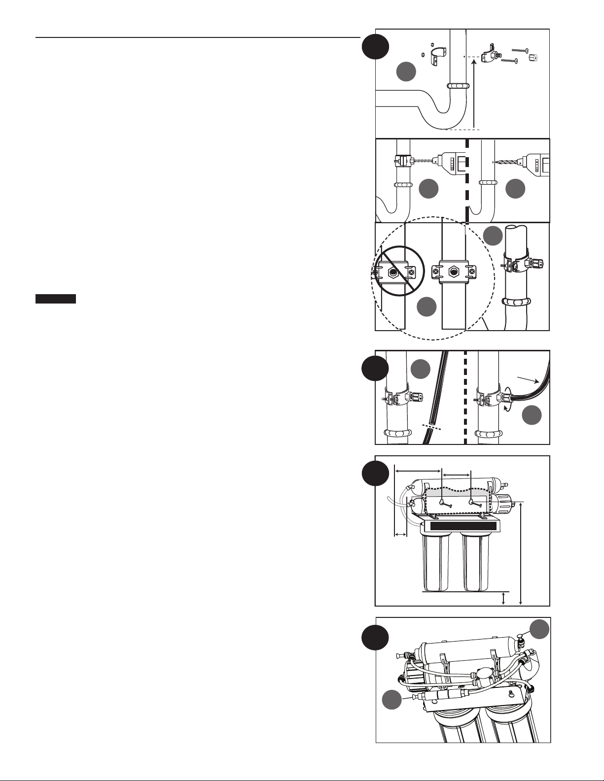
Leaks on quick-connect fittings
1. Close the cold water supply and tank valve.
2. Depress plastic collar and pull out tubing.
3. Cut off 1 inch of tubing and place a mark 5/8-inch from end of
tubing. Tubing should be cut squarely. The internal and external
burrs should be removed.
4. Push tubing 5/8-inch into fitting.
5. Open the cold water supply and tank valve. If leaks persist, call
Technical Support.
No flow or slow flow from the brine (drain) line
Less than 1½ cups per minute
NOTE: Before checking brine (or reject) flow, make sure the system
is producing water by turning off the valve on the storage tank
and opening the faucet. Water should drip from faucet.
1. Examine the P5 and EPM10 pre-filters. If clogged, replace (see
Replacing the Pre-Filter and Post-Filter on page 8) and recheck the
brine (or reject) flow rate.
2. If the pre-filters are not at fault, the brine (or drain) flow controller is
probably clogged. Call Technical Support.
High TDS in Product Water
1. If high TDS (Total Dissolved Solids) is detected in the product water,
the RO Cartridge may need to be replaced or the reject flow control
tubing may be clogged. If this is a new installation, call Technical
Support.
2. Otherwise, draw 1 gallon of water from the unit. After 10 minutes,
then run water from the faucet and test the water again.
3. Determine when you last changed the RO Filter Cartridge and call
Technical Support.
Reduced production
Slow or no product water flow usually indicates either a clogged pre-
filter or an exhausted membrane. First, replace the pre-filters. If the
production rate is not improved, replace membrane.
Gradual return of taste and odor
Gradual return of unpleasant taste and odor over a period of time may
indicate that your filter cartridges and/or RO membrane need to be
replaced.
See Replacing the Pre-Filters on page 8
and Replacing the
Reverse Osmosis Membrane”on page 9.
Sudden return of taste and odor
If shortly after complete servicing noticeable taste and odors return
contact Technical Support.
No water pressure from the drinking water faucet or
low volume in storage tank
1. Close the cold water supply to system.
2. Lift storage tank to see if it is empty. If not, open the drinking water
faucet to empty water from tank.
NOTE: It may be necessary to pump a small amount of air into the tank
with a bicycle pump to remove all the water from the tank.
3. When tank is empty, use a pressure gauge to check tank pressure.
An empty tank should contain 5 to 7 psi pressure. Increase or
decrease the air pressure in the tank accordingly.
4. Open cold water supply. Let system run for
3 hours to fill tank, then check system performance. If performance
has not improved, call Technical Support.
Performance Data
Important Notice: Read this performance data and compare the
capabilities of this system with your actual water treatment needs. It is
recommended that before installing a water treatment system, you have
your water supply tested to determine your actual water treatment needs.
This system has been tested according to NSF/ANSI 58 for the reduction
of the substances listed below. The concentration for the indicated
substances in water entering the system was reduced to a concentration
less than or equal to the permissible limit for water leaving the system, as
specified in NSF/ANSI 58.
NOTE:
Substances reduced are not necessarily in your water. Filter
must be maintained according to manufacturer’s instructions,
including replacement of filter cartridges.
The tested efficiency rating for this system is 7.68%. Efficiency
rating means the percentage of the influent water to the system
that is available to the user as reverse osmosis treated water under
operating conditions that approximate typical daily usage. The tested
recovery rating is 20.1%. Recovery rating means the percentage
of the influent water to the membrane portion of the system that is
available to the user as reverse osmosis treated water when the
system is operated without a storage tank or when the storage tank is
bypassed
Model WRO-2550
Substance
Average Influent
Concentration
Maximum
Permissible
Product Water
Concentration
Reduction
Requirements
Average
Reduction
Standard 58
Barium 10.0 mg/L ± 10% 2.0 mg/L 98.3%
Cadmium 0.03 mg/L ± 10% 0.005 mg/L 98.7%
Chromium
(Hexavalent) 0.3 mg/L ± 10% 0.1 mg/L 91.2%
Chromium
(Trivalent) 0.3 mg/L ± 10% 0.1 mg/L 94.8%
Copper 3.0 mg/L ± 10% 1.3 mg/L 98.9%
Cysts Min. 50,000 /mL 99.95% 99.99%
Fluoride 8.0 mg/L ± 10% 1.5 mg/L 95.6%
Lead 0.15 mg/L ± 10% 0.010 mg/L 98.7%
Radium
226/228 25 pCi/L ± 10% 5 pCi/L 80.0%
Selenium 0.10 mg/L ± 10% 0.05 mg/L 96.0%
Turbidity 11 NTU ± 1 NTU 0.5 NTU 99.0%
Total
Dissolved
Solids
750 mg/L ± 40
mg/L 187 mg/L 96.2%
Troubleshooting Guide
10

1 SH244796 Drain Clamp
2 SH244797 Inlet Supply Adapter
3 SH244820 Faucet
4 SH153049 Housing
5 SH244794 1/4-inch Tubing
6 SH244795 3/8-inch Tubing
7 SH244783 Tank Valve (1/4" NPT x 1/4" QC)
8 SH244833 Storage Tank
9 555021-52 1st Stage Sediment Pre-filter (P5)
2nd Stage Pre-filter (EPM1O)
10 161091 3rd Stage RO Membrane TFM-50
Parts Guide
11 255521-51 4th Stage Post-filter
12 150539 SW-1 Wrench
13 150640 RO Housing Wrench
14 143495 Silicone
15 SH244835 Faucet Adaptor 7/16-24 UNS x 3/8" QC
16 SH244787 Valve Auto Shut-off
17 161075 Membrane Housing
18 SH150646 TDS Test Kit
* SH244837 Flow Restrictor, TFM-50
* Not Shown.
For replacement parts, contact your nearest Water Filter dealer or call 800.279.9404
14
3
2
7
8
5
6
1110
9
12
14
13
15
16
17 18
11

© 2011 Pentair Residential Filtration, LLC SH247244 Rev A FE11
Pentair Water • 5730 North Glen Park Road • Milwaukee, WI 53209 USA
Technical Support: 800.279.9404
www.americanplumber.com
American Plumber®
LIMITED WARRANTY
Reverse Osmosis Systems
American Plumber® warrants to the original owner (under normal use): Reverse Osmosis Systems to be free from defects in material and/or workmanship one
(1) year from the date of purchase. Any replacement products furnished will be free from defects in material and/or workmanship for the remainder of the
original warranty period. This warranty does not cover: (1) pre and post lter cartridges, or reverse osmosis membrane (2) defects not reported within the
above time period, (3) items manufactured by other companies, (4) problems arising from failure to comply with American Plumber® instructions, (5) problems
and/or damage arising from acts of nature, abuse, misuse, negligence or accident by any party other than American Plumber® (6) problems and/or damage
resulting in whole or in part from alteration, modication, repair or attempted alteration, modication or repair by any party other than American Plumber, (7)
noncompliance with applicable codes/ordinances.
If a defect in workmanship and/or material in a product or part covered by the warranty should arise, American Plumber®, at its sole discretion, will repair or
replace the defective product or part (American Plumber® may consider, in good faith, the customer’s preference).
All claimed defective product must: (1) be authorized for return by American Plumber® with an RGA number (2) include proof of the purchase date of
the product or part (3) returned to American Plumber® prior to the expiration of the warranty date, at the customer’s expense, shipment pre-paid, (4) be
accompanied by a letter detailing the Model Number, Serial Number (if any), and a brief description of the problem.
TO THE MAXIMUM EXTENT PERMITTED BY APPLICABLE LAW, AMERICAN PLUMBER® DISCLAIMS ALL OTHER WARRANTIES, WHETHER EXPRESS OR
IMPLIED, INCLUDING, BUT NOT LIMITED TO, THE IMPLIED WARRANTY OF MERCHANTABILITY AND FITNESS FOR A PARTICULAR PURPOSE, WITH REGARD
TO THE PRODUCTS, PARTS AND ANY ACCOMPANYING WRITTEN MATERIALS.
To the maximum extent permitted by applicable law, American Plumber® shall not be liable for any damages whatsoever (including, but not limited to, loss of
time, inconvenience, expenses, labor or material charges incurred in connection with the removal or replacement of the Filtration System, special, incidental,
consequential, or indirect damages for personal injury, loss of business prots, business interruption, loss of business information, or any other pecuniary loss)
arising out of the use of or inability to use the defective products or parts, even if American Plumber® has been advised of the possibility of such damages.
American Plumber® maximum liability under any provision of this Limited Warranty shall be limited to the amount actually paid for the product or part.
NOTE: Because some states do not allow the exclusion or limitation of incidental or consequential damages, the above limitations or exclusions may not apply.
THIS WARRANTY GRANTS SPECIFIC LEGAL RIGHTS, AND OTHER RIGHTS MAY APPLY. SUCH RIGHTS VARY FROM STATE TO STATE.
IOWA RESIDENTS ONLY:
Store or seller’s name
Address
City State Zip
Seller’s signature
Customer’s signature Date
Table of contents
Other American Plumber Water Filtration System manuals
Popular Water Filtration System manuals by other brands

SunSun
SunSun HW-702A Operation manual

Thermal Care
Thermal Care SF Series Operation, installation, and maintenance manual

Keating Of Chicago
Keating Of Chicago Safe and Easy Filter owner's guide

AMI
AMI AAA-RO50UVA MANUAL FOR INSTALLATION, OPERATION AND MAINTENANCE

Clear2O
Clear2O GRP200 use and care manual

Monzana
Monzana MZPP14 manual